



















Diamond Band Saw Blades: Engineering Selection, Cutting Performance, and Cost per Part

Table of Contents
Toggle
American Based Manufacturer

Established in 1990


Custom manufacturing


Diamond band saw blades can produce excessive edge chipping, dimensional deviation, wide kerf, and premature abrasive wear when blade construction does not match the material, workpiece geometry, or machine conditions. Replacing the blade without identifying the limiting variable may increase tooling expense without improving accepted production output.
For engineers cutting quartz, glass, silicon, technical ceramics, graphite, or abrasive composites, blade selection involves more than diamond grit size. Abrasive retention, backing stiffness, cutting height, edge configuration, guide alignment, tension, feed, and coolant delivery determine whether the process remains stable throughout blade life.
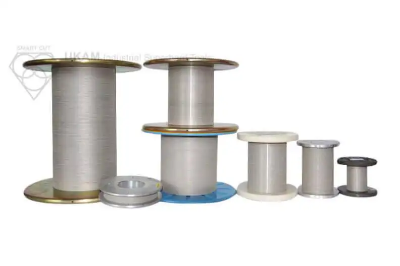
Unlike circular blades, continuous diamond bands can cut curved profiles, irregular shapes, and tall sections. Their economic value must be demonstrated through dimensional accuracy, acceptable surface integrity, repeatable cutting time, and total cost per accepted component.
When Should Engineers Reconsider Diamond Band Saw Blades?
A blade specification review is justified when production cannot consistently meet dimensional, surface quality, throughput, or tool life requirements.
The first investigation should distinguish abrasive limitations from machine and workholding problems.
|
Production symptom |
Potential contributing variables |
Required verification |
|---|---|---|
|
Coarse grit, excessive feed, unsupported exit edge |
Measure chip size and location |
|
|
Guide wear, insufficient tension, excessive lateral loading |
Measure profile deviation and inspect tracking |
|
|
Abrasive wear, loading, restricted debris removal |
Record cycle time throughout blade life |
|
|
Excessive kerf |
Backing gauge, abrasive projection, lateral movement |
Measure actual kerf at multiple locations |
|
Premature band fracture |
Wheel bending stress, weld condition, tracking |
Inspect backing and fracture location |
|
Material variation, installation, operating conditions |
Compare accepted output across multiple blades |
Engineering Insight: Failure Timing Helps Identify Root Cause
Immediate wandering after installation suggests a different investigation from deviation that develops after prolonged cutting.
For immediate deviation, inspect guides, tension, tracking, workholding, and blade geometry. For progressive deviation, evaluate abrasive wear, increasing cutting resistance, and guide condition.
A supplier change should follow a documented diagnosis, not replace it.
Establish a Measurable Production Baseline
A controlled comparison requires an accurate record of the existing cutting process.
Without baseline measurements, differences in material batches, feed settings, operator technique, or machine condition may be mistaken for blade improvements.
|
Parameter |
Required baseline information |
|---|---|
|
Material |
Exact grade, hardness, density, batch, relevant microstructure |
|
Workpiece |
Height, thickness, geometry, minimum contour radius |
|
Machine |
Saw model, wheel diameter, guide arrangement |
|
Blade |
Length, width, gauge, grit, abrasive construction, edge configuration |
|
Setup |
Tension, tracking, guide clearance, workholding |
|
Band speed, feed, coolant delivery |
|
|
Dimensional quality |
Kerf, straightness, contour deviation |
|
Chipping, cracking, grain pullout, delamination |
|
|
Productivity |
Cutting time, accepted output, rejected output |
|
Tool life |
Total cuts, accepted cuts, removal criterion |
|
Economics |
Blade cost, machine rate, changeover, scrap |
Engineering Insight: Band Gauge Is Not Cutting Kerf
The steel backing is narrower than the abrasive-coated cutting envelope.
For a symmetrically coated band:
Nominal coated width = Backing gauge + 2 × Abrasive projection
Where abrasive projection is measured outward from each side of the backing.
For example, a 0.025-inch backing with 0.015-inch projection on each side produces a nominal coated width of 0.055 inch.
Actual cutting kerf may differ because of abrasive distribution, blade deflection, and cutting conditions. Measure the cut rather than relying on nominal geometry alone.
For expensive crystals and technical ceramics, kerf reduction must be evaluated alongside part yield and dimensional acceptance.
Compare Cost per Accepted Part, Not Blade Purchase Price
Blade purchase price alone does not establish manufacturing economy.
A higher-priced blade may reduce cost through shorter cutting time, lower scrap, or longer useful life. A longer-lasting blade may still be uneconomical if its cutting rate deteriorates substantially.
Illustrative Cost-per-Accepted-Part Comparison
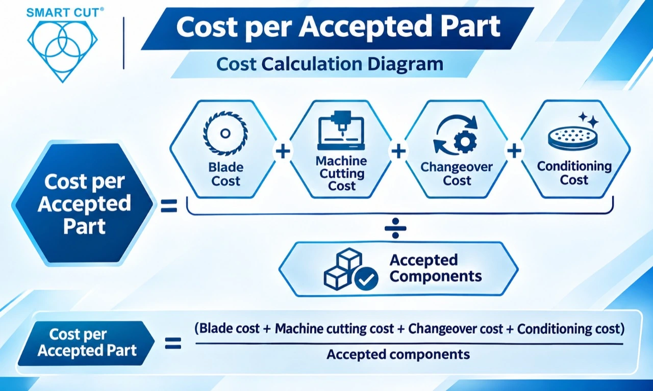
The following values are entirely hypothetical and are used only to demonstrate the calculation method. They are not actual UKAM test results, supplier quotations, or verified comparative performance data.
|
Production variable |
Hypothetical Blade A |
Hypothetical Blade B |
|---|---|---|
|
Blade price |
$180 |
$290 |
|
Total attempted cuts |
300 |
650 |
|
Conditioning frequency |
None |
None |
|
Cutting time per attempted cut |
4.5 minutes |
3.5 minutes |
|
Scrap rate |
5% |
2% |
|
Machine operating rate |
$75/hour |
$75/hour |
|
Blade changeover |
20 minutes |
20 minutes |
|
Accepted components |
285 |
637 |
|
Blade cost per accepted part |
$0.63 |
$0.46 |
|
Machine cost per accepted part |
$5.92 |
$4.46 |
|
Changeover cost per accepted part |
$0.09 |
$0.04 |
|
Total cost per accepted part |
$6.64 |
$4.96 |
Cost per accepted part = (Blade cost + Machine cutting cost + Changeover cost + Conditioning cost) ÷ Accepted components
Machine cutting cost includes time spent on rejected components.
Under these illustrative assumptions, Blade B reduces calculated cost by approximately $1.68 per accepted component despite its higher initial purchase price.
The example excludes material value, downstream finishing, and inspection. Include these costs whenever they differ between candidate processes.
No comparative performance claim is made about UKAM or another manufacturer.
Engineering Insight: Define Useful Life by Production Acceptance
Blade life should end when the process exceeds an approved limit for chipping, dimensional deviation, kerf, cutting time, or mechanical condition.
Total cuts alone can conceal increasing scrap or declining productivity. Track acceptable output throughout the blade’s service life.
Select Abrasive Construction, Grit, and Edge Geometry
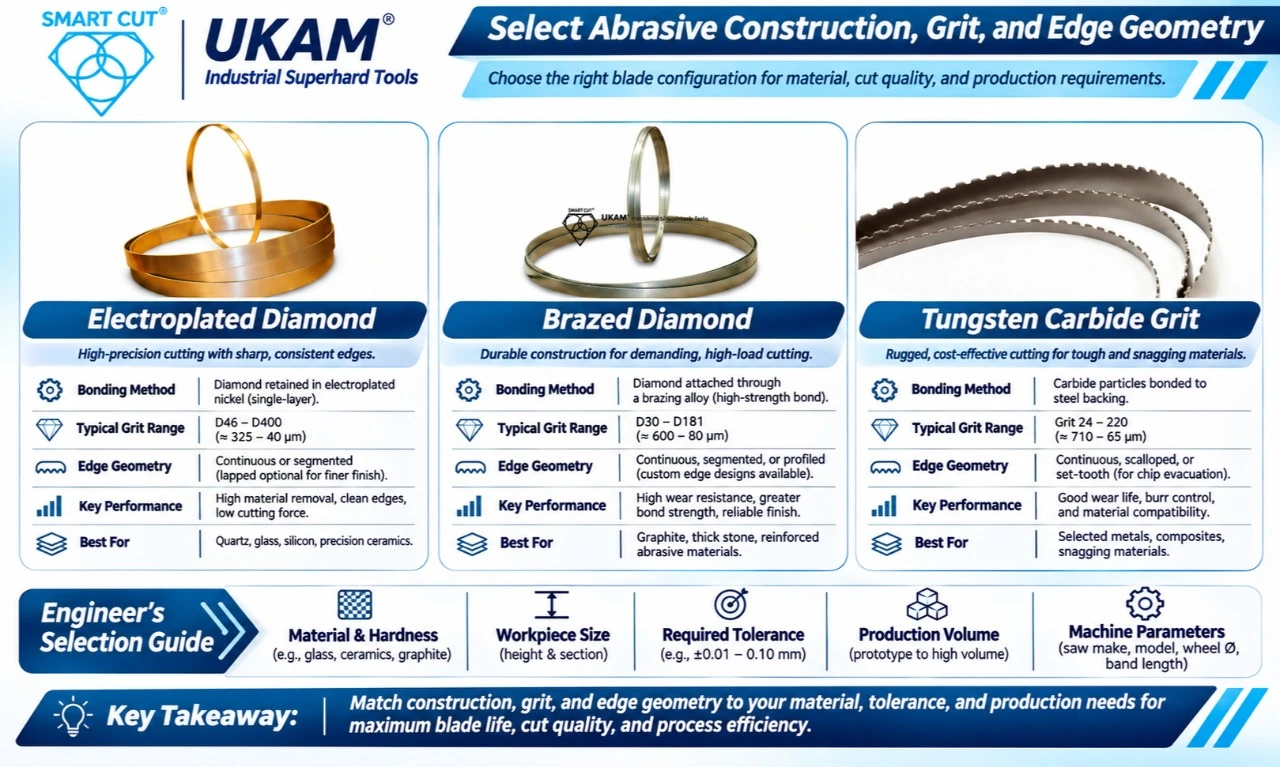
Different blade constructions provide different abrasive retention and cutting characteristics.
|
Construction |
Technical characteristics |
Applications to evaluate |
Principal concern |
|---|---|---|---|
|
Diamond retained in electroplated nickel |
Quartz, glass, silicon, precision ceramics |
Abrasive wear, loading, edge quality |
|
|
Diamond attached through brazing alloy |
Graphite, thick stone, reinforced abrasive materials |
Cutting load, wear, finish |
|
|
Carbide particles bonded to steel |
Selected metals, composites, snagging materials |
Burrs, wear, compatibility |
Tungsten carbide grit bands are a companion technology, not a diamond bond.
Diamond Grit Selection
UKAM’s general selection guidance identifies the following categories:
|
Grit category |
Mesh guidance |
Selection consideration |
|---|---|---|
|
Coarse |
25/30 to 50 |
Thick sections, aggressive cutting, debris clearance |
|
Medium coarse |
40 to 70 |
Dense ceramics and selected composites |
|
Medium |
70 to 100 |
General abrasive sectioning |
|
Fine |
100 to 140 |
Quartz, glass, finish-sensitive ceramics |
|
Very fine |
140 to 200 |
Selected optical and detailed applications |
These are general selection categories, not confirmed availability for every blade construction.
Coarser abrasive may improve cutting engagement but increase local brittle fracture. Finer abrasive may reduce some edge damage while increasing rubbing or loading.
Final selection requires representative cutting trials.
Edge Configuration
|
Edge style |
Engineering consideration |
|---|---|
|
Continuous |
Consistent abrasive engagement for finish-sensitive cutting |
|
Segmented |
Additional clearance paths for coolant and debris |
|
Gulleted |
Increased space for debris evacuation |
|
Scalloped |
Alternative engagement and clearance geometry |
|
Dotted |
Distributed abrasive contact for selected applications |
Edge availability depends on blade construction. A segmented edge should not be selected solely for faster cutting if the finished part cannot tolerate its surface characteristics.
Specify Band Width, Gauge, Kerf, and Contour Geometry
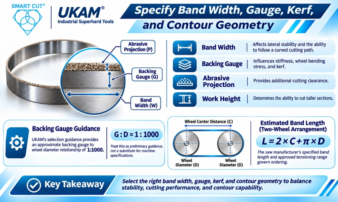
Band width affects lateral stability and the ability to follow a curved cutting path.
Wider bands generally provide better support for straight cuts. Narrower bands can negotiate tighter curves but may be more sensitive to lateral loading.
Backing gauge influences stiffness, wheel bending stress, and kerf.
|
Geometry variable |
Potential benefit |
Engineering tradeoff |
|---|---|---|
|
Greater band width |
Improved straight-cut stability |
Larger minimum achievable contour radius |
|
Greater backing gauge |
Increased resistance to deflection |
Higher bending demand and kerf |
|
Greater abrasive projection |
Additional cutting clearance |
Increased nominal coated width |
|
Greater work height |
Ability to cut taller sections |
Longer engagement and potential deviation |
UKAM’s selection guidance provides an approximate backing gauge to wheel diameter relationship of 1:1000. Treat this as preliminary guidance, not a substitute for machine specifications.
For a simple two-wheel arrangement with equal wheel diameters:
Estimated band length = 2 × Wheel center distance + π × Wheel diameter
The saw manufacturer’s specified band length and approved tensioning range govern ordering.
Engineering Insight: Minimum Contour Radius Requires Verification
A narrow band can follow a smaller radius, but the achievable contour also depends on coated kerf, blade width, backing flexibility, guide support, and feed.
Do not calculate a guaranteed minimum contour radius from band width alone. Confirm the required radius with the supplier and a representative cutting trial.
Use Material-Specific Operating Guidance
UKAM’s technical brochure provides starting specifications for selected electroplated blade applications.
|
Material |
Work height |
Example band width × gauge |
Published band speed |
Edge |
|---|---|---|---|---|
|
1–6 in |
1 × 0.020 in |
2,000–2,500 SFPM |
Continuous or segmented |
|
|
1–6 in |
1 × 0.020 in |
1,800–2,200 SFPM |
Continuous |
|
|
Ceramic |
1–6 in |
1 × 0.020 in |
1,800–2,200 SFPM |
Continuous |
|
Carbide |
1–4 in |
3/4 × 0.020 in |
1,800–2,200 SFPM |
Continuous |
These are published starting references, not universal operating limits or guarantees of product availability.
Confirm material grade, coolant requirements, work height, wheel compatibility, and approved blade construction before applying them.
Fused Silica and Quartz
Primary failure: Edge chipping and subsurface microcracking.
Fused silica is amorphous, while crystalline quartz has orientation-dependent properties.
Measure entrance and exit chipping separately. If damage increases near breakthrough, investigate workpiece support, feed, and cutting engagement.
A continuous edge may be evaluated when edge integrity is the primary acceptance criterion.
Alumina
Primary failure: Grain pullout and brittle edge fracture.
Alumina cutting behavior varies with purity, porosity, density, and grain size.
Inspect the cut surface for grain loss and record maximum chip size. Compare results across material batches before attributing variation to abrasive wear.
Evaluate grit, feed stability, and coolant delivery together with cutting time.
Silicon Carbide
Primary failure: Progressive abrasive wear and localized edge microfracture.
Sintered and reaction-bonded silicon carbide can behave differently because of their microstructures.
Record cutting time, kerf, edge damage, and abrasive condition at defined intervals.
If cutting time increases while edge quality remains acceptable, investigate abrasive wear or loading. If chipping increases without a corresponding cutting-time change, inspect support, engagement, and feed stability.
Silicon Nitride
Primary failure: Localized fracture and possible subsurface damage.
Silicon nitride behavior depends on material grade and processing history.
Inspect representative edges and surfaces using methods appropriate to the component requirements. A visually smooth cut does not establish the absence of subsurface damage.
Evaluate support, feed, and cutting engagement before approving a specification.
Sapphire
Primary failure: Orientation-dependent chipping and cracking.
Sapphire is a single-crystal material. Record crystallographic orientation and cutting direction during qualification.
Compare edge integrity and dimensional results under consistent conditions. Approval for one orientation should not automatically extend to another.
Tungsten Carbide
Primary failure: Edge chipping and accelerated abrasive wear.
Cemented tungsten carbide contains hard carbide grains and a metallic binder.
Record the exact grade and binder content. Monitor kerf, cutting rate, and abrasive condition.
If efficiency declines, inspect abrasive wear and loading before increasing feed.
Graphite and Carbon Materials
Primary failure: Edge breakout, surface crumbling, and debris accumulation.
Graphite grades differ in density, porosity, and grain structure.
Inspect unsupported edges and the cutting zone. For approved dry cutting, use suitable dust extraction and machine protection.
Compare electroplated and brazed constructions through controlled trials rather than assuming one will always produce longer life.
Fiber-Reinforced Composites
Primary failure: Delamination, fiber pullout, and matrix damage.
Carbon fiber and fiberglass composites combine abrasive reinforcement with a polymer matrix.
Inspect cut edges for exposed fibers and layer separation. Evaluate feed, workholding, abrasive configuration, and debris removal across representative fiber orientations.
Qualify a Blade Through Eight Controlled Phases
A new blade should be approved using a repeatable production qualification process.
|
Phase |
Required activity |
Evidence |
|---|---|---|
|
Define requirements |
Establish dimensional and surface limits |
Approved acceptance criteria |
|
Inspect guides, wheels, tracking, tension |
Machine condition record |
|
|
Measure baseline |
Document current blade performance |
Reference data |
|
Select candidates |
Compare bond, grit, width, gauge, edge |
Selection rationale |
|
Change controlled variables |
Trial records |
|
|
Inspect components |
Measure kerf, profile, chipping |
Inspection results |
|
Evaluate useful life |
Track accepted output and cycle time |
Cost per accepted part |
|
Test additional blades and material batches |
Production approval |
Example: Investigating Edge Chipping in Silicon Carbide
Consider a silicon carbide cutting process with increasing edge defects. This is a proposed diagnostic procedure, not a report of completed testing.
First, document the material grade, blade specification, band speed, feed, coolant, and workholding.
Next, measure maximum chip size at entrance, middle, and exit locations. Inspect the blade for uneven wear and verify guide condition.
Run a controlled comparison with one approved variable changed, such as grit or feed. Maintain the same inspection method and material grade.
Repeat the trial over a representative portion of blade life.
Approve the candidate only if it meets predetermined edge, dimensional, productivity, and economic acceptance criteria.
Engineering Insight: One Successful Cut Is Not Production Qualification
Initial sharpness can conceal later loading, uneven abrasive wear, or declining cutting efficiency.
Qualification should include multiple blades and representative material batches where production risk justifies the testing.
Evaluate Suppliers Against Production Requirements
|
Supplier evaluation question |
What the answer establishes |
|---|---|
|
Which abrasive construction is proposed? |
Material compatibility and cutting mechanism |
|
What grit and edge configurations are available? |
Ability to address finish and debris removal |
|
Which dimensional tolerances are controlled? |
Replacement consistency |
|
How are welds manufactured and inspected? |
Joint quality control |
|
What operating limits apply? |
Machine compatibility |
|
Which maintenance procedures are approved? |
Appropriate conditioning and cleaning |
|
Technical qualification capability |
|
|
Production supply continuity |
The approved purchase specification should identify band length, width, gauge, abrasive construction, grit, edge configuration, backing, and revision information.
SMART CUT® Diamond Band Saw Blade Technology Comparison
UKAM Industrial Superhard Tools offers SMART CUT® electroplated diamond, brazed diamond, and tungsten carbide grit band technologies.
|
Specification |
Electroplated diamond |
Brazed diamond |
Tungsten carbide grit |
|---|---|---|---|
|
Abrasive |
Diamond |
Diamond |
Tungsten carbide |
|
Attachment |
Nickel electroplating |
Brazing alloy |
Bonded grit |
|
Application focus |
Quartz, glass, silicon, ceramics |
Graphite, stone, reinforced abrasive materials |
Selected metals and composites |
|
Edge options |
Continuous, segmented, gulleted, scalloped, dotted |
Construction-dependent continuous, segmented, gulleted |
Confirm by specification |
|
Backing |
Stainless or carbon steel |
Alloy steel |
Steel |
|
Main qualification criteria |
Kerf, chipping, abrasive wear |
Cutting load, finish, wear |
Burrs, wear, material compatibility |
UKAM documents custom cut-and-welded band lengths and application-specific selection of width, gauge, grit, and edge style.
Published specifications may vary across UKAM product materials. Confirm exact configuration and availability before ordering.
Production Qualification Checklist
Material and component
- Exact material grade and batch recorded.
- Workpiece geometry and minimum radius documented.
- Dimensional and surface acceptance limits approved.
Machine and blade
- Band length, width, and gauge verified.
- Wheel diameter, guides, and tracking inspected.
- Tension and operating limits confirmed.
- Weld and backing inspected.
Cutting process
- Band speed and feed documented.
- Coolant or approved dry-cutting controls verified.
- Workholding and debris management checked.
Performance and purchasing
- Representative components inspected.
- Accepted output and scrap recorded.
- Useful blade life established.
- Cost per accepted part calculated.
- Repeatability and final specification approved.
Frequently Asked Questions
Electroplated blades retain diamond particles in nickel, while brazed blades use a metallurgical attachment. Electroplated constructions are commonly evaluated for precision cutting of quartz, glass, silicon, and ceramics. Brazed constructions may be considered for graphite, thick stone, and reinforced abrasive materials. Compare measured cutting quality, kerf, cutting rate, and useful life before selecting a construction.
Select grit according to material behavior, work height, required surface integrity, and cutting productivity. Coarser grit may improve clearance and cutting engagement but increase local brittle fracture. Finer grit may reduce some edge damage while increasing rubbing or loading. Confirm performance through controlled trials.
Possible causes include insufficient tension, worn guides, incorrect tracking, excessive feed, inadequate stiffness, and uneven abrasive wear. Inspect the machine first. If the setup is acceptable, evaluate band geometry and cutting load using measured profile deviation.
There is no universal number of cuts or operating hours. Useful life depends on material, blade construction, cutting conditions, and acceptance criteria. Record accepted components until dimensional quality, edge integrity, productivity, or blade condition reaches the approved replacement limit.
Suitable diamond bands can be evaluated for these materials, subject to grade-specific qualification. Silicon carbide can impose substantial abrasive wear, while alumina may exhibit grain pullout and brittle fracture. Compare cutting rate, edge condition, kerf, and blade life using representative workpieces.
Some constructions and applications permit dry cutting, while others require coolant. Confirm compatibility with the specific blade and machine. Dry cutting graphite, ceramics, and composites may require appropriate dust extraction and containment.
No. A thinner band may reduce nominal kerf loss but can also reduce stiffness and increase sensitivity to deflection. If cutting time or scrap increases, the material saving may not justify the change. Evaluate accepted output and total cost per part.
Provide the saw manufacturer and model, wheel diameter, band length, material grade, workpiece height, minimum contour radius, current blade specification, cutting conditions, quality requirements, quantity, and delivery date. Include a drawing or photograph when available.
Engineering Summary
- Select diamond band saw blades according to material behavior, cutting geometry, and finished part requirements.
- Verify machine condition before attributing cutting problems to abrasive construction.
- Match bond, grit, edge style, band width, and backing gauge to measurable production limitations.
- Record kerf, chipping, dimensional deviation, cycle time, and accepted output.
- Evaluate suppliers using cost per accepted component and specification consistency.
- Confirm performance over useful blade life before production approval.
Request a Diamond Band Saw Blade Engineering Review
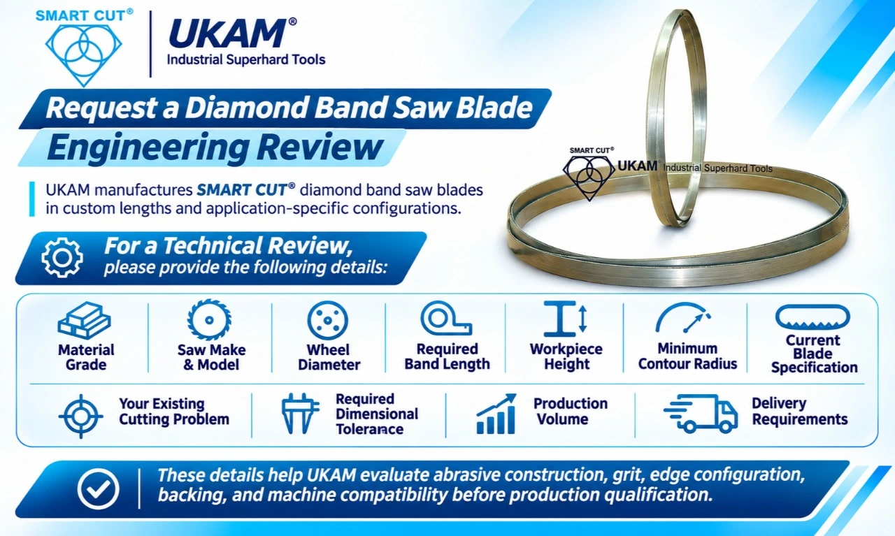
UKAM Industrial Superhard Tools manufactures SMART CUT® diamond band saw blades in custom lengths and application-specific configurations.
For a technical review, provide your material grade, saw make and model, wheel diameter, required band length, workpiece height, minimum contour radius, and current blade specification.
Include your existing cutting problem, required dimensional tolerance, production volume, and delivery requirements.
These details help UKAM evaluate abrasive construction, grit, edge configuration, backing, and machine compatibility before production qualification.
Trusted by Tens of Thousands of Manufacturers, Laboratories,
Research Institutions Worldwide Since 1990
American Based Manufacturer
Established in 1990
