








































Troubleshooting Common Diamond Blade Wear Patterns


Table of Contents
Toggle
American Based Manufacturer

Established in 1990


Custom manufacturing


How to identify blade wear, distinguish the failure mechanism, and qualify the next process change
A diamond blade rarely fails in only one way.
The working edge may glaze, load with work material, lose abrasive exposure, wear unevenly, develop a rounded profile, show localized wear, or continue cutting while producing increasingly poor parts. Each condition points toward a different investigation.
Replacing the blade immediately can restore production, but it does not necessarily identify why the previous blade failed.
For engineers and manufacturers, the more useful question is:
What does the wear pattern tell us about the interaction between the blade, material, machine, coolant, and cutting conditions?
The answer requires more than visual inspection. Blade condition should be compared with cutting rate, edge quality, kerf, dimensional results, heat generation, runout, dressing response, accepted parts, and tool life.
A blade that physically survives for a long time is not necessarily providing useful production life if the sections are already outside specification.
This article provides a structured method for investigating common diamond blade wear patterns and deciding what should be checked before changing the blade specification.
Identify the Wear Pattern Before Changing the Blade
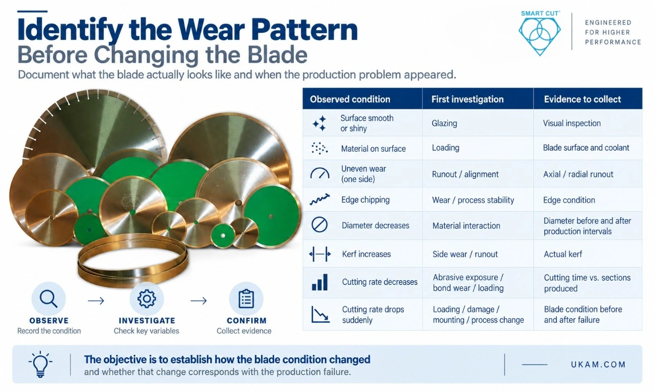
Start by documenting what the blade actually looks like and when the production problem appeared.
The timing of the failure is often as useful as the appearance of the worn blade.
|
Observed condition |
First investigation |
Evidence to collect |
|---|---|---|
|
Cutting rate gradually decreases |
Abrasive exposure, bond wear, loading |
Cutting time versus sections produced |
|
Cutting rate drops suddenly |
Loading, damage, mounting, process change |
Blade condition before and after failure |
|
Blade surface appears smooth or shiny |
Glazing or loss of effective abrasive exposure |
Microscopic or visual surface inspection |
|
Work material covers abrasive surface |
Loading |
Blade surface condition, material type, coolant |
|
Wear is concentrated on one side |
Runout, alignment, mounting, deflection |
Radial and axial runout |
|
Blade diameter decreases rapidly |
Material interaction, bond wear, process load |
Diameter before and after defined production intervals |
|
Kerf increases during production |
Side wear, runout, blade deflection |
Actual kerf and mounted blade condition |
|
Edge chipping increases with blade age |
Wear, geometry change, process stability |
Edge condition versus blade life |
|
Wear occurs only in one section of the blade |
Mounting, material engagement, blade geometry |
Circumferential wear pattern |
|
Blade still cuts but parts fail inspection |
Dimensional or surface degradation |
Part measurements versus blade condition |
The first objective is not to decide that the blade is defective.
The objective is to establish how the blade condition changed and whether that change corresponds with the production failure.
Establish the Original Blade and Process Baseline
A wear pattern has little meaning without a baseline.
Record the blade specification and the actual process before evaluating a replacement.
|
Parameter |
Record |
|---|---|
|
Work material |
Exact grade and production condition |
|
Workpiece thickness |
Actual thickness |
|
Required section |
Thickness, geometry, dimensional tolerance |
|
Edge requirement |
Maximum permitted chip or breakout |
|
Surface requirement |
Ra or other defined inspection criterion |
|
Blade diameter |
New and current diameter |
|
Blade thickness |
Nominal and measured where relevant |
|
Kerf |
Actual production kerf |
|
Stated concentration |
|
|
Bond |
Metal, resin, nickel, brazed or other construction |
|
Arbor |
Actual mounting configuration |
|
Machine |
Manufacturer and model |
|
Actual operating RPM |
|
|
Feed |
Actual feed rate |
|
Coolant |
Type, delivery method and flow |
|
Workholding |
Fixture and support condition |
|
Runout |
Measured at relevant locations |
|
Cutting time |
Actual cycle time |
|
Accepted sections before replacement |
|
|
Scrap |
Rejected section percentage |
Programmed RPM is not necessarily actual RPM.
Nominal blade thickness is not necessarily actual production kerf.
A shank or arbor measurement does not establish the runout at the cutting edge.
These distinctions matter because the blade wear pattern may be a result of the process acting on the blade rather than a standalone blade specification problem.
Recognize Glazing or Loss of Effective Abrasive Exposure
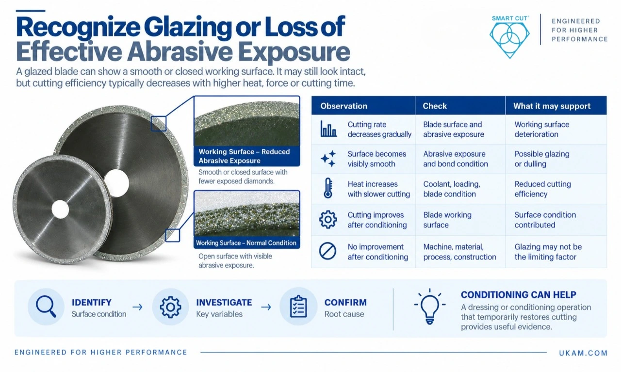
A glazed diamond blade can show a relatively smooth or closed working surface.
The practical symptom is often a reduction in cutting efficiency accompanied by increased heat, force, or cutting time.
The blade may still appear physically intact.
|
Observation |
Check |
What the result may support |
|---|---|---|
|
Cutting rate decreases gradually |
Blade surface and abrasive exposure |
Working surface deterioration |
|
Surface becomes visibly smooth |
Abrasive exposure and bond condition |
Possible glazing or dulling |
|
Heat increases with slower cutting |
Coolant, loading, blade condition |
Reduced cutting efficiency |
|
Cutting improves after appropriate conditioning |
Blade working surface |
Surface condition contributed |
|
No improvement after conditioning |
Machine, material, process, construction |
Glazing may not be the limiting factor |
A dressing or conditioning operation that temporarily restores cutting provides useful evidence about the working surface.
It does not automatically prove why the blade became glazed.
Possible contributors include bond behavior, abrasive specification, material interaction, insufficient coolant, excessive contact load, and process conditions.
For a dressable construction, record the conditioning method, tool, depth, speed, feed, coolant condition, and resulting cutting behavior.
A single layer electroplated diamond blade should not be treated like a conventional dressable bonded blade. Its abrasive layer and construction determine what conditioning methods are appropriate.
Investigate Diamond Blade Loading
Loading occurs when work material accumulates on the abrasive working surface.
The result can be reduced cutting efficiency even though the diamond abrasive itself has not necessarily been consumed.
Loading should therefore be investigated as a working surface condition rather than simply described as excessive wear.
|
Loading pattern |
First checks |
Evidence to collect |
|---|---|---|
|
Loading appears from the beginning |
Material and blade compatibility |
Material condition and blade construction |
|
Loading increases as blade heats |
Coolant and process load |
Coolant delivery and temperature |
|
Loading appears after several sections |
Blade wear and exposure |
Blade condition versus section count |
|
Loading is concentrated in one area |
Alignment and engagement |
Circumferential wear pattern |
|
Conditioning temporarily restores cutting |
Working surface condition |
Cutting rate before and after conditioning |
|
Loading occurs only with one material |
Material interaction |
Controlled material comparison |
Increasing pressure against a loaded blade can increase mechanical and thermal load without resolving the underlying chip clearance problem.
Before increasing feed or changing to a more aggressive blade, establish whether the abrasive is actually cutting or whether work material is interfering with the working surface.
Separate Normal Wear From Accelerated Wear
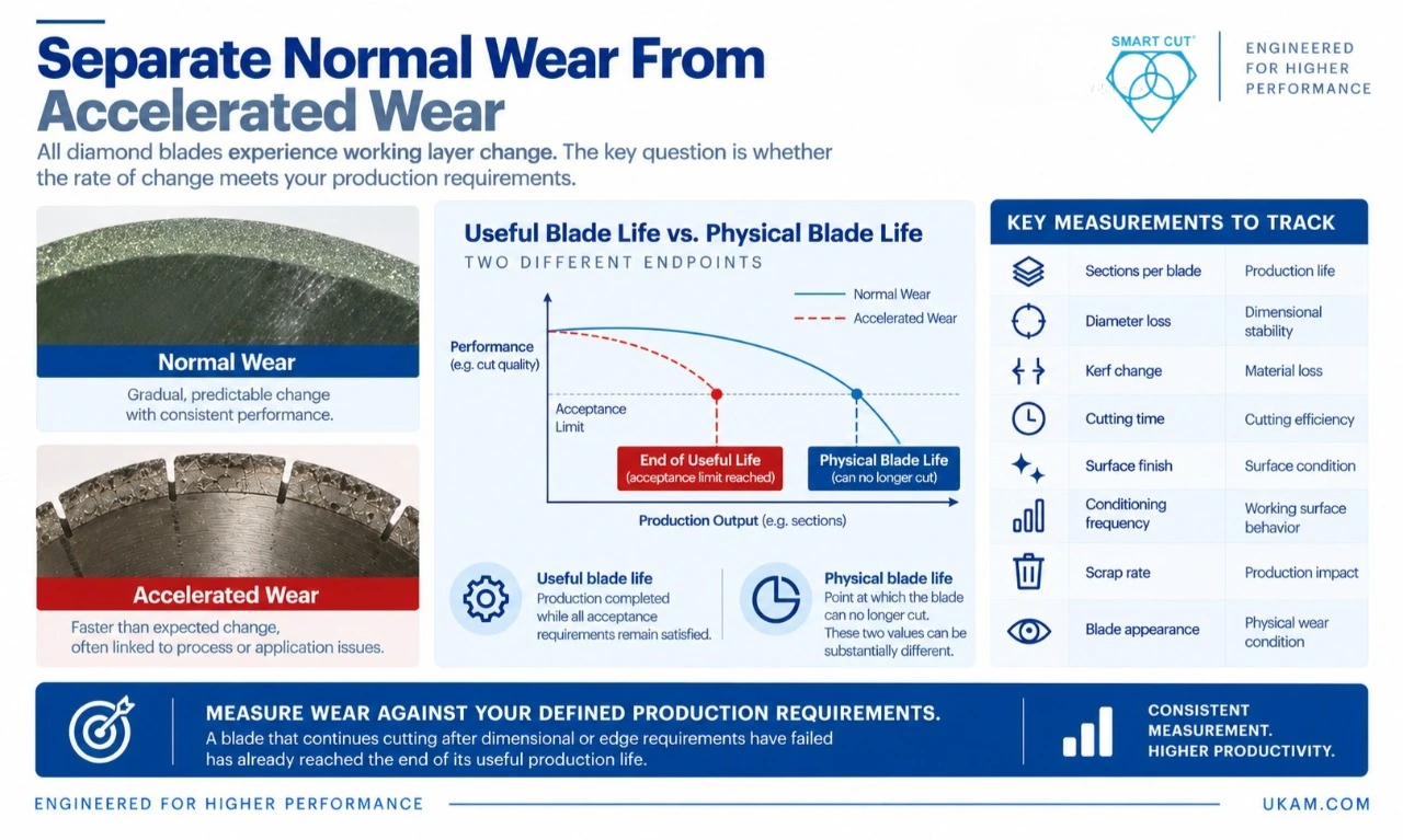
All diamond blades experience some form of working layer change.
The engineering question is whether the rate of change is compatible with the required production output.
Measure wear against a defined production endpoint.
That endpoint may be:
- Loss of dimensional control
- Excessive kerf
- Unacceptable edge damage
- Increasing cutting time
- Excessive heat
- Poor surface quality
- Excessive conditioning frequency
- Increased scrap
A useful blade life measurement therefore looks like this:
Useful blade life = production completed while all defined acceptance requirements remain satisfied
This is different from:
Physical blade life = point at which the blade can no longer cut
The two values can be substantially different.
|
Measurement |
What it tells you |
|---|---|
|
Sections per blade |
Basic production life |
|
Diameter loss |
Dimensional stability |
|
Kerf change |
Material loss and side wear |
|
Cutting time |
Cutting efficiency |
|
Edge damage |
Quality stability |
|
Surface condition |
|
|
Conditioning frequency |
Working surface behavior |
|
Scrap rate |
Production impact |
|
Spindle load |
Process load trend |
|
Blade appearance |
Physical wear condition |
A blade that continues cutting after dimensional or edge requirements have failed has already reached the end of its useful production life.
Check for Uneven or One Sided Wear
Uneven wear is one of the most useful patterns to investigate because the blade may not be experiencing the same engagement around its circumference or across its thickness.
Potential contributors include:
- Radial runout
- Axial runout
- Flange condition
- Arbor seating
- Spindle alignment
- Blade geometry
- Workpiece alignment
- Workholding movement
- Machine deflection
- Blade deflection
|
Wear pattern |
Evidence to collect |
Investigation supported |
|---|---|---|
|
One side wears faster |
Axial runout and flange condition |
Uneven lateral engagement |
|
One circumferential area wears more |
Radial runout and mounting |
Periodic engagement variation |
|
Wear changes after remounting |
Mounted runout before and after remounting |
Mounting contribution |
|
Wear increases with deeper cutting |
Blade stiffness and projection |
Deflection |
|
Wear follows workpiece position |
Workholding and alignment |
Workpiece movement |
|
Same blade wears differently on machines |
Machine and mounting measurements |
Machine interaction |
Do not assign the entire wear pattern to the blade until the complete mounted assembly has been checked.
Investigate Rounded or Worn Cutting Edges
A diamond blade can lose its intended working geometry as abrasive and bond material are removed.
For precision sectioning, the change may appear first as:
- Increasing kerf
- Variable section thickness
- Increased cutting force
- Edge damage
- Longer cutting time
- Blade deflection
- Increased heat
The important measurement is not simply how much material the blade has lost.
Measure whether the working geometry remains capable of producing the required part.
|
Production observation |
Measurement |
|---|---|
|
Section thickness changes |
Section thickness at multiple locations |
|
Kerf increases |
Actual kerf |
|
Cutting time increases |
Cycle time versus blade life |
|
Edge damage increases |
Edge inspection versus blade life |
|
Blade deflects |
Blade movement or cut deviation |
|
Heat increases |
Process temperature indicators and coolant condition |
A blade can remain visually acceptable while its working geometry has changed enough to affect production.
Check for Circumferential Wear Patterns
Wear that repeats around the blade circumference deserves a different investigation from uniform wear.
A repeating pattern can indicate periodic engagement, runout, mounting condition, machine dynamics, or blade geometry.
Measure the blade at multiple angular positions rather than taking one measurement.
|
Pattern |
What to check first |
|---|---|
|
Uniform wear around circumference |
Material interaction and general process load |
|
Repeating high and low wear areas |
Runout or periodic engagement |
|
One localized damaged area |
Impact, contact, mounting, or workpiece condition |
|
Side wear with otherwise uniform rim wear |
Axial alignment and flange condition |
|
Wear changes after remounting |
Wear remains after remounting |
|
Wear remains after remounting |
Tool, machine, or process condition |
A single blade measurement cannot establish a circumferential wear profile.
For close dimensional requirements, document the measurement location, instrument capability, blade rotation method, and temperature condition.
Distinguish Blade Wear From Runout
Runout and wear can create similar production symptoms.
For example, both can produce increasing kerf, dimensional variation, or uneven blade engagement.
The investigation should therefore separate the conditions.
|
Observation |
Possible contributors |
First verification |
|---|---|---|
|
Variable kerf from first cut |
Runout, mounting, blade geometry |
Mounted blade runout |
|
Kerf increases gradually |
Side wear, blade geometry change |
Kerf versus blade life |
|
Variable kerf appears after remounting |
Seating or flange condition |
Remounting comparison |
|
Dimensional error increases with blade age |
Wear or machine condition |
Tool geometry versus production count |
|
Edge damage appears periodically |
Runout, vibration, engagement |
Dynamic behavior and edge pattern |
A static runout measurement does not establish machine behavior at operating speed.
If a blade shows acceptable static runout but develops periodic marks or vibration during cutting, investigate spindle dynamics, balance, machine stiffness, projection, workholding, and operating conditions.
Check Blade Wear Against Cutting Force and Spindle Load
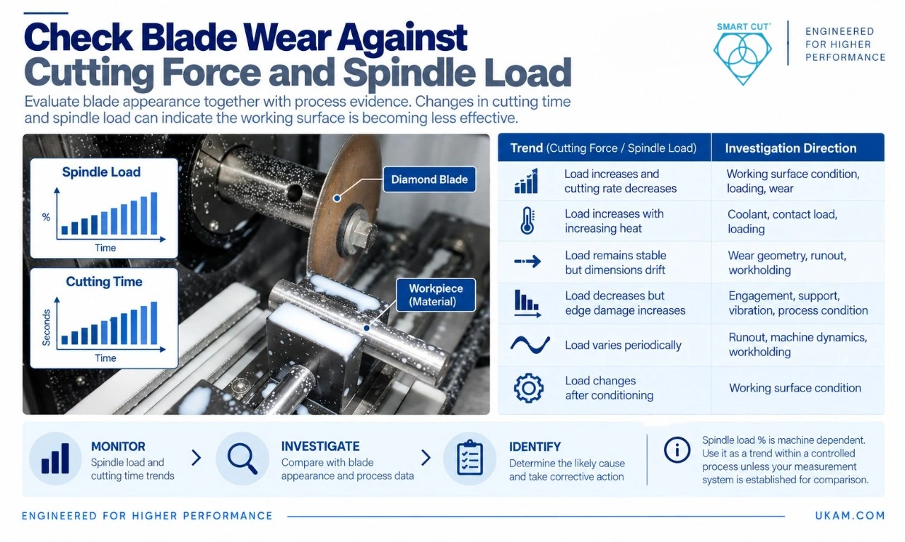
Blade appearance should be evaluated together with process evidence.
If cutting time increases while spindle load also increases, the working surface may be becoming less effective.
If cutting time increases without a corresponding load increase, the investigation may need to include material changes, feed control, machine behavior, or measurement variation.
|
Trend |
Investigation direction |
|---|---|
|
Load increases and cutting rate decreases |
Working surface condition, loading, wear |
|
Load increases with increasing heat |
Coolant, contact load, loading |
|
Load remains stable but dimensions drift |
Wear geometry, runout, workholding |
|
Load decreases but edge damage increases |
Engagement, support, vibration, process condition |
|
Load varies periodically |
Runout, machine dynamics, workholding |
|
Load changes after conditioning |
Working surface condition |
Spindle load percentage is not automatically comparable between different machines.
The display value depends on the machine and control system.
Use it primarily as a trend within a controlled process unless the measurement system has been established for comparison.
Check Coolant Before Blaming the Blade
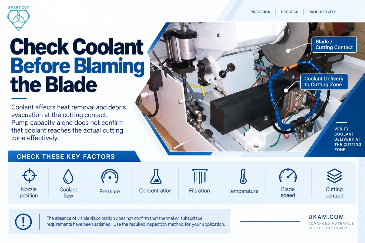
Coolant affects heat removal and debris evacuation at the cutting contact.
Pump capacity alone does not establish whether coolant reaches the actual grinding or cutting zone effectively.
Record:
- Nozzle position
- Coolant flow
- Pressure
- Concentration
- Filtration
- Temperature
- Blade speed
- Cutting contact
|
Wear or production pattern |
Coolant investigation |
|---|---|
|
Loading increases with temperature |
Delivery and flow |
|
Cutting rate decreases as heat rises |
Contact cooling |
|
Surface condition changes after coolant adjustment |
Delivery effectiveness |
|
Debris accumulates near cutting zone |
Flow direction and filtration |
|
Different machines produce different wear |
Machine specific coolant delivery |
The absence of visible discoloration does not establish that thermal or subsurface requirements have been satisfied.
Where material integrity matters, inspection should be based on the acceptance method required by the application.
Investigate Material Changes Before Changing Blade Specification
A diamond blade can behave differently when the work material changes even if the material name remains the same.
Record:
- Material grade
- Hardness
- Heat treatment where applicable
- Reinforcement
- Coating
- Thickness
- Microstructure
- Production condition
- Surface condition
For composite materials, reinforcement type and orientation can materially affect wear.
For ceramics and semiconductor materials, grade, structure, thickness, and surface condition can change fracture behavior.
| Material group |
Wear or cutting issue to investigate |
|---|---|
|
Silicon carbide |
Rapid abrasive demand and edge breakout |
|
Alumina |
Grain related edge damage |
|
Thermal cracking and surface damage |
|
|
Loading and accelerated blade wear |
|
|
Sapphire |
Edge breakout at entry or exit |
|
Fused silica |
Microcracking |
|
Gallium arsenide |
Edge damage and dimensional control |
|
PCD |
High abrasive demand and accelerated wear |
|
Fiber pullout, fuzzing, or matrix damage |
|
|
Metal matrix composites |
Accelerated abrasive wear |
The material label alone does not establish the correct blade specification.
The actual failure mechanism should determine the next verification.
Use the Location of Damage to Narrow the Investigation
The position of damage on the workpiece can provide useful evidence.
For example, damage concentrated at entry is different from damage occurring at breakthrough.
|
Damage location |
First checks |
|---|---|
|
Entry edge |
Alignment, initial engagement, runout, support |
|
Exit edge |
Breakthrough feed, remaining material, support |
|
Both edges |
Entry and exit conditions, blade stability |
|
Entire section |
Blade specification, coolant, material interaction |
|
One side |
Axial runout, alignment, workholding |
|
Random locations |
Vibration, material variation, unstable process |
|
Repeating locations |
Runout or machine dynamics |
The location of damage does not identify one cause by itself.
It narrows the investigation.
The next step should be a measurement or controlled comparison that can distinguish between the remaining possibilities.
Do Not Change Grit, Bond, Concentration, RPM, and Feed Together
A common troubleshooting mistake is to change several variables because the blade is performing poorly.
For example:
- Change from coarse to fine diamond
- Increase concentration
- Change bond
- Reduce feed
- Increase RPM
- Increase coolant
The production result may improve.
But the trial does not establish which change produced the improvement.
|
Problem |
Weak troubleshooting approach |
Better investigation |
|---|---|---|
|
Rapid blade wear |
Increase concentration immediately |
Check material, bond, grit, load and wear trend |
|
Poor edge quality |
Select finer grit only |
Check grit, runout, support, feed and breakthrough |
|
Loading |
Increase cutting pressure |
Check material, bond, coolant and blade condition |
|
Slow cutting |
Increase RPM immediately |
Check abrasive exposure, loading, bond and process |
|
Excessive heat |
Reduce feed only |
Check coolant, contact load, loading and blade condition |
|
Uneven wear |
Replace blade immediately |
Measure mounted runout and wear pattern |
Change one major variable at a time where practical.
When variables interact strongly, use a planned experiment rather than assuming one variable is responsible.
Compare Conditioning Response With Blade Wear
Conditioning can be useful evidence during troubleshooting.
Record the blade condition before conditioning, the conditioning method, and the production result afterward.
|
Before conditioning |
After conditioning |
Interpretation |
|---|---|---|
|
High load |
Lower load |
Working surface condition contributed |
|
Slow cutting |
Faster cutting |
Abrasive exposure may have limited performance |
|
High heat |
Lower heat |
Cutting efficiency may have improved |
|
Same cutting rate |
No meaningful change |
Investigate other process factors |
|
Quality remains poor |
Quality unchanged |
Conditioning was not sufficient evidence for the production failure |
A temporary improvement after conditioning does not prove that the bond specification is wrong.
It establishes that the working surface condition affected the process.
Further trials are required to determine whether the underlying cause is bond behavior, abrasive specification, material interaction, process load, coolant, or conditioning practice.
Define Useful Blade Life From Accepted Production
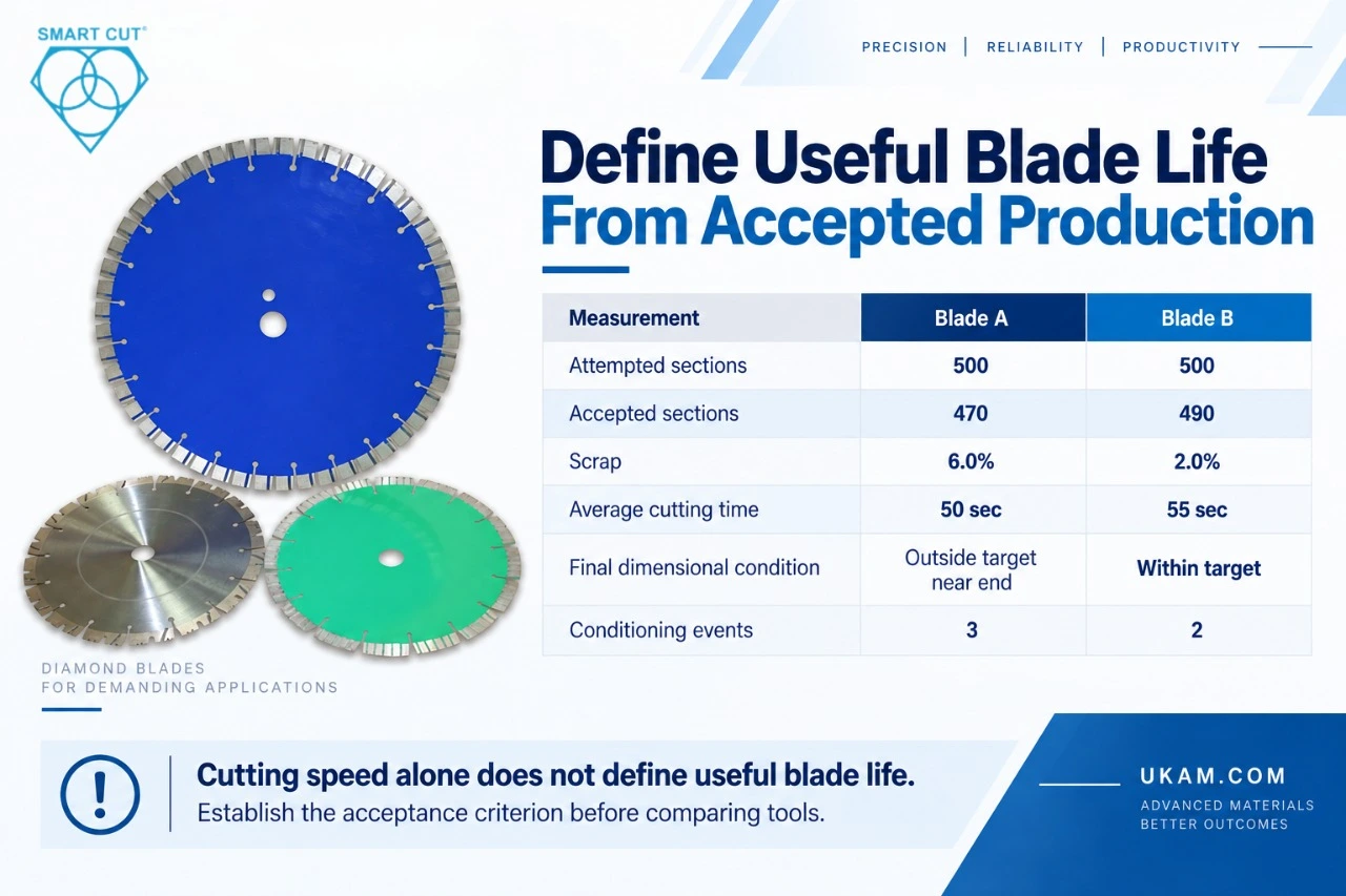
Blade life should be measured using the production requirement.
Consider two blades:
|
Measurement |
Blade A |
Blade B |
|---|---|---|
|
Attempted sections |
500 |
500 |
|
Physically cuts |
Yes |
Yes |
|
Accepted sections |
470 |
490 |
|
Scrap |
6.0% |
2.0% |
|
Average cutting time |
50 sec |
55 sec |
|
Final dimensional condition |
Outside target near end |
Within target |
|
Conditioning events |
3 |
2 |
Blade A cuts faster.
Blade B produces more accepted sections.
This illustrative example does not establish that Blade B is preferable for an actual application. It demonstrates why cutting speed alone cannot define useful blade life.
The acceptance criterion must be established before comparing tools.
Compare Cost Per Acceptable Section
Blade price does not represent total production cost.
A useful calculation is:
Cost per acceptable section = Total evaluated process cost ÷ Final accepted sections
The cost boundary can include:
- Blade cost
- Machine time
- Labor
- Conditioning
- Coolant
- Setup
- Tool changes
- Inspection
- Rework
- Scrap
- Material loss
- Downtime
Illustrative example only
The following numbers are hypothetical and are not UKAM production data or performance benchmarks.
|
Cost factor |
Blade A |
Blade B |
|---|---|---|
|
Blade cost |
$180 |
$240 |
|
Attempted sections |
1,000 |
1,000 |
|
Accepted sections |
950 |
980 |
|
Cutting time per section |
55 sec |
62 sec |
|
Conditioning cost |
$180 |
$120 |
|
Setup and changes |
$150 |
$150 |
|
Machine and labor cost |
$1,833 |
$2,067 |
|
Total evaluated cost |
$2,343 |
$2,577 |
|
Cost per accepted section |
$2.47 |
$2.63 |
The calculation shows why blade price, cutting time, tool life, scrap, and conditioning need to be evaluated together.
If material value is high, actual kerf and material loss should also be included.
Qualify the Blade After the Wear Mechanism Is Identified
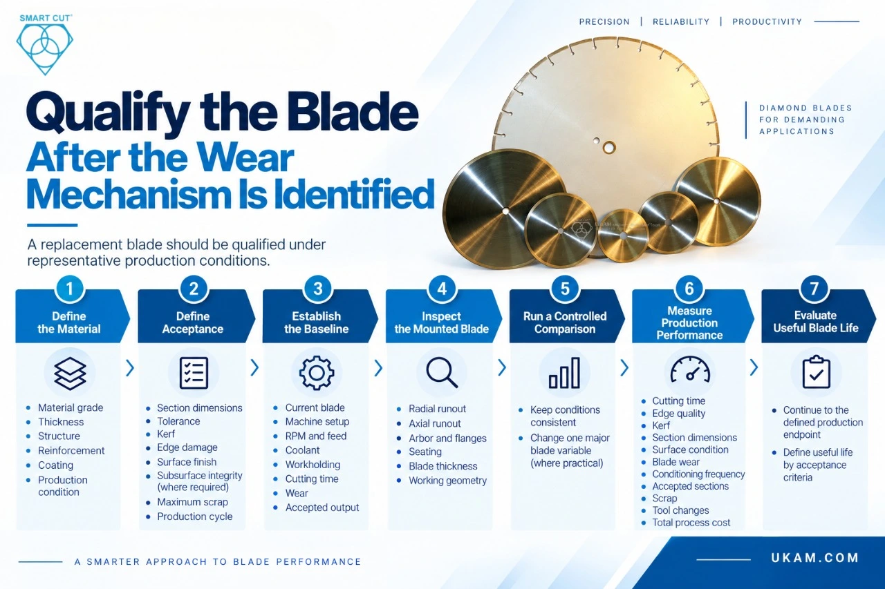
A replacement blade should be qualified under representative production conditions.
Phase 1: Define the material
Record the exact material grade, thickness, structure, reinforcement, coating, and production condition.
Phase 2: Define acceptance
Specify:
- Section dimensions
- Dimensional tolerance
- Kerf
- Edge damage
- Surface finish
- Subsurface integrity where required
- Maximum scrap
- Production cycle requirement
Phase 3: Establish the baseline
Record the current blade, machine, mounting, RPM, feed, coolant, workholding, cutting time, wear, and accepted output.
Phase 4: Inspect the mounted blade
Measure relevant radial and axial runout.
Check arbor, flanges, seating, blade thickness, and working geometry.
Phase 5: Run a controlled comparison
Keep material, machine, workholding, coolant, and inspection method consistent.
Change one major blade variable where practical.
Phase 6: Measure production performance
Track:
- Cutting time
- Edge quality
- Kerf
- Section dimensions
- Surface condition
- Blade wear
- Conditioning frequency
- Accepted sections
- Scrap
- Tool changes
- Total process cost
Phase 7: Evaluate useful blade life
Continue the trial until the defined production endpoint is reached.
Do not define blade life simply by whether the blade can still cut.
Ask What the Wear Pattern Actually Proves
A good troubleshooting investigation separates evidence from conclusions.
|
Finding |
What it may support |
What it does not establish |
|---|---|---|
|
Blade is glazed |
Working surface condition changed |
Exact reason for glazing |
|
Conditioning restores cutting |
Working surface condition contributed |
Correct bond specification by itself |
|
One side is worn |
Uneven engagement |
Spindle defect by itself |
|
Loading is visible |
Material accumulation occurred |
Incorrect grit alone |
|
Cutting time increases |
Cutting efficiency decreased |
Blade specification is solely responsible |
|
Diameter decreases rapidly |
Accelerated dimensional wear |
Incorrect concentration alone |
|
Edge damage increases |
Process quality degraded |
Finer grit is automatically required |
|
Runout changes after remounting |
Mounting contributed |
Blade geometry is acceptable |
|
Load increases over blade life |
Process resistance increased |
Specific wear mechanism without other evidence |
|
Scrap increases with blade age |
Useful production life may have ended |
Physical blade failure is the only cause |
This distinction prevents a common troubleshooting error: turning an observation into a diagnosis before the supporting evidence has been collected.
Evaluate Diamond Blade Construction as Part of the Investigation
Diamond abrasive size is only one component of blade design.
The investigation may need to consider:
|
Variable |
What to investigate |
|---|---|
|
Diamond type |
Compatibility with work material and operation |
|
Cutting interaction and required section quality |
|
|
Concentration |
Abrasive content and working surface behavior |
|
Bond |
Abrasive retention and wear behavior |
|
Blade thickness |
Kerf, stiffness, and material loss |
|
Diameter |
Machine compatibility and operating condition |
|
Geometry |
Engagement and required cut |
|
Mounting |
Arbor and flange compatibility |
|
Working layer |
Wear and exposure mechanism |
|
Conditioning |
Permitted method and frequency |
Diamond concentration should be recorded separately from diamond size.
A change in concentration can change abrasive distribution and load sharing. It should not automatically be interpreted as a grit effect.
Similarly, a bond change can alter abrasive exposure and wear behavior even when the diamond specification remains unchanged.
Use the Wear Pattern to Decide the Next Measurement
The purpose of troubleshooting is not to collect every possible measurement.
The purpose is to collect the measurement that can distinguish between the remaining causes.
|
Primary observation |
Next measurement |
|---|---|
|
Glazing |
Cutting rate before and after appropriate conditioning |
|
Loading |
Blade surface condition and coolant delivery |
|
Uneven side wear |
Axial runout and flange condition |
|
Circumferential wear variation |
Radial runout and mounting condition |
|
Rapid diameter loss |
Diameter versus accepted section count |
|
Increasing kerf |
Actual kerf versus blade wear and runout |
|
Increasing edge damage |
Entry, steady cut, and exit condition |
|
Increasing heat |
Coolant delivery, load, blade condition |
|
Slow cutting |
Cutting time, load trend, abrasive exposure |
|
Wear differs between machines |
Machine, mounting, coolant and workholding |
|
Wear changes after remounting |
Mounted runout and seating |
|
Wear continues despite conditioning |
Material, machine and blade construction |
This approach keeps the troubleshooting process measurable.
Common Diamond Blade Wear Troubleshooting Mistakes
Mistake 1 — Replacing the blade without inspecting it
The old blade contains useful evidence.
Better approach: Photograph and inspect the working surface, wear distribution, loading, edge condition, and mounting condition before disposal.
Mistake 2 — Treating every smooth blade surface as glazing
A smooth appearance can have multiple explanations.
Better approach: Compare cutting rate, heat, load, abrasive exposure, and conditioning response.
Mistake 3 — Increasing pressure against a loaded blade
Additional force may increase heat and mechanical stress.
Better approach: Investigate material accumulation, coolant, bond behavior, and chip evacuation.
Mistake 4 — Measuring only blade diameter
Diameter does not describe side wear, runout, profile condition, or edge integrity.
Better approach: Measure the feature that corresponds to the production failure.
Mistake 5 — Measuring runout only at the arbor
The arbor may be acceptable while the working section has different runout.
Better approach: Measure the complete mounted assembly and, where practical, the working section.
Mistake 6 — Selecting a blade from one wear symptom
Loading does not automatically mean concentration is wrong.
Glazing does not automatically mean grit is wrong.
Rapid wear does not automatically mean a higher concentration is required.
Better approach: Identify the mechanism, collect evidence, then select the next variable to investigate.
Mistake 7 — Changing multiple process variables simultaneously
The result becomes difficult to interpret.
Better approach: Establish a baseline and change one major variable where practical.
Mistake 8 — Defining tool life by physical survival
A blade can continue cutting after production quality has failed.
Better approach: Define useful life from accepted production.
Record the Wear Investigation So It Can Be Repeated
A troubleshooting result is much more valuable when another engineer can reproduce the investigation.
|
Record |
Required information |
|---|---|
|
Material |
Exact grade and condition |
|
Part |
Geometry and thickness |
|
Blade |
Diameter, thickness, abrasive, grit, concentration, bond |
|
Machine |
Manufacturer and model |
|
Mounting |
Arbor, flanges and seating |
|
Runout |
Measurement location and result |
|
RPM |
Actual operating value |
|
Feed |
Actual operating value |
|
Coolant |
Type, flow, pressure and delivery |
|
Workholding |
Fixture and support |
|
Wear pattern |
Description and photographs |
|
Cutting rate |
Initial and final |
|
Quality |
Dimensions, kerf, finish and edge condition |
|
Tool life |
Accepted sections |
|
Conditioning |
Method and frequency |
|
Scrap |
Rejected output |
|
Cost |
Defined process cost |
|
Result |
Pass, fail or inconclusive |
|
Next action |
Specific investigation or controlled change |
Record the result as Pass, Fail, or Inconclusive.
An inconclusive result is useful if the next investigation is clearly defined.
Diamond Blade Wear Qualification Checklist
Before approving a blade for production, verify:
Material
- Exact material grade recorded
- Material condition verified
- Thickness recorded
- Reinforcement or structure recorded where applicable
Process
- Coolant reaches the cutting zone
- Coolant condition recorded
- Cutting time measured
- Conditioning method recorded where applicable
- Blade wear measured during production
Blade
- Diameter recorded
- Thickness recorded
- Actual kerf measured
- Diamond specification recorded
- Concentration recorded
- Bond construction recorded
- Working surface inspected
Machine
- Actual RPM recorded
- Feed recorded
- Arbor verified
- Flanges inspected
- Mounted runout measured
- Machine rigidity considered
- Workholding verified
Quality
- Section dimensions measured
- Kerf measured
- Edge condition inspected
- Surface finish measured where required
- Subsurface integrity evaluated where required
- Scrap recorded
Production
- Accepted sections recorded
- Useful blade life defined
- Tool changes recorded
- Conditioning frequency recorded
- Cost per acceptable section calculated
- Trial repeated under representative conditions
Frequently Asked Questions
Yes. Blade performance depends on the complete system. Machine speed range, spindle condition, mounting, runout, rigidity, coolant delivery, workholding, and available process control can change how the blade behaves. A blade that performs acceptably on one machine should therefore be qualified before being transferred to another machine.
No. The first question is whether the construction permits an appropriate conditioning method and whether conditioning restores the required cutting behavior. If cutting performance returns after conditioning, that provides evidence that the working surface condition contributed. The result does not by itself establish the original cause of glazing.
No. Physical abrasive wear should be compared with production requirements. A blade may still have visible abrasive material while producing excessive kerf, poor edge quality, unacceptable dimensions, or excessive cutting time. Useful blade life should be based on accepted production.
Not necessarily. Concentration is only one part of the blade construction. Rapid wear may also involve material abrasiveness, bond behavior, diamond size, contact conditions, coolant, machine stability, and operating conditions. Concentration should be evaluated with the rest of the blade specification.
The machine changes the physical cutting environment. Mounting condition, runout, spindle dynamics, coolant delivery, rigidity, workholding, actual RPM, and feed can all affect blade engagement. Compare the complete process before concluding that the blade itself is inconsistent.
No. Slower cutting can result from abrasive wear, glazing, loading, bond behavior, coolant problems, changed material, excessive contact load, or machine conditions. Compare cutting rate with blade condition, load, heat, coolant, and material condition before changing the abrasive specification.
Possibly, depending on the degree and location of wear and the production tolerance. The correct question is whether the wear has changed the working geometry enough to affect the defined acceptance criteria. Measure the part and blade rather than judging the blade from appearance alone.
No. Material grade, thickness, condition, machine, operation, kerf requirement, edge requirement, coolant, and production target can change the required tooling configuration. Material name alone is not sufficient for a production qualification.
No. Surface finish is only one quality characteristic. A process can produce an acceptable Ra value while still producing dimensional variation, edge damage, subsurface damage, excessive kerf, thermal effects, or unstable tool life. Acceptance should include every quality requirement that matters to the component.
Provide the exact material and condition, workpiece thickness, section geometry, dimensional tolerance, kerf requirement, edge requirement, surface finish requirement, current blade specification, machine model, arbor and flange arrangement, actual RPM, feed, coolant delivery, workholding, runout, cutting time, current blade life, conditioning practice, failure pattern, scrap rate, and inspection results.
Request a Diamond Blade Evaluation
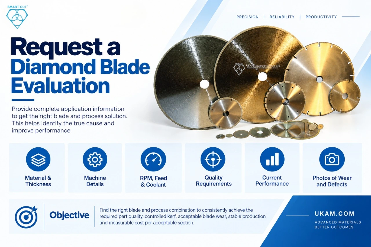
If a diamond blade is showing glazing, loading, uneven wear, rapid wear, increasing kerf, excessive heat, slow cutting, edge damage, or unstable production, provide the complete application information rather than only the blade diameter.
Useful information includes:
- Exact material grade and condition
- Workpiece thickness
- Required section dimensions
- Dimensional tolerance
- Maximum permitted edge damage
- Surface finish requirement
- Kerf requirement
- Current blade diameter and thickness
- Diamond size and concentration
- Bond construction
- Machine model
- Arbor and flange configuration
- Actual RPM and feed
- Coolant type and delivery
- Workholding arrangement
- Mounted runout
- Cutting time
- Number of accepted sections
- Conditioning frequency
- Blade wear pattern
- Scrap or rejection rate
- Photos of the worn blade and resulting defects
UKAM manufactures standard and custom diamond and CBN tooling configurations. Application specific evaluation can include abrasive specification, grit, concentration, bond, blade geometry, dimensions, mounting, and production requirements.
The objective should not be simply to find another blade that cuts.
The objective is to identify a blade and process combination that repeatedly produces the required part quality while maintaining controlled kerf, acceptable blade wear, stable production, and measurable cost per acceptable section.
Trusted by Tens of Thousands of Manufacturers, Laboratories,
Research Institutions Worldwide Since 1990
American Based Manufacturer
Established in 1990
