








































Diamond Tool Troubleshooting for Precision Manufacturing

Table of Contents
Toggle
American Based Manufacturer

Established in 1990


Custom manufacturing


Identify causes and verify corrective actions in precision machining
Overheating, chipping, slow cutting, inconsistent dimensions, and short tool life can originate in the tool, the machine, or the process. A tool defect, an unsuitable specification, and a setup problem can all produce similar symptoms. Your investigation should keep each possibility open until measurements support a cause.
This guide explains how to investigate common problems with diamond blades, core drills, and grinding wheels. Start by making the condition safe, documenting the failure, and checking the most likely causes. Then test a corrective action against defined quality and production requirements. For general handling and setup fundamentals before you troubleshoot, review how to properly use diamond tools.
Follow a Controlled Troubleshooting Sequence
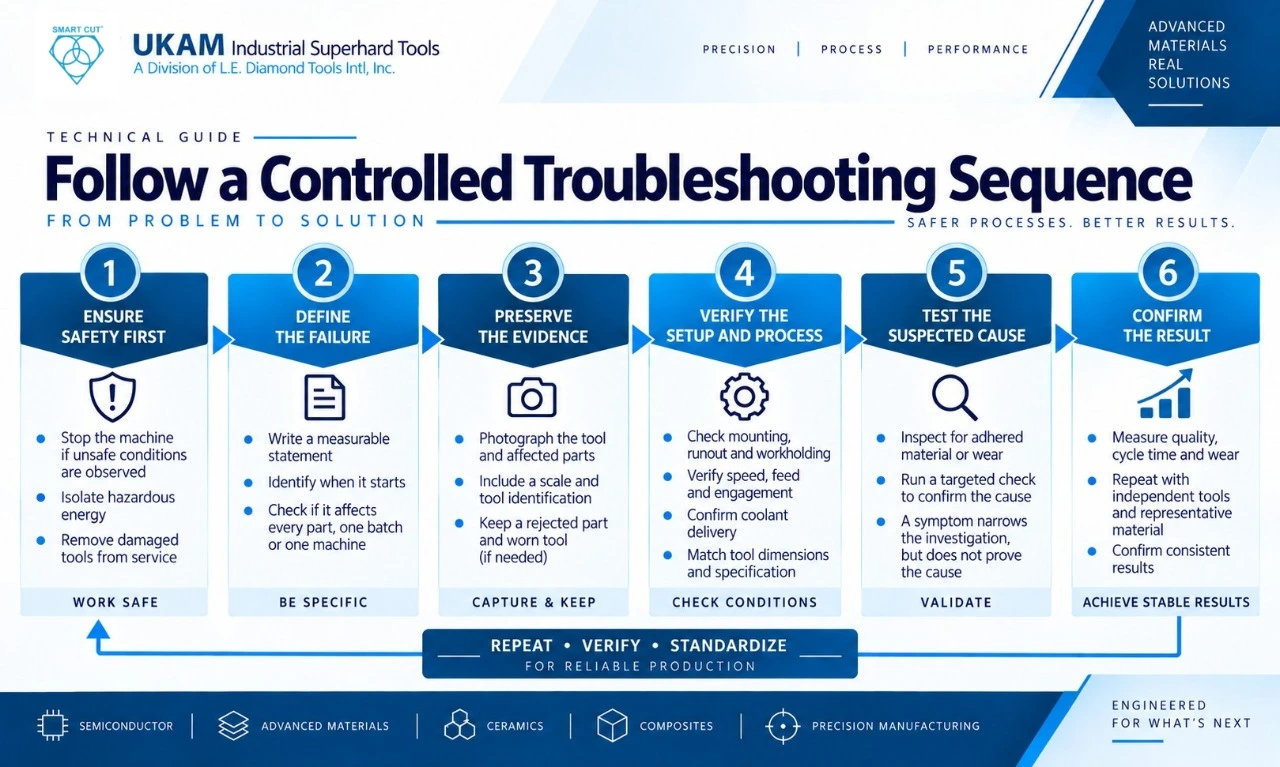
Stop the machine if you observe damage, severe vibration, abnormal noise, or loss of control. Isolate hazardous energy before hands-on inspection, clearing a blockage, or changing the mounting assembly. Remove cracked, deformed, or otherwise damaged tools from service. Follow the tool and machine instructions, including guarding and maximum operating speed — the same sequencing discipline covered in diamond core drilling best practices for speed and accuracy.
1. Define the Failure
Write a measurable statement. For example, record that exit chipping exceeds the drawing limit after 180 accepted holes. Identify when the problem starts and whether it affects every part, one material batch, or one machine. A clear failure definition is the same starting point used when qualifying a diamond and CBN blade specification for a new application.
2. Preserve the Evidence
Photograph the tool and affected parts before cleaning or conditioning. Include a scale, consistent lighting, and tool identification. Retain a representative rejected part and the worn tool when further analysis may be needed.
3. Verify the Setup and Process
Check mounting, runout, workholding, actual speed, feed, engagement, and coolant delivery. Compare measured conditions with the last acceptable setup. Verify the tool dimensions and specification against the order or drawing — the setup checks described in how to properly use precision diamond drills apply directly here.
4. Test the Suspected Cause
Select a check that can distinguish between explanations. For example, inspect for adhered material before attributing slow cutting to dull abrasive. A symptom narrows the investigation but does not prove a cause. This is especially true across bond types; see how diagnostic priorities shift by construction in metal bond diamond and CBN wheels.
5. Change a Justified Variable
Make one documented adjustment where practical and keep other conditions controlled. Use a planned experiment when several variables interact. Every trial must remain within the approved operating limits described in how to select a diamond/CBN grinding wheel.
6. Confirm the Result
Measure quality, cycle time, wear, and accepted output after the change. Repeat promising conditions with independent tools and representative material. A temporary improvement identifies a useful direction but does not establish a permanent solution — the same confirmation standard used in our complete diamond core drill guide.
Record a Reproducible Production Baseline
Use the same record for the reference process and each trial. Programmed values alone are insufficient when actual machine or coolant conditions differ, whether you’re running core drills or precision blades.
|
Record |
Information to Capture |
|---|---|
|
Work material and part |
Exact grade, batch, thickness, condition, feature dimensions, and support arrangement. |
|
Tool |
Identification, abrasive type, diameter, thickness or wall thickness, grit designation, bond, concentration where applicable, and geometry. |
|
Machine and mounting |
Machine, spindle, arbor, flange or collet arrangement, tool overhang, and measured runout at a defined location. |
|
Operating conditions |
Actual RPM, feed with units, depth or engagement, and stock removed. Record changes during entry and breakthrough. |
|
Coolant and conditioning |
Fluid, concentration, temperature where relevant, flow, pressure measurement location, nozzle position, and conditioning history. |
|
Acceptance and output |
Dimensional limits, chipping limits, finish, inspection method, cycle time, accepted and rejected parts, and tool end-of-life criterion. |
For rotating tools, record tool diameter as well as RPM. Surface speed depends on both. The same RPM does not give the same surface speed on different diameters. Record grit designation systems and micron size where available so unlike specifications — as explained in selecting the right diamond blade for your application — are not treated as equivalent.
Use Failure Timing to Choose the First Check
|
Observed Pattern |
First Verification |
What the Finding May Justify |
|---|---|---|
|
Problem starts immediately |
Check the supplied tool, mounting, initial conditioning requirements, process load, and coolant access. |
Correct a verified mismatch or setup error before a further trial. |
|
Performance declines gradually |
Compare surface deposits, abrasive condition, dimensions, and cycle time with the initial condition. |
Evaluate construction-specific cleaning, conditioning, or a revised wear limit. |
|
Problem follows one change |
Verify the changed material, setting, fluid, fixture, or tool lot against the prior record. |
Run a controlled comparison using a suitable reference condition. |
|
Only one machine is affected |
Compare runout, mounting, stiffness, coolant, and actual operating conditions. |
Correct the measured machine or setup difference and repeat the comparison. |
Several causes can coexist. Correcting coolant delivery may reduce heat while a mounting error still causes chipping. Continue checking every acceptance requirement after an improvement — a pattern documented in detail in our diamond drills guide.
Distinguish Loading, Glazing, and Abrasive Wear
Loading is the accumulation of work material or debris on the abrasive surface and in the spaces needed for chip clearance. Glazing describes a dull working condition, often involving flattened abrasive edges or insufficient renewal of cutting points. Abrasive wear also includes fracture and loss of grains. These conditions can occur together, as detailed in why diamond grinding wheels glaze and how to restore cutting performance.
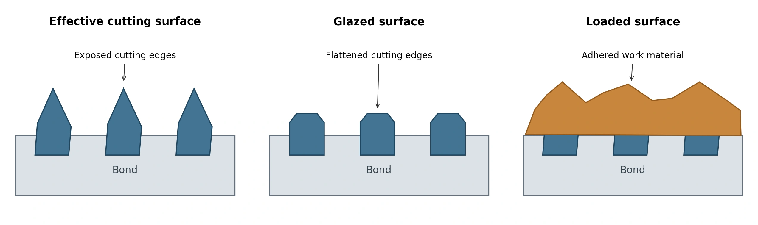
Simplified schematic of working surface conditions. Actual abrasive shape, spacing, and exposure vary with tool construction. The illustrations are not tool inspection photographs.
Inspect a safely stopped tool under suitable magnification. Compare the same area before and after an approved cleaning or conditioning procedure. Deposits support a loading diagnosis. Flattened cutting points and reduced cutting action may support a glazing diagnosis. Appearance alone may be inconclusive.
If cleaning removes deposits and performance improves, investigate chip clearance, coolant access, and material interaction. If dressing an eligible tool restores cutting action, review abrasive renewal and the dressing interval using SMART CUT® dressing sticks. Neither result proves that the bond specification alone caused the problem.
Correct Slow Cutting Without Forcing the Tool
Separate slow cutting from first use from a gradual decline. For a new tool, verify the delivered specification, rotation direction where specified, permitted initial conditioning, actual feed, and surface speed. Check for rubbing caused by misalignment or insufficient clearance — especially relevant when selecting grit size, as covered in our diamond and CBN wafering blade selection guide.
For a used tool, compare cycle time and spindle load with the baseline. Inspect for loading, dull abrasive, loss of working diameter, and restricted coolant flow. Use the same machine when comparing load percentage. Displayed percentages from different machines are not directly equivalent.
If loading is confirmed, address the deposit and its cause before raising feed. If an eligible tool responds to conditioning but quickly slows again, review the interval and tool construction with the manufacturer. Increasing force against a tool that has lost cutting action can add heat and mechanical load.
Investigate Overheating at the Cutting Zone
Heat generation can exceed removal because of excessive engagement, rubbing, dull abrasive, unsuitable operating conditions, or inadequate cooling. Record when the problem begins and what changed. Discoloration and a visually acceptable surface do not provide a complete assessment of thermal damage.
|
Check |
Evidence to Collect |
Conditional Corrective Action |
|---|---|---|
|
Coolant access |
Observe delivery through the approved guarded viewing arrangement. Check whether coolant reaches the contact zone. |
If the stream misses the interface, correct nozzle position or delivery using the approved setup procedure. |
|
Coolant circuit |
Check filters, nozzles, internal passages, fluid concentration, and measured delivery at relevant points. |
If a restriction or fluid error is confirmed, restore the specified condition and repeat the trial. |
|
Process load |
Compare actual feed, engagement, stock removal, and load with the acceptable baseline. |
If load increased, restore the qualified condition or trial a justified adjustment within approved limits. |
|
Tool condition |
Inspect deposits, cutting edges, working dimensions, and abnormal wear. |
If the tool is eligible, use the specified cleaning or conditioning method. Replace a damaged tool. |
Pump flow and pressure do not establish how much coolant reaches the abrasive contact. Record where each value is measured. A higher pump setting may leave the cutting zone poorly supplied if delivery is obstructed or misdirected — this is exactly the coolant-delivery mechanism engineered into machines like the SMART CUT® 6035 precision cutting saw.
Do not automatically reduce RPM whenever heat appears. Review diameter, surface speed, feed, engagement, and tool condition together. For a qualified dry process, follow its specified extraction, cooling, and duty-cycle requirements.
For fluid options, see SMART CUT® coolants for diamond tools.
Reduce Workpiece Edge Chipping
Workpiece chipping means damage to the component edge. It differs from fracture or damage to the tool itself. Measure the largest chip and its location using a defined inspection method. Record entrance and exit damage separately — a distinction worked through in full in how to select a diamond blade for 99.5% alumina ceramic without edge chipping.
|
Damage Location |
How to Verify the Cause |
Action Supported by the Finding |
|---|---|---|
|
Entry edge |
Inspect initial contact, entry feed, runout, and part restraint. |
If impact or movement occurs at entry, correct the setup or qualify a controlled entry feed. |
|
Exit edge or breakthrough |
Photograph both faces. Check remaining support and feed as the tool exits. |
If breakout follows loss of support, qualify suitable backing, support, or a breakthrough feed change. |
|
One side or periodic positions |
Compare the pattern with measured runout, blade movement, and fixture contact. |
If a mechanical error is confirmed, correct it before changing grit. |
|
Random locations |
Compare material batches, pre-existing defects, clamping, coolant, and tool condition. |
Isolate the variable associated with rejected parts and repeat under controlled conditions. |
If the setup is stable and chipping remains unacceptable, evaluate grit, tool geometry, bond, feed, and engagement as a controlled tooling trial. A finer grit may improve edge quality, but you must also verify cutting rate, heat, and loading behavior. Base feed adjustments on tool instructions and measured results.
For drilling setup considerations, see what to check before you buy a diamond core drill.
Resolve Inconsistent Dimensions and Hole Diameter
First verify the measurement. Check instrument suitability, calibration status, measurement temperature where relevant, and whether the same method is used for accepted and rejected parts. Measure several holes at defined depths and angular positions when the tolerance requires it.
Check the tool working diameter and geometry before and after the trial. Measure spindle and arbor runout at defined surfaces. Where the tool design permits, also verify the mounted assembly. Compare the measurements with the tool and machine instructions and your qualified process limits — the same construction reference used across SMART CUT® diamond and CBN wheels.
An oversized hole from the first part warrants checks of tool diameter, mounting, runout, and lateral movement. A diameter trend during production warrants checks of wear, deposits, deflection, temperature, and measurement consistency. Hole taper or out-of-roundness needs more than a single entrance measurement.
If the problem follows a tool across controlled setups, investigate its geometry and specification. If it follows one machine, investigate that machine and its mounting system. Neither observation alone establishes the final cause.
Check Precision Blade Deflection and Kerf Variation
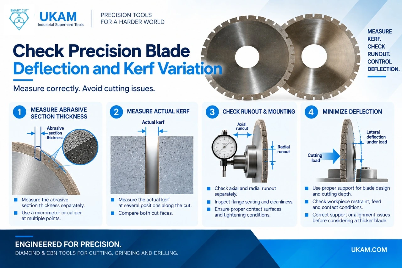
Measure the abrasive section thickness and the actual kerf separately. Blade movement, side contact, and edge breakout can make a slot appear wider than the cutting section — the exact deflection behavior engineered against in a SMART CUT® Series 305M precision blade. Measure below damaged edges where the inspection specification permits. Record kerf at several positions along the cut and compare both cut faces.
Check axial runout, which describes side-to-side deviation, separately from radial runout. Use the specified measurement surfaces and record the indicator location. Inspect flange seating, cleanliness, contact surfaces, and approved tightening conditions. Extra tightening torque is not a remedy for a seating error — tight runout tolerances like those held on precision ultra-thin blades for gang saw machines depend on correct seating, not added torque.
Match flange or stiffener support to the blade design, cutting depth, and machine instructions. If lateral deflection appears under load, investigate unsupported blade exposure, feed, workpiece restraint, and contact conditions. One-sided wear or rubbing marks can help locate unwanted side contact. Correct a verified support or alignment problem before evaluating a thicker blade, which also changes kerf and material loss.
Investigate Vibration and Poor Surface Finish
Record whether vibration starts during unloaded rotation, initial contact, full engagement, or a particular speed range. Stop a severe or abnormal vibration condition. Inspect seating surfaces, the arbor, flange or collet arrangement, workholding, tool overhang, and damage before another run — the same mounting checks that apply to SMART CUT® 100DE series core drills.
If contamination prevents full seating, clean and reassemble according to the approved procedure, then recheck runout. If vibration appears only under cutting load, investigate deflection, engagement, restraint, and cutting condition. Persistent spindle or bearing concerns require qualified machine inspection.
For poor finish, record roughness with the specified parameter and measurement direction. Compare repeating marks, isolated scratches, and general roughness separately. Repeating patterns can direct attention to vibration or rotational errors. Isolated scratches warrant checks for debris, damaged abrasive, and material contamination.
If the machine and mounting are stable, investigate grit, working surface condition, feed, and conditioning. A low roughness value does not by itself establish freedom from subsurface cracks or thermal damage. Use the inspection method required by the component specification.
Measure Wear Against Useful Tool Life
Define tool life as accepted output before a stated limit is reached. That limit may be diameter, kerf, edge damage, roughness, form, cycle time, or another functional requirement. Record wear measurements and quality at consistent intervals, using a construction such as sintered metal bond diamond and CBN dicing blades as your reference baseline.
If working dimensions fall rapidly, compare material abrasiveness, engagement, abrasive retention, and conditioning consumption. If one side wears faster, investigate alignment, side contact, support, and coolant distribution. A tool with substantial abrasive remaining may still have reached its useful production limit.
Separate abrasive consumed by machining from material removed during dressing or truing. Frequent conditioning can reduce production capacity even when each conditioning event restores cutting. Review the complete pattern before selecting a different bond or concentration.
Match Conditioning to Tool Construction
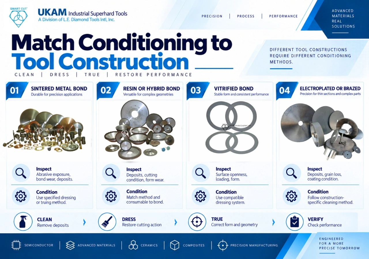
Cleaning removes adhered contamination. Dressing restores the abrasive working condition. Truing corrects geometry or running form. Some procedures combine these functions. Truing does not automatically establish balance, and cleaning cannot replace missing abrasive — the distinctions covered in diamond dressers: types, applications, and best practices.
|
Construction |
What to Inspect |
Conditioning Decision |
|---|---|---|
|
Sintered metal bond |
Abrasive exposure, bond wear, deposits, and retained working dimensions. |
Use the specified dressing or truing method where applicable. Recheck geometry afterward. |
|
Resin or hybrid bond |
Deposits, cutting condition, form wear, and signs of local damage. |
Match the method and consumable to the exact bond and wheel design. Track stock removed — relevant when running diamond backgrinding wheels. |
|
Vitrified bond |
Working surface openness, loading, form, and damage. |
Use a compatible dressing system and qualified settings. Confirm restored form and cutting action, following the same edge-quality logic used for electroplated diamond edge grinding wheels. |
|
Electroplated or brazed |
Deposits, grain loss, coating condition, and damage to the body. |
Follow construction-specific cleaning instructions. Do not apply bulk-bond dressing methods unless expressly approved — see 5 tips to make electroplated diamond wheels last longer. |
Conventional single-layer plated and brazed tools do not contain a deep reserve of abrasive for repeated dressing. Specialized multilayer or other constructions require their own instructions. Identify the actual construction before attempting to restore performance.
When deposits obscure the abrasive, use approved cleaning first if the tool is otherwise serviceable. Reinspect before deciding whether dressing is needed. For an eligible bonded tool with dull cutting points, use a matched SMART CUT® 030DSM dressing stick and record dimensional loss. Stop conditioning when further removal would exceed the working allowance. Remove tools with structural damage or coating separation from service. Review substantial abrasive loss with the manufacturer. If restoration lasts only briefly, compare accepted output between conditioning events and investigate why the surface deteriorates again.
Apply the Checks in Worked Examples
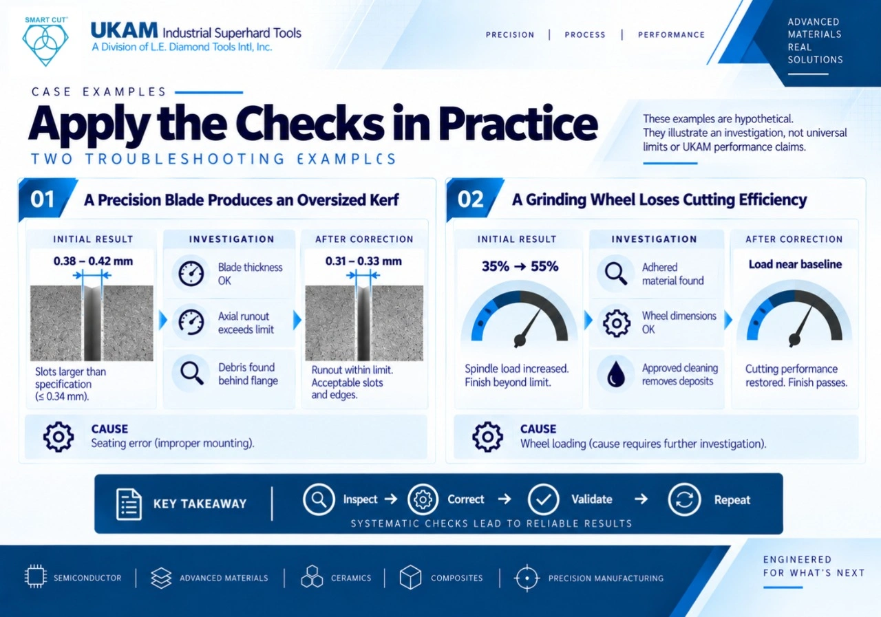
The following examples are hypothetical. Their dimensions and outcomes illustrate an investigation, not universal limits or UKAM performance claims — the same disclaimer that applies to the grinding-performance case studies in how diamond and CBN wheels improve grinding performance and reduce costs.
A Precision Blade Produces an Oversized Kerf
A blade with a 0.30 mm abrasive section produces slots measuring 0.38 to 0.42 mm against a 0.34 mm maximum. Measurements below the chipped edges confirm excessive slot width. The cutting section meets its thickness specification, but mounted axial runout exceeds the established process limit.
Inspection finds debris behind a flange. After cleaning and correct reassembly, runout returns within the process limit. A controlled trial using the same material, feed, and speed produces 0.31 to 0.33 mm slots with acceptable edges. These findings support a seating error as the cause. Repeat the check after another mounting cycle before considering the correction reproducible.
A Grinding Wheel Loses Cutting Efficiency
On the same machine and pass, displayed spindle load rises from a 35% baseline to 55%, and finish exceeds the permitted roughness. Inspection shows adhered material while wheel dimensions remain acceptable. Approved cleaning removes the deposits. Load returns near baseline and the finish passes.
Deposits return after similar output. This supports loading as a performance limitation but leaves its cause unresolved. Check coolant access, filtration, and material interaction. Trial one justified delivery correction, then compare accepted parts between cleaning events. Confirm finish and dimensional stability throughout the repeat run.
Account for Material-Specific Failure Mechanisms
A material name suggests possible mechanisms but does not establish one dominant failure. Grade, grain structure, porosity, crystal orientation, binders, and the machining operation can change the result — a factor built into how UKAM specifies fine wafering blades for delicate material applications.
|
Material |
Concerns to Investigate |
Useful Evidence |
|---|---|---|
|
Silicon carbide |
Tool wear, brittle fracture, loss of cutting rate, and surface or subsurface damage. |
Exact grade, removal conditions, wear trend, and the required integrity inspection. |
|
Alumina and silicon nitride |
Edge damage, abrasive wear, loading, and surface integrity. |
Entry and exit photographs, material grade, surface condition, and operating history. |
|
Tungsten carbide |
Grinding force, edge damage, heat, loading, and wheel wear. |
Carbide grade and binder content, coolant condition, wheel condition, and edge inspection. |
|
Sapphire |
Chipping, orientation-dependent behavior, surface damage, and tool wear. |
Crystal orientation where known, entry and exit damage, and dimensional results. |
|
Fused silica and gallium arsenide |
Edge breakout and surface or subsurface damage. |
Specified damage limits and a suitable inspection method. Surface photographs alone cannot establish subsurface integrity. |
|
PCD workpieces |
Cutting edge damage, grinding load, thermal effects, and interface damage where a carbide backing is present. |
PCD grade, backing construction, wheel condition, and functional edge acceptance. |
Apply material-specific handling and exposure controls using the safety data sheet and your facility procedures. This is particularly relevant when machining materials containing hazardous constituents — a consideration built into applications like diamond core drills and tools for the photonics industry.
Select a Revised Specification From the Evidence
Change the specification to address a measured limitation. Persistent glazing after setup and conditioning checks may justify reviewing abrasive renewal and bond behavior. Excessive wear may justify reviewing retention, concentration, grit, and operating load. Persistent edge damage may justify a different grit or geometry after mechanical causes are controlled — the same evidence-first logic covered in our precision ultra-thin diamond blade guide.
Changing concentration alone does not resolve every wear or heat problem. Bond, grit, abrasive properties, geometry, and process conditions interact. Confirm abrasive compatibility with the exact work material, especially when evaluating diamond and CBN alternatives, or when a job calls for a dedicated SMART CUT® 1050 precision cutting machine rather than a manual setup.
Validate the Correction Under Production Conditions
Define dimensional, surface, edge, cycle-time, and useful-life requirements before the trial. Include stopping conditions. Use representative material and retain a suitable reference process when one is available.
For a tool-only comparison, control the machine, material, workholding, coolant, inspection, and starting conditions where they suit both tools. If each tool requires different optimized settings, describe the result as a comparison of complete processes. Record every difference.
Repeat promising conditions with independent tools and representative batches. Do not choose a fixed number of trials without considering process variation and the consequence of failure. Verify the result after ordinary production interruptions or changes that matter to the application.
A trial ending after 100 accepted parts demonstrates performance over those 100 parts. It does not establish maximum useful life. Continue selected tools to the defined endpoint, or report that the endpoint was not reached.
Compare Cost Per Acceptable Part
Use accepted output as the denominator. Include tool consumption, machine time, labor where not already included, conditioning, inspection, rework, and scrap without counting the same cost twice.
The figures below are illustrative assumptions. They are not customer results or performance claims.
|
Metric |
Scenario A |
Scenario B |
|---|---|---|
|
Tool purchase price |
$180 |
$260 |
|
Attempted parts per tool |
400 |
700 |
|
Assumed scrap rate |
4.0% |
1.5% |
|
Expected accepted parts |
384 |
689.5 |
|
Tool cost per acceptable part |
$0.47 |
$0.38 |
|
Machining time per attempted part |
7.5 minutes |
6.0 minutes |
Tool cost per acceptable part equals tool purchase price divided by accepted parts. Scenario A is $180 divided by 384. Scenario B is $260 divided by 689.5. The fractional expected output represents an average implied by the assumed scrap rate. Use actual integer counts for an individual trial.
Include Machining Time and Conditioning Expense
Extend the example using a combined machine and operator rate of $60 per hour. Assume every attempted part consumes the full machining time shown above. Assume five conditioning events per 100 attempted parts for A and three for B. Each event takes three additional machine minutes and consumes $1 of dressing material.
|
Calculated Cost for One Tool Life |
Scenario A |
Scenario B |
|---|---|---|
|
Machining time cost |
$3,000 |
$4,200 |
|
Conditioning events |
20 |
21 |
|
Conditioning time and consumables |
$80 |
$84 |
|
Tool plus machining plus conditioning |
$3,260 |
$4,544 |
|
Included cost per acceptable part |
$8.49 |
$6.59 |
For A, machining costs 400 × 7.5 ÷ 60 × $60, or $3,000. Each conditioning event costs $4, giving $80. Divide the combined $3,260 by 384 accepted parts. Apply the same method to B using its own output and time assumptions.
Scenario B is approximately $1.90 lower per acceptable part for these included costs. Add material, setup, tool changes, inspection, and rework where applicable to complete your production analysis. Do not add operator labor again when the hourly rate already includes it.
Frequently Asked Questions
Check the supplied specification, material compatibility, mounting, actual operating conditions, coolant delivery, and any required initial conditioning. A new tool can be defective or unsuitable for the application. It can also perform poorly because of a setup problem, using the micro-drill fundamentals in SMART CUT® 005DME diamond micro drills as a reference point for correct initial setup.
No. Improvement shows that the working surface condition influenced performance. Check how long the improvement lasts and review loading, process load, coolant, and conditioning before assigning the cause to the bond.
No. The method depends on the construction. Plated and brazed tools require different treatment from many sintered, resin, or vitrified tools. Obtain the instructions for the exact tool before dressing or truing it.
Request a review when basic checks do not explain the failure, quality remains inconsistent, conditioning becomes frequent, or the existing tool cannot meet your production requirements. Provide measured evidence so the review can address the actual limitation.
Request a Diamond Tool Troubleshooting Review

UKAM Industrial Superhard Tools manufactures precision diamond and CBN tooling for cutting, drilling, grinding, and related applications. We can review your material, tool specification, equipment, and production requirements when evaluating a tooling configuration — including custom diamond and CBN tool manufacturing when a stock specification can’t meet your requirement.
Provide the baseline information listed above, photographs of the tool and affected parts, inspection results, and a record of changes already attempted. Include a drawing when geometry or tolerances are critical. If practical, retain the worn tool for further review.
State what you need to improve, such as accepted parts per tool, edge quality, hole accuracy, cycle time, or conditioning frequency. We can then assess whether a process adjustment, a revised specification, or custom tooling warrants a controlled trial. Discuss your application through our technical contact page.
Trusted by Tens of Thousands of Manufacturers, Laboratories,
Research Institutions Worldwide Since 1990
American Based Manufacturer
Established in 1990
