








































How to Reduce Subsurface Damage During Precision Wafer Sectioning
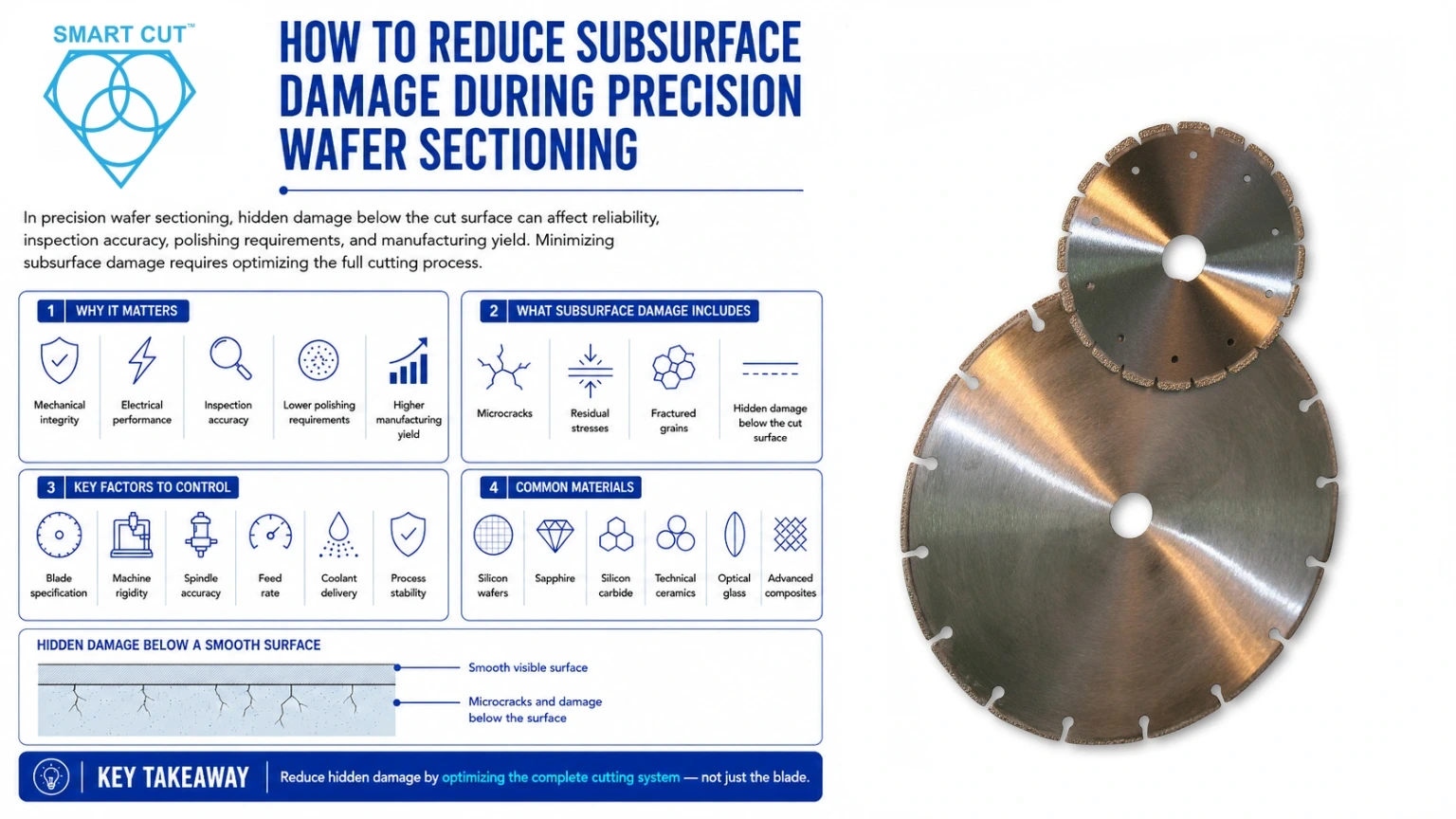
Table of Contents
Toggle
American Based Manufacturer

Established in 1990


Custom manufacturing


In precision wafer sectioning, what happens beneath the cut surface is often more important than what is visible to the naked eye.
A component may appear to have a smooth edge and acceptable dimensional accuracy, yet contain microscopic cracks, residual stresses, or fractured grains extending below the machined surface. These hidden defects, collectively referred to as subsurface damage, can compromise the mechanical integrity, electrical performance, and long-term reliability of the finished component.
For industries working with silicon wafers, sapphire substrates, silicon carbide, technical ceramics, advanced composites, optical glass, and metallographic specimens, subsurface damage is not simply a quality issue. It directly affects inspection accuracy, polishing requirements, manufacturing yield, and downstream analytical results.
As semiconductor devices become smaller and advanced materials continue to evolve, acceptable damage tolerances become increasingly narrow. Even microscopic flaws introduced during sectioning may influence failure analysis, microscopy, coating evaluation, dimensional verification, and precision assembly.
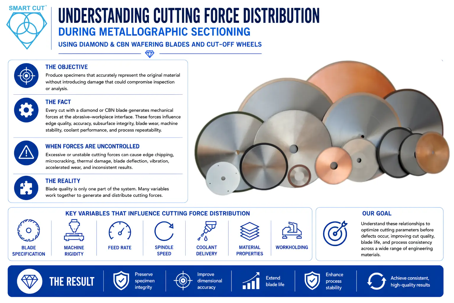
Reducing subsurface damage, therefore, requires far more than selecting a high-quality diamond blade. Blade specification, machine rigidity, spindle accuracy, feed rate, coolant delivery, and overall process stability all work together to determine how much damage is introduced beneath the cut surface.
This article explains how subsurface damage develops during precision wafer sectioning, why it matters, and which engineering practices help minimise hidden material damage while improving cutting consistency and sample integrity.
Why Subsurface Damage Matters
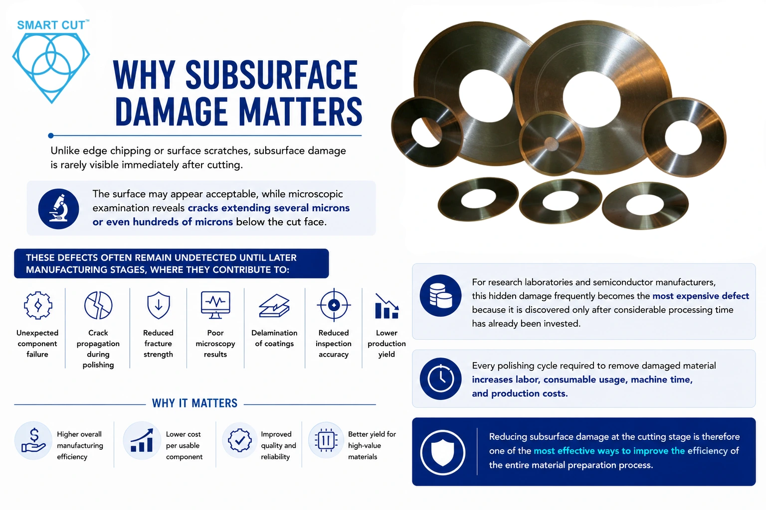
Unlike edge chipping or surface scratches, subsurface damage is rarely visible immediately after cutting.
The surface may appear acceptable, while microscopic examination reveals cracks extending several microns or even hundreds of microns below the cut face.
These defects often remain undetected until later manufacturing stages, where they contribute to:
- Unexpected component failure
- Crack propagation during polishing
- Reduced fracture strength
- Poor microscopy results
- Delamination of coatings
- Reduced inspection accuracy
- Lower production yield
For research laboratories and semiconductor manufacturers, this hidden damage frequently becomes the most expensive defect because it is discovered only after considerable processing time has already been invested.
Every polishing cycle required to remove damaged material increases labor, consumable usage, machine time, and production costs.
Reducing subsurface damage at the cutting stage is therefore one of the most effective ways to improve the efficiency of the entire material preparation process.
What Is Subsurface Damage?
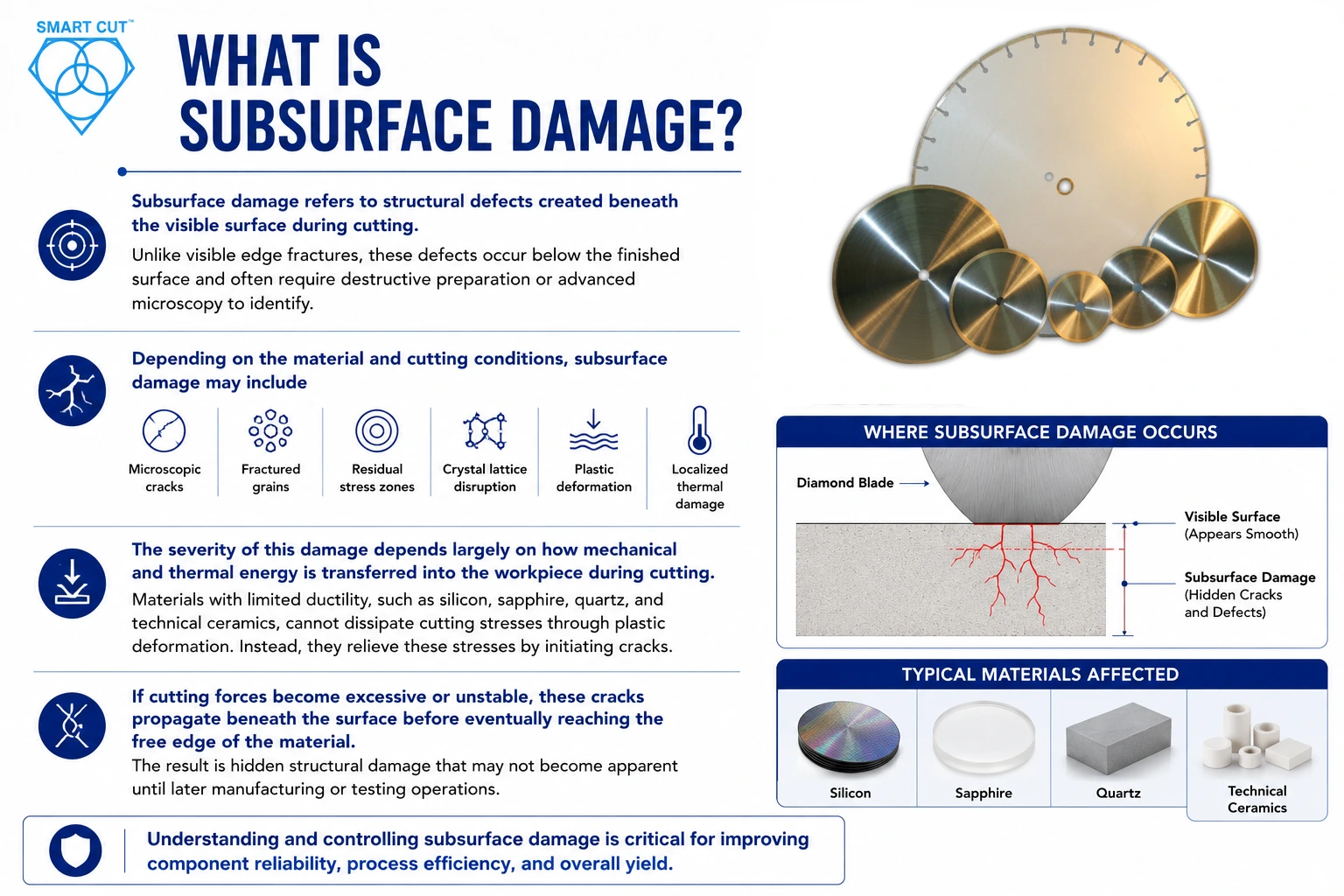
Subsurface damage refers to structural defects created beneath the visible surface during cutting.
Unlike visible edge fractures, these defects occur below the finished surface and often require destructive preparation or advanced microscopy to identify.
Depending on the material and cutting conditions, subsurface damage may include microscopic cracks, fractured grains, residual stress zones, crystal lattice disruption, plastic deformation, or localized thermal damage.
The severity of this damage depends largely on how mechanical and thermal energy is transferred into the workpiece during cutting.
Materials with limited ductility, such as silicon, sapphire, quartz, and technical ceramics, cannot dissipate cutting stresses through plastic deformation. Instead, they relieve these stresses by initiating cracks.
If cutting forces become excessive or unstable, these cracks propagate beneath the surface before eventually reaching the free edge of the material.
The result is hidden structural damage that may not become apparent until later manufacturing or testing operations.
Surface Damage vs. Subsurface Damage
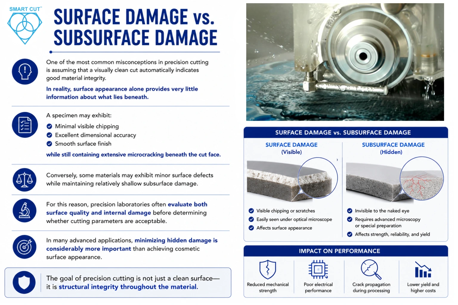
One of the most common misconceptions in precision cutting is assuming that a visually clean cut automatically indicates good material integrity.
In reality, surface appearance alone provides very little information about what lies beneath.
A specimen may exhibit:
- Minimal visible chipping
- Excellent dimensional accuracy
- Smooth surface finish
while still containing extensive microcracking beneath the cut face.
Conversely, some materials may exhibit minor surface defects while maintaining relatively shallow subsurface damage.
For this reason, precision laboratories often evaluate both surface quality and internal damage before determining whether cutting parameters are acceptable.
In many advanced applications, minimizing hidden damage is considerably more important than achieving cosmetic surface appearance.
Types of Subsurface Damage
Although the exact damage mechanism varies between materials, several forms occur repeatedly in precision wafer sectioning.
Microcracks
Microcracks are extremely small fractures that originate beneath the cut surface.
Initially, they may have little influence on part appearance, but under mechanical loading or thermal cycling, they often propagate into larger fractures.
Microcracks are particularly common when sectioning:
Silicon
Sapphire
Glass
Alumina ceramics
Median Cracks
Median cracks form beneath the cutting zone and extend downward into the material.
These cracks are typically generated by excessive localized cutting forces.
If not removed during polishing, they may significantly reduce mechanical strength.
Lateral Cracks
Lateral cracks propagate nearly parallel to the cut surface.
As they grow, they often intersect the free surface, resulting in:
- Edge chipping
- Surface breakout
- Material loss
These cracks are especially problematic during semiconductor sample preparation because they reduce edge integrity.
Grain Pull-Out
Polycrystalline materials such as alumina, zirconia, tungsten carbide, and many engineering ceramics may experience grain pull-out instead of continuous cracking.
Individual grains detach from the surrounding structure when cutting stresses exceed grain boundary strength.
This creates:
- Surface pits
- Increased roughness
- Reduced dimensional accuracy
- Additional polishing requirements
Residual Stress
Not all subsurface damage involves visible cracking.
Mechanical loading during cutting may introduce residual stresses that remain trapped within the material.
Although invisible, these stresses can later contribute to:
- Warping
- Crack initiation
- Coating failure
- Reduced component reliability
Residual stress is often evaluated in high-performance electronic, optical, and aerospace applications.
Materials Most Susceptible to Subsurface Damage
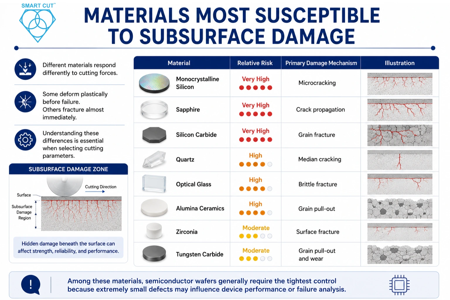
Different materials respond differently to cutting forces.
Some deform plastically before failure.
Others fracture almost immediately.
Understanding these differences is essential when selecting cutting parameters.
| Material | Relative Risk | Primary Damage Mechanism |
|---|---|---|
| Monocrystalline Silicon | Very High | Microcracking |
| Sapphire | Very High | Crack propagation |
| Silicon Carbide | Very High | Grain fracture |
| Quartz | High | Median cracking |
| Optical Glass | High | Brittle fracture |
| Alumina Ceramics | High | Grain pull-out |
| Zirconia | Moderate | Surface fracture |
| Tungsten Carbide | Moderate | Grain pull-out and wear |
Among these materials, semiconductor wafers generally require the tightest control because extremely small defects may influence device performance or failure analysis.
Why Brittle Materials Behave Differently
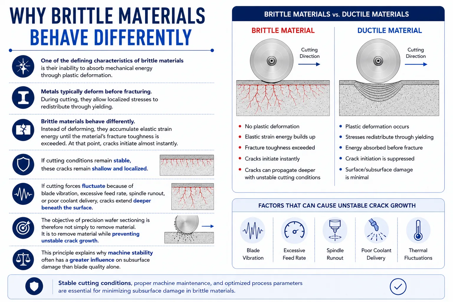
One of the defining characteristics of brittle materials is their inability to absorb mechanical energy through plastic deformation.
Metals typically deform before fracturing.
During cutting, they allow localized stresses to redistribute through yielding.
Brittle materials behave differently.
Instead of deforming, they accumulate elastic strain energy until the material’s fracture toughness is exceeded.
At that point, cracks initiate almost instantly.
If cutting conditions remain stable, these cracks remain shallow and localized.
If cutting forces fluctuate because of blade vibration, excessive feed rate, spindle runout, or poor coolant delivery, cracks extend deeper beneath the surface.
The objective of precision wafer sectioning is therefore not simply to remove material.
It is to remove material while preventing unstable crack growth.
This principle explains why machine stability often has a greater influence on subsurface damage than blade quality alone.
Why Subsurface Damage Is Frequently Overlooked
Many production facilities rely primarily on visual inspection after cutting.
If the cut appears acceptable, processing continues.
Unfortunately, this approach often fails to detect hidden structural defects.
Subsurface damage may only become apparent during:
Fine polishing
SEM preparation
Failure analysis
Mechanical testing
Thermal cycling
Device assembly
At that stage, correcting the damage becomes significantly more expensive than preventing it during the original cutting operation.
For precision laboratories, reducing subsurface damage is therefore one of the highest-return process improvements available.
How Cutting Parameters Influence Subsurface Damage
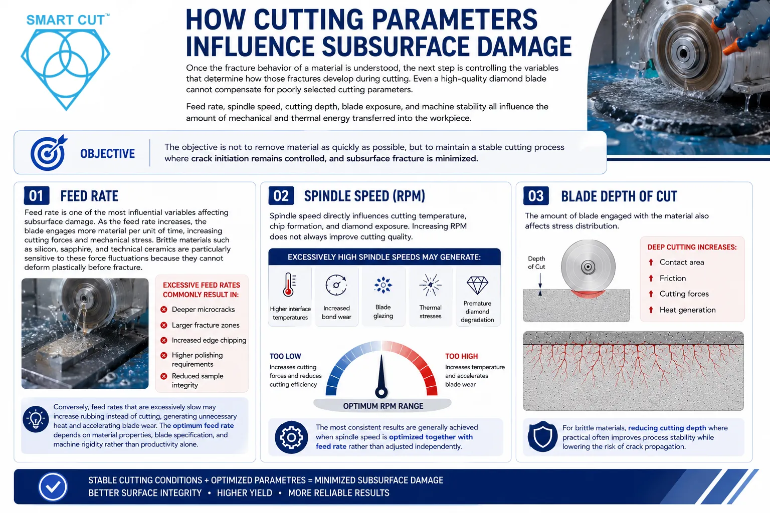
Once the fracture behavior of a material is understood, the next step is controlling the variables that determine how those fractures develop during cutting. Even a high-quality diamond blade cannot compensate for poorly selected cutting parameters. Feed rate, spindle speed, cutting depth, blade exposure, and machine stability all influence the amount of mechanical and thermal energy transferred into the workpiece.
The objective is not to remove material as quickly as possible, but to maintain a stable cutting process where crack initiation remains controlled, and subsurface fracture is minimized.
Feed Rate
Feed rate is one of the most influential variables affecting subsurface damage.
As the feed rate increases, the blade engages more material per unit of time, increasing cutting forces and mechanical stress. Brittle materials such as silicon, sapphire, and technical ceramics are particularly sensitive to these force fluctuations because they cannot deform plastically before fracture.
Excessive feed rates commonly result in:
- Deeper microcracks
- Larger fracture zones
- Increased edge chipping
- Higher polishing requirements
- Reduced sample integrity
Conversely, feed rates that are excessively slow may increase rubbing instead of cutting, generating unnecessary heat and accelerating blade wear. The optimum feed rate, therefore, depends on material properties, blade specification, and machine rigidity rather than productivity alone.
Spindle Speed (RPM)
Spindle speed directly influences cutting temperature, chip formation, and diamond exposure.
Increasing RPM does not always improve cutting quality.
Excessively high spindle speeds may generate:
- Higher interface temperatures
- Increased bond wear
- Blade glazing
- Thermal stresses
- Premature diamond degradation
Very low spindle speeds, however, may increase cutting forces and reduce cutting efficiency.
The most consistent results are generally achieved when spindle speed is optimized together with feed rate rather than adjusted independently.
Blade Depth of Cut
The amount of blade engaged with the material also affects stress distribution.
Deep cutting increases:
- Contact area
- Friction
- Cutting forces
- Heat generation
For brittle materials, reducing cutting depth where practical often improves process stability while lowering the risk of crack propagation.
Selecting the Right Diamond Blade
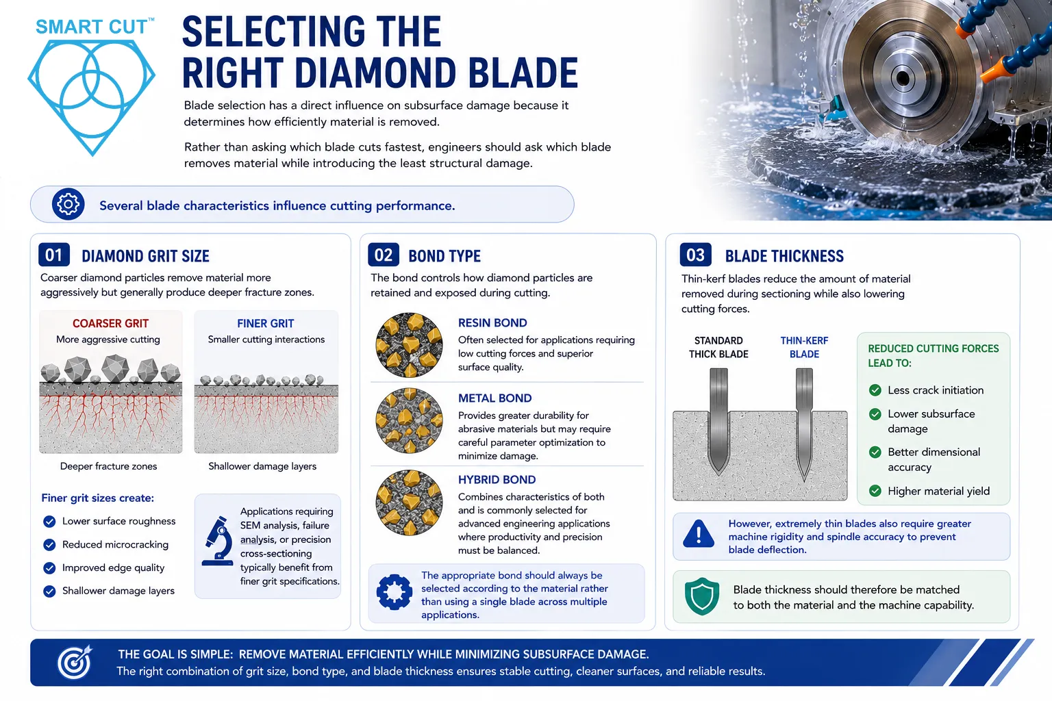
Blade selection has a direct influence on subsurface damage because it determines how efficiently material is removed.
Rather than asking which blade cuts fastest, engineers should ask which blade removes material while introducing the least structural damage.
Several blade characteristics influence cutting performance.
Diamond Grit Size
Coarser diamond particles remove material more aggressively but generally produce deeper fracture zones.
Finer grit sizes create smaller cutting interactions with the material, often resulting in:
Lower surface roughness
Reduced microcracking
Improved edge quality
Shallower damage layers
Applications requiring SEM analysis, failure analysis, or precision cross-sectioning typically benefit from finer grit specifications.
Bond Type
The bond controls how diamond particles are retained and exposed during cutting.
Resin bond blades are often selected for applications requiring low cutting forces and superior surface quality.
Metal bond blades generally provide greater durability for abrasive materials but may require careful parameter optimization to minimize damage.
Hybrid bond systems combine characteristics of both and are commonly selected for advanced engineering applications where productivity and precision must be balanced.
The appropriate bond should always be selected according to the material rather than using a single blade across multiple applications.
Blade Thickness
Thin-kerf blades reduce the amount of material removed during sectioning while also lowering cutting forces.
Reduced cutting forces frequently translate into:
- Less crack initiation
- Lower subsurface damage
- Better dimensional accuracy
- Higher material yield
However, extremely thin blades also require greater machine rigidity and spindle accuracy to prevent blade deflection.
Blade thickness should therefore be matched to both the material and the machine capability.
Why Coolant Is Critical
Coolant is often viewed simply as a means of reducing temperature.
In precision wafer sectioning, its role is considerably broader.
Proper coolant delivery:
Removes heat from the cutting interface
Reduces friction
Flushes abrasive debris
Prevents blade loading
Stabilizes cutting forces
Without effective coolant delivery, localized temperatures increase rapidly.
Elevated temperatures may contribute to:
- Residual stresses
- Surface burn
- Bond degradation
- Thermal cracking
- Reduced blade life
Equally important is coolant positioning.
Even high coolant flow rates provide limited benefit if coolant fails to reach the actual cutting interface.
Proper nozzle placement frequently has a greater influence on process stability than increasing pump capacity alone.
Machine Accuracy and Process Stability
The cutting system itself plays an equally important role in controlling subsurface damage.
Poor spindle accuracy introduces vibration that repeatedly changes cutting forces during blade rotation.
This unstable loading encourages crack propagation beneath the cut surface.
Critical machine characteristics include:
Spindle runout
Blade concentricity
Machine rigidity
Precision workholding
Stable feed mechanisms
Even small alignment errors can significantly increase damage when processing brittle engineering materials.
Optimizing blade selection without addressing machine accuracy often produces only limited improvements.
Inspecting Subsurface Damage
Because subsurface damage cannot usually be identified through visual inspection, specialized evaluation methods are often required.
The inspection technique depends on the application, material, and required accuracy.
Common methods include:
| Inspection Method | Typical Application |
|---|---|
| Optical Microscopy | Surface crack evaluation |
| SEM Analysis | High-resolution fracture analysis |
| Cross-Sectional Polishing | Damage depth measurement |
| Confocal Microscopy | Surface characterization |
| Acoustic Microscopy | Internal defect detection |
| Interferometry | Surface profile evaluation |
For semiconductor and failure-analysis applications, cross-sectional microscopy remains one of the most reliable methods for evaluating hidden fracture zones.
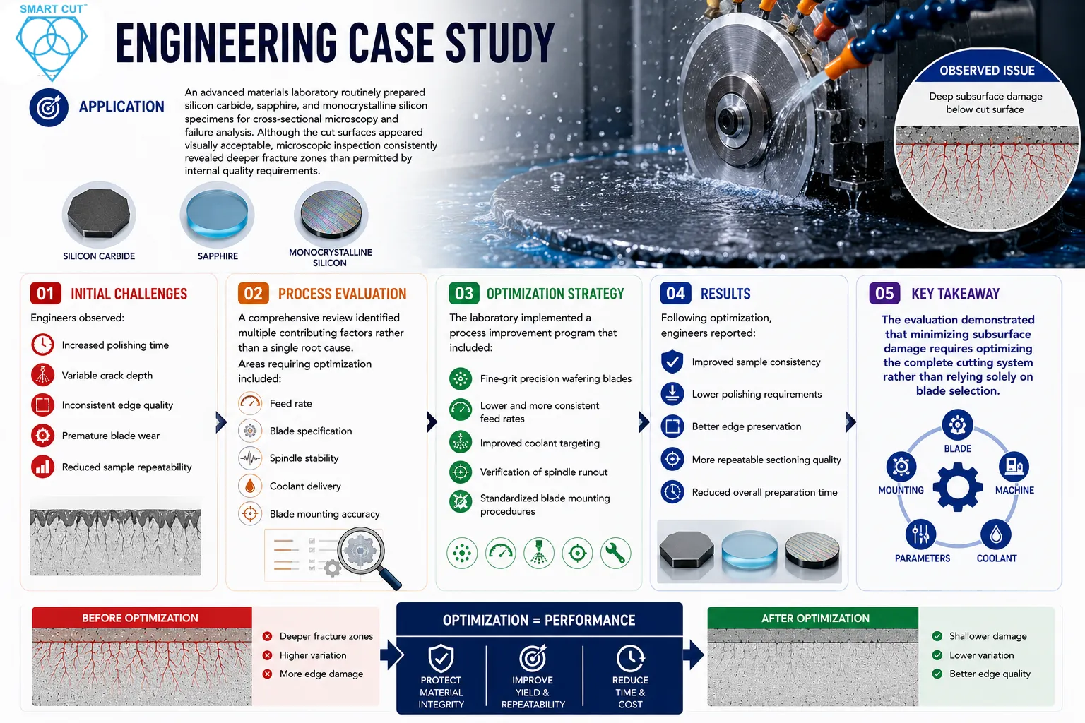
Engineering Case Study
Application
An advanced materials laboratory routinely prepared silicon carbide, sapphire, and monocrystalline silicon specimens for cross-sectional microscopy and failure analysis.
Although the cut surfaces appeared visually acceptable, microscopic inspection consistently revealed deeper fracture zones than permitted by internal quality requirements.
Initial Challenges
Engineers observed:
- Increased polishing time
- Variable crack depth
- Inconsistent edge quality
- Premature blade wear
- Reduced sample repeatability
Process Evaluation
A comprehensive review identified multiple contributing factors rather than a single root cause.
Areas requiring optimization included:
- Feed rate
- Blade specification
- Spindle stability
- Coolant delivery
- Blade mounting accuracy
Optimization Strategy
The laboratory implemented a process improvement program that included:
- Fine-grit precision wafering blades
- Lower and more consistent feed rates
- Improved coolant targeting
- Verification of spindle runout
- Standardized blade mounting procedures
Results
Following optimization, engineers reported:
- Improved sample consistency
- Lower polishing requirements
- Better edge preservation
- More repeatable sectioning quality
- Reduced overall preparation time
The evaluation demonstrated that minimizing subsurface damage requires optimizing the complete cutting system rather than relying solely on blade selection.
Note: Actual cutting parameters, microscopy images, and measured results can be incorporated where available to strengthen this case study.
Troubleshooting Guide
| Observation | Possible Cause | Recommended Action |
|---|---|---|
| Deep subsurface cracks | Feed rate too high | Reduce feed rate and stabilize cutting forces |
| Excessive edge chipping | Incorrect blade specification | Select finer grit or an appropriate bond |
| Thermal discoloration | Poor coolant delivery | Improve coolant targeting and flow |
| Variable cut quality | Blade runout | Verify spindle alignment and blade mounting |
| Rapid blade wear | Blade loading or overheating | Improve coolant filtration and optimize cutting parameters |
| Long polishing cycles | Excessive damage layer | Review blade selection and machine stability |
Recommended UKAM Solutions
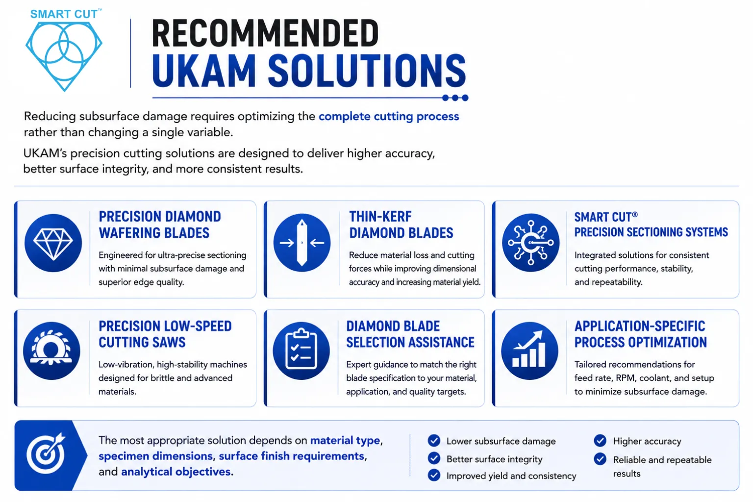
Reducing subsurface damage requires optimizing the complete cutting process rather than changing a single variable.
UKAM’s precision cutting solutions include:
- Precision Diamond Wafering Blades
- Thin-Kerf Diamond Blades
- SMART CUT® Precision Sectioning Systems
- Precision Low-Speed Cutting Saws
- Diamond Blade Selection Assistance
- Application-Specific Process Optimization
The most appropriate solution depends on material type, specimen dimensions, surface finish requirements, and analytical objectives.
Frequently Asked Questions
Subsurface damage consists of microscopic defects such as cracks, residual stresses, and fractured grains that develop beneath the visible cut surface during sectioning.
Most defects occur below the surface and usually require microscopy or cross-sectional analysis for evaluation.
Silicon, sapphire, silicon carbide, quartz, technical ceramics, and optical glass are among the most sensitive materials.
Yes. Blade grit size, bond type, kerf thickness, and diamond concentration all affect cutting forces and fracture behavior.
Higher feed rates generally increase cutting forces and may promote deeper crack formation.
Yes. Runout introduces vibration and unstable cutting forces that encourage crack propagation.
Coolant controls heat, reduces friction, removes debris, and helps stabilize the cutting process.
Lower cutting forces associated with thin-kerf blades often improve edge quality and reduce hidden damage when properly applied.
Common methods include optical microscopy, SEM analysis, cross-sectional polishing, confocal microscopy, and acoustic microscopy.
Polishing may remove shallow damage, but deeper fracture zones require significantly more material removal and increase preparation time.
The best results are achieved by optimizing blade selection, cutting parameters, coolant delivery, machine rigidity, and spindle accuracy together.
Reducing hidden damage improves sample integrity, inspection accuracy, polishing efficiency, manufacturing yield, and overall process reliability.
Conclusion
Subsurface damage remains one of the most critical—and often least visible—challenges in precision wafer sectioning. While edge quality and surface finish provide an immediate indication of cutting performance, they rarely reveal the hidden structural changes introduced beneath the cut surface.
For advanced materials such as silicon, sapphire, silicon carbide, quartz, technical ceramics, and optical glass, controlling subsurface damage requires a comprehensive approach that considers the interaction between blade specification, cutting parameters, coolant delivery, spindle accuracy, machine rigidity, and overall process stability.
Rather than focusing on a single process variable, manufacturers should optimize the complete cutting system to achieve consistent, low-damage sectioning.
By minimizing hidden fracture zones at the earliest stage of material preparation, laboratories and manufacturers can reduce polishing time, improve analytical accuracy, increase process repeatability, and maximize the value of every specimen prepared for inspection or downstream processing.
Trusted by Tens of Thousands of Manufacturers, Laboratories,
Research Institutions Worldwide Since 1990
American Based Manufacturer
Established in 1990
Custom manufacturing
RELATED ARTICLES

Brian is an experienced professional in the field of precision cutting tools, with over 27 years of experience in technical support. Over the years, he has helped engineers, manufacturers, researchers, and contractors find the right solutions for working with advanced and hard-to-cut materials. He’s passionate about bridging technical knowledge with real-world applications to improve efficiency and accuracy.
As an author, Brian Farberov writes extensively on diamond tool design, application engineering, return on investment strategies, and process optimization, combining technical depth with a strong understanding of customer needs and market dynamics.