








































How to Design a Repeatable Diamond Blade Test
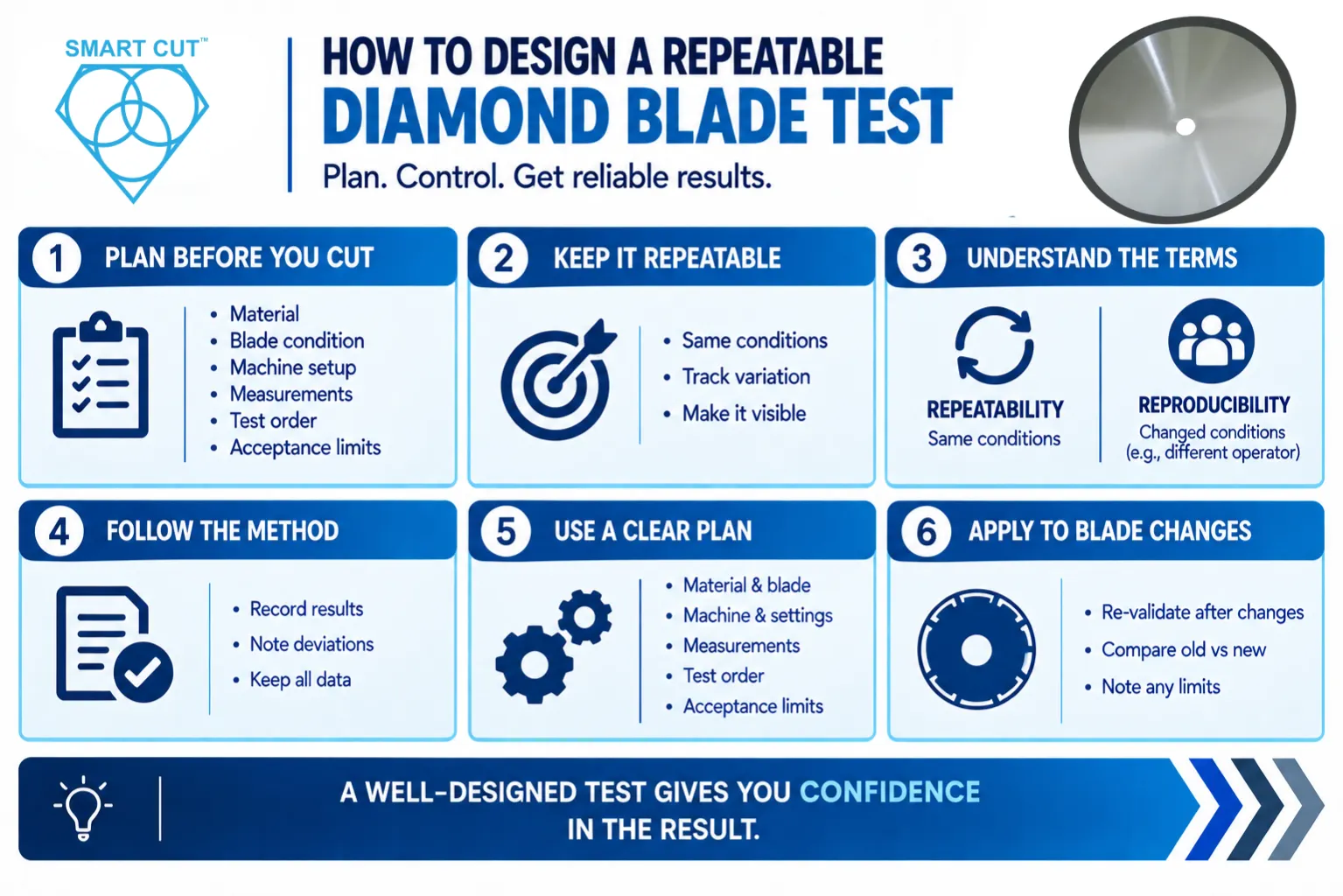
Table of Contents
ToggleA useful diamond blade test helps you decide whether a blade meets your cutting requirements and whether a measured difference is large enough to matter. To make that decision, you need a written plan for the material, blade condition, machine setup, measurements, test order, and acceptance limits before the first comparison cut.
Repeatability means obtaining closely agreeing results under the same defined conditions over a short period. It depends on both the test design and consistent execution. Some variation remains even in a well-controlled process. Your plan should make that variation visible so you can distinguish it from a meaningful performance difference.
Repeatability holds the operator, method, and measuring system fixed. Reproducibility checks agreement under specified changed conditions, such as different operators or measuring systems. State which conditions your validation covers.
This guide explains how to build that plan for precision diamond blade testing. The principles also apply to CBN blades when the blade, material, and operating conditions are appropriate for the application.
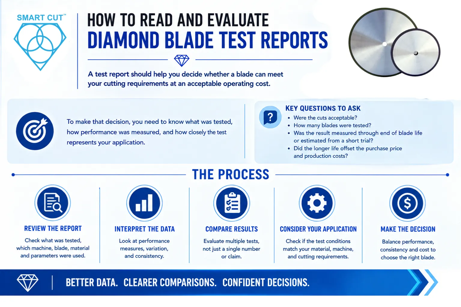
For the broader evaluation process and a comparison calculator, see UKAM’s guide to evaluating and comparing diamond blades.
Trusted by Tens of Thousands of Manufacturers, Laboratories Research Institutions Worldwide Since 1990

American Based Manufacturer

Established in 1990


Custom manufacturing


Start with the decision you need to make
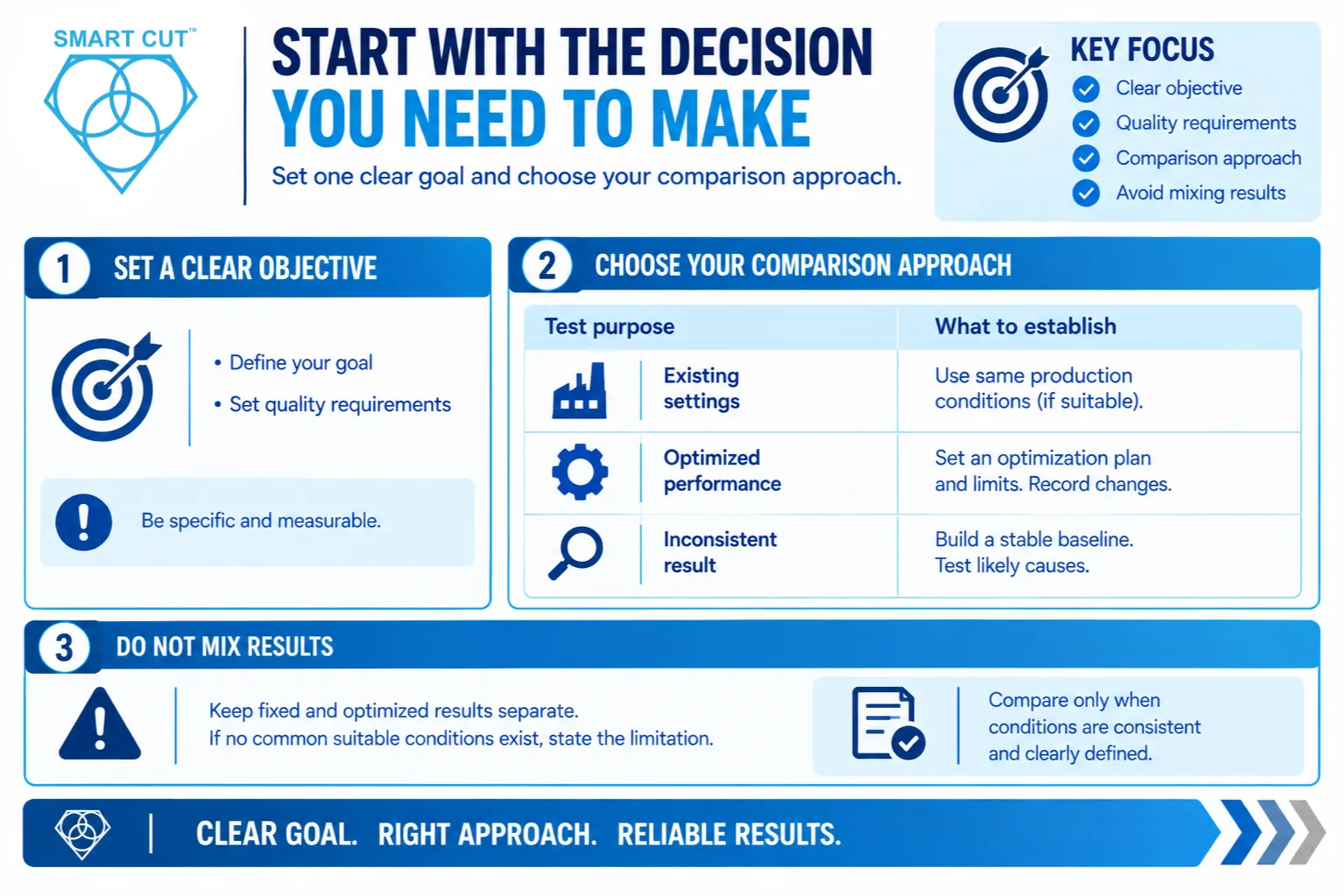
Write one clear objective. For example, you may need to reduce edge chipping while maintaining your current cycle time, or increase accepted parts per blade without exceeding a dimensional tolerance. Choose one primary outcome and identify the quality requirements that must also be met.
Define whether you are comparing blades at existing production settings or evaluating the best performance each blade can achieve. These approaches answer different questions.
| Test purpose | What the plan should establish |
|---|---|
| Compare at existing settings | Use the same documented production conditions where they are suitable and permitted for both blades. The result applies to that process. |
| Compare optimized performance | Define an optimization procedure and suitable limits for each blade. Record every adjustment. Confirm the selected settings with independent tests. |
| Investigate an inconsistent result | Establish a stable baseline. Test specific possible causes while preserving the original records and identifying each setup change. |
Do not combine results from fixed settings and optimized settings into one unlabeled comparison. A blade that performs poorly at one setting may behave differently within another suitable operating range. If no common suitable conditions exist, state that limitation before testing.
Define which conditions can change
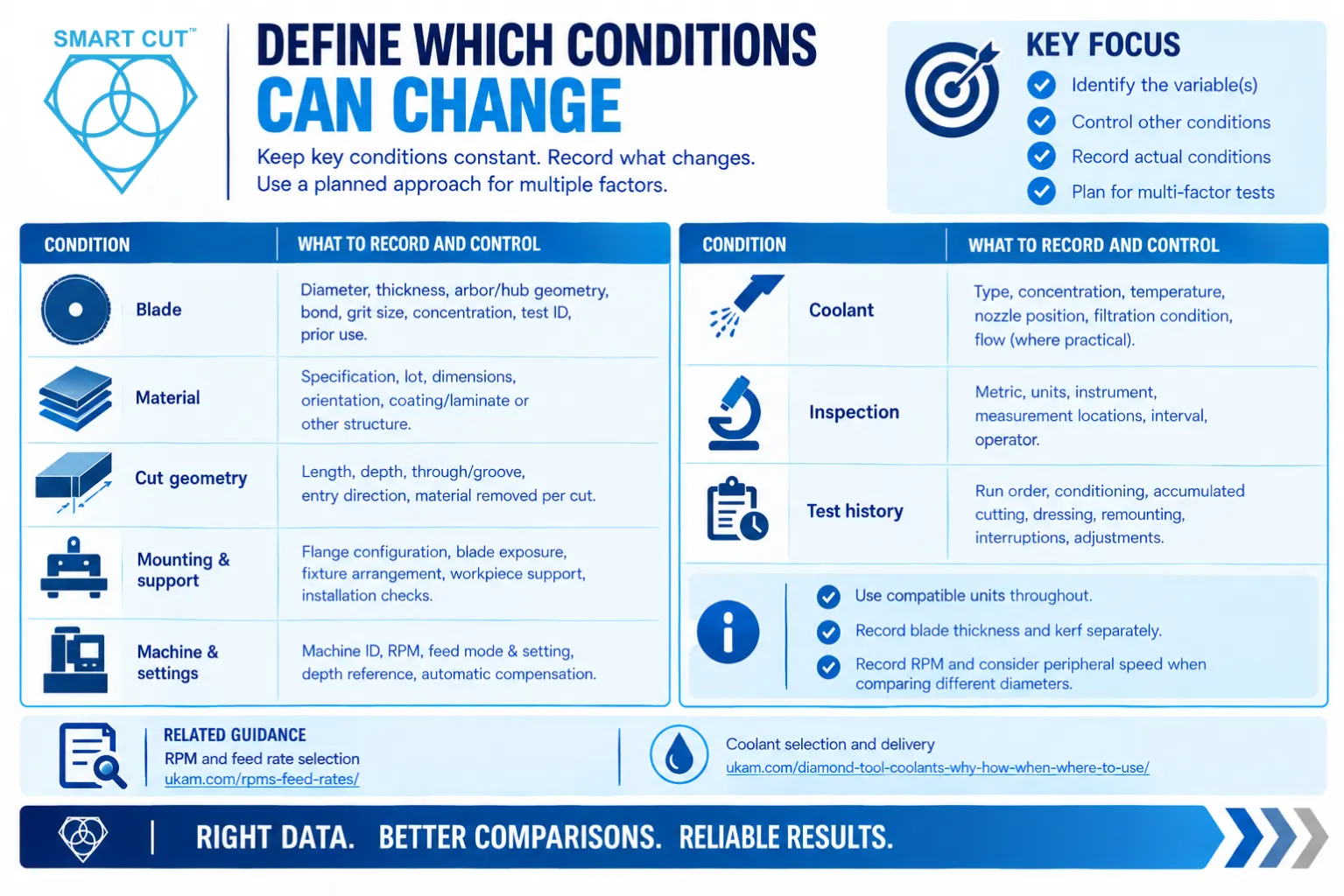
For a simple blade comparison, the blade option is the factor under study. Hold the other important conditions within documented limits, or account for their differences in the design. A recorded setpoint alone does not prove that the actual condition remained constant.
Changing one factor at a time can make a basic comparison easier to interpret. More advanced experiments can study several factors together, including interactions between blade specification, feed, and speed. Those experiments need a planned test matrix and an appropriate analysis.
| Condition | What to record and control |
|---|---|
| Blade | Diameter, thickness, arbor or hub geometry, bond, grit size, concentration designation, individual test identifier, and prior use. |
| Material | Material specification, lot, dimensions, orientation, and any coating, laminate, or other relevant structure. |
| Cut geometry | Cut length, depth, through-cut or groove, entry direction, and amount of material removed per cut. |
| Mounting and support | Flange configuration, blade exposure, fixture arrangement, workpiece support, and installation checks. |
| Machine and settings | Machine identifier, RPM, feed mode and setting, depth reference, and active automatic compensation. |
| Coolant | Type, concentration, temperature, nozzle position, filtration condition, and flow where practical. |
| Inspection | Metric, units, instrument, measurement locations, inspection interval, and operator. |
| Test history | Run order, conditioning, accumulated cutting, dressing, remounting, interruptions, and adjustments. |
Use compatible units throughout. Record blade thickness and measured kerf separately. Record spindle speed in RPM and, when comparing different blade diameters, consider the resulting peripheral speed. The same RPM does not produce the same peripheral speed at different diameters.
Related guidance is available on RPM and feed rate selection and coolant selection and delivery.
Establish a consistent starting condition
Verify the machine and mounting arrangement
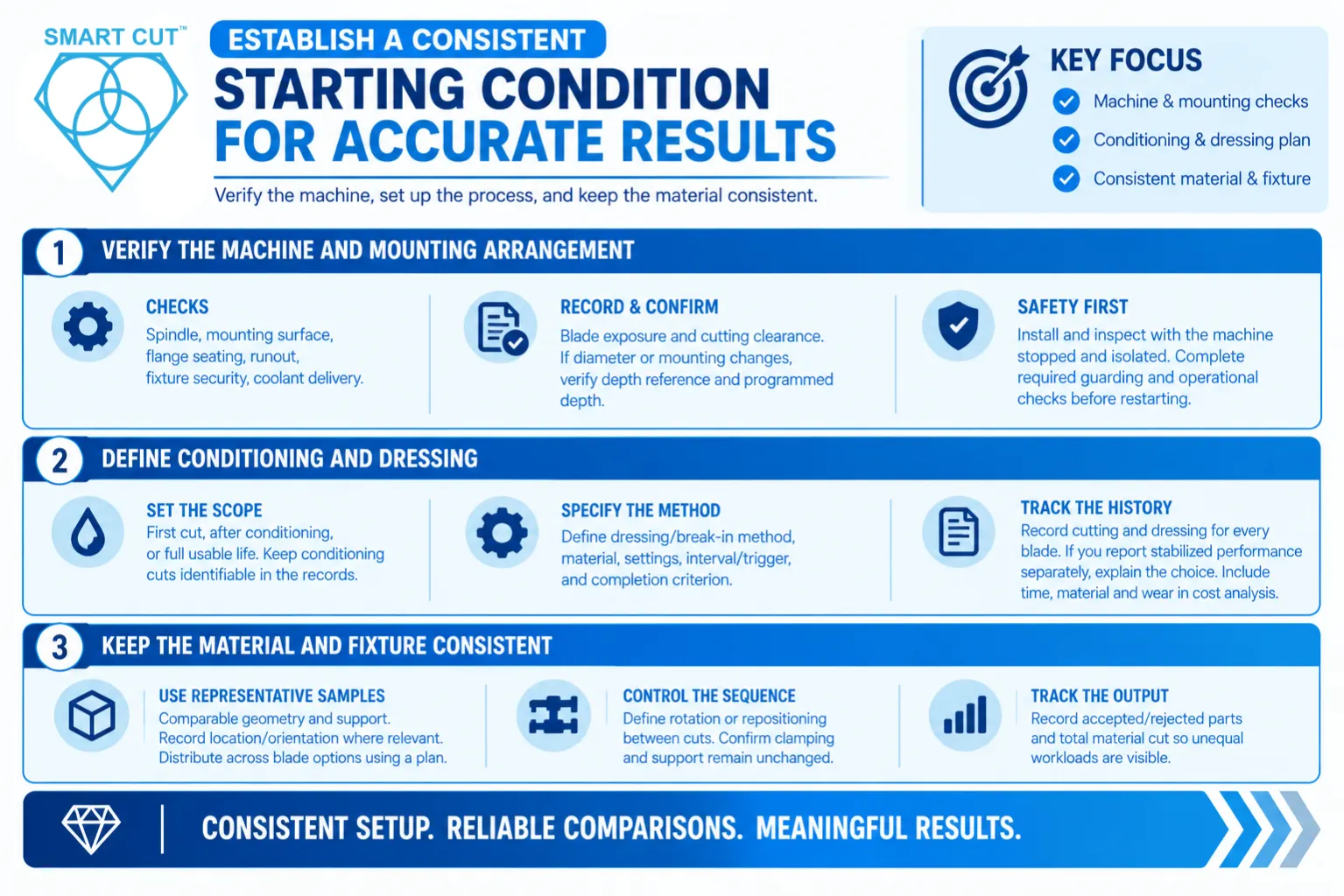
Define the checks that must pass before a test starts. These may include spindle condition, mounting surface cleanliness, flange seating, measured runout, fixture security, and coolant delivery. Use the machine and blade requirements for acceptance limits. Do not substitute a universal runout, tightening, or flange specification.
Record blade exposure and confirm sufficient cutting clearance. If blade diameter, exposure, or mounting geometry changes, verify the machine’s depth reference and programmed cutting depth. A change in blade installation can otherwise become an unrecorded change in the test.
Perform installation and inspection with the machine safely stopped and isolated as required by its instructions. Complete the prescribed guarding and operational checks before restarting.
Define conditioning and dressing
Specify whether the evaluation includes performance from the first cut, performance after a conditioning stage, or the complete usable life of the blade. Keep conditioning cuts identifiable in the records.
Where dressing or break-in is appropriate, define the method, material, settings, interval or trigger, and completion criterion. Follow guidance suitable for that blade construction. A dressing procedure appropriate for one bond or blade type may be unsuitable for another.
Record cutting and dressing history for every blade. If you evaluate production cost, account for the time, material, and blade wear consumed during preparation. A test of stabilized cutting performance can report conditioning separately, but should explain that choice.
Keep the material and fixture consistent
Use representative specimens with comparable geometry and support. Material from one lot can still vary. Where relevant, record specimen location or orientation and distribute specimens across blade options using a planned allocation.
If workpieces rotate or are repositioned between cuts, define that sequence. Confirm that clamping and support do not change as material is removed. Record accepted parts, rejected parts, and the amount of material cut so unequal workloads are visible.
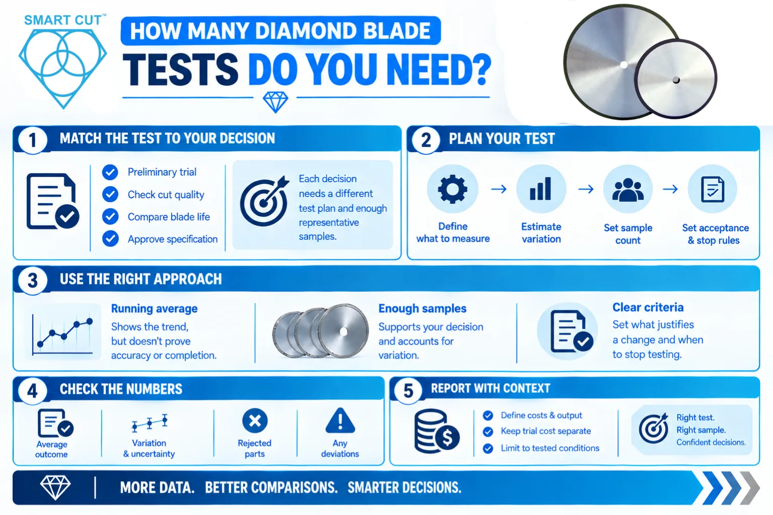
Plan independent repeats and test order
Distinguish repeated cuts with one blade from tests using separate physical blades. Repeated cuts show how an individual blade behaves during use. Separate blades are needed to estimate variation between blades. Repeated readings of one feature evaluate the inspection method.
For example, 100 cuts with one blade do not provide 100 independent observations of blade life. Preserve the individual blade identifier in the data and analyze repeated cuts as measurements associated with that blade.
There is no universal number of blades or cuts that makes every comparison dependable. Plan replication using the decision you need to make, preliminary variation, and the smallest worthwhile improvement. If you test only one blade of each option, describe the result as a preliminary comparison with limited evidence about consistency between blades.
Equal numbers of independent blade tests often simplify planning. Unequal numbers do not automatically invalidate a comparison, but you must document why they differ and use an analysis that handles the imbalance. Do not remove unfavorable results to make the counts match.
Use blocks to manage known differences
A block groups tests that share an important condition, such as a material lot or test session. If two material lots are necessary, test both blade options within each lot. Testing one option only on one lot makes the blade effect difficult to separate from the material effect.
This approach follows the principles described in NIST’s guidance on randomized block designs.
Choose the sequence before testing begins
Randomize the order within suitable blocks when practical. This reduces the risk that an unplanned time effect consistently favors one option. Randomization does not guarantee that every condition receives exactly the same influence in a small test.
Simple A/B/A/B alternation is not automatically sufficient. It always puts A before B within each pair. Consider order effects, machine warm-up, coolant condition, and practical blade-change requirements when choosing the schedule.
Define what one run means. It may be a fixed cutting interval or a complete blade-life test. Frequent changes between blades can introduce remounting variation. Where changes are necessary, use the same installation and verification procedure each time. Some wear tests require uninterrupted runs with order randomized between independent blades.
Use a reference blade with defined limits
A documented reference blade or reference specification can help identify changes in the test system. If you include periodic reference runs, define the workload, conditioning, expected range, and action to take when the result moves outside that range.
Track reference blade wear and accumulated use. A reference blade is not an unchanging standard. Its behavior may change because of wear, loading, dressing, or remounting, as well as machine or material changes. If a new reference blade is introduced, record the change and establish its baseline.
A stable reference result supports confidence in the conditions it checks. It does not prove that every other result is valid. An unexpected reference result should trigger investigation and a documented review of the affected tests.
Define every measurement before the first cut
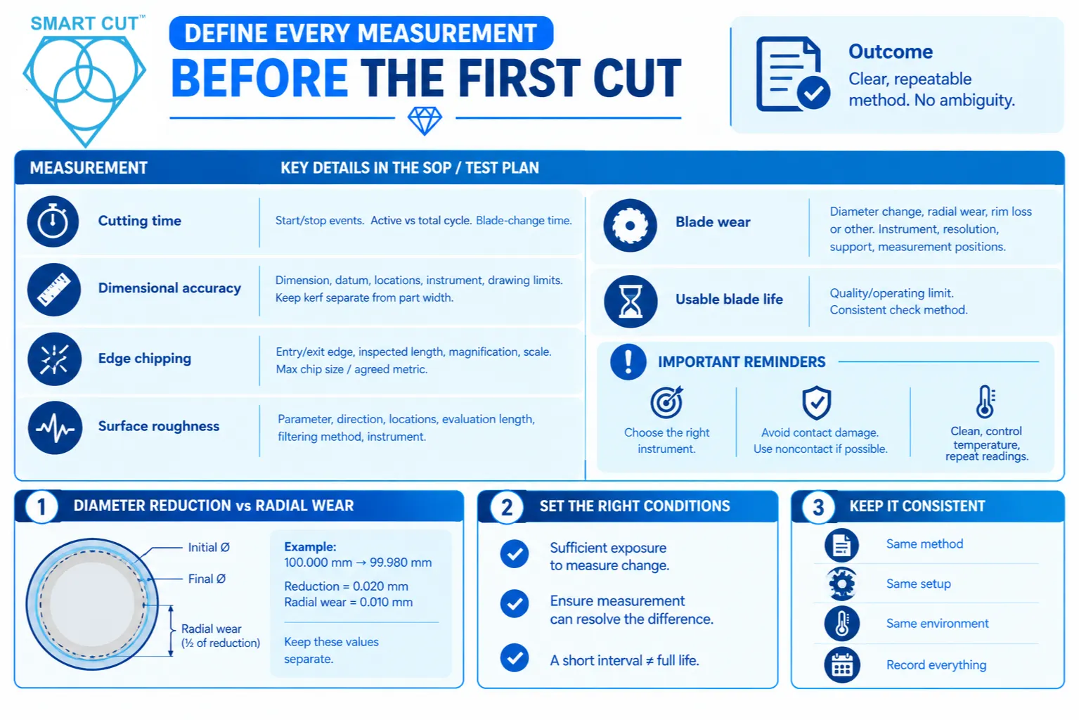
Write each measurement method so another trained person can follow it. State the metric, units, instrument, specimen preparation, location, timing, and calculation. Replace subjective descriptions such as good finish with a defined measurement or an agreed inspection standard.
| Outcome | A useful operational definition includes |
|---|---|
| Cutting time | The exact start and stop events. Separate active cutting time from total cycle time and blade-change time. |
| Dimensional accuracy | The dimension, datum, measurement locations, instrument, and drawing limits. Keep kerf width separate from finished part width. |
| Edge chipping | Entry or exit edge, inspected length, magnification, calibrated scale, and maximum chip size or other agreed metric. |
| Surface roughness | The specified parameter, measurement direction and locations, evaluation length, filtering method, and suitable instrument. |
| Blade wear | Diameter change, radial wear, rim height loss, or another defined quantity. State the instrument, resolution, support, and measurement positions. |
| Usable blade life | The predetermined quality or operating limit that ends useful service, and how consistently that limit is checked. |
Select an instrument suitable for the blade geometry and expected wear. A method that can measure a large diameter change may not resolve a small change in an ultra-thin blade. Contact force and support must not distort or damage the blade. Where practical, use a validated optical or other noncontact method when contact measurement is unsuitable.
For a diameter-based method, define measurement orientations, cleaning, temperature conditions, and repeat readings. Retain the readings before averaging them. If wear is uneven, report the individual observations and consider whether a single average diameter adequately describes the condition.
Keep diameter reduction and radial wear distinct
Diameter reduction equals initial diameter minus final diameter. For uniform radial wear, radial wear equals half the diameter reduction. These values must not be used interchangeably.
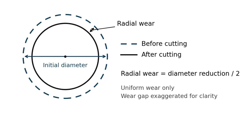
Example: a blade measured at 100.000 mm before cutting and 99.980 mm afterward has a diameter reduction of 0.020 mm. Under uniform wear, this corresponds to 0.010 mm of radial wear. These values illustrate the calculation only.
The inspection method must be capable of resolving the difference you intend to report. Choose sufficient cutting exposure to produce a measurable change without exceeding quality or operating limits. A short wear interval alone does not establish full blade life.
Check the inspection method separately
Repeatability and accuracy are different. An instrument can produce closely agreeing readings while carrying a consistent offset. Check calibration status and suitability for the measurement, as well as repeat readings.
To investigate inspection repeatability, measure the same stable feature several times without further cutting between readings. Include repositioning if repositioning is part of the actual method. For operator-related variation, have trained operators measure the same features using the same procedure.
Repeated cutting trials evaluate combined variation from the material, blade, machine, setup, and inspection. They do not isolate the measurement system by themselves.
For a formal assessment of these measurement effects, see NIST’s guidance on gauge repeatability and reproducibility studies.
Set acceptance limits and stopping rules
Before testing, specify the quality limits that must be met and the change in performance that would justify a decision. A longer blade life is not useful if the parts fail the required dimensions or edge-quality limits.
Define when to stop for blade damage, abnormal vibration, loss of coolant, unacceptable cut quality, or another relevant condition. Use the applicable machine and blade instructions for operating limits. Predetermine inspection intervals so one blade is not allowed to continue longer simply because it is checked less often.
Decide how to treat a test stopped for an unrelated event. If a machine problem ends a run before the blade reaches its life limit, record it as an interrupted or incomplete test. The observed cuts establish only the service completed before interruption. Do not report them as the blade’s full life.
Preserve rejected parts and abnormal results in the records. Exclude a result from a particular analysis only for a documented reason consistent with the test plan. Report exclusions and retain the underlying data.
Use a pilot to check the plan
Run a small pilot with representative material before committing the full test quantity. Exercise the intended preparation, cutting, inspection, logging, and stopping procedure. Confirm that the measurements are practical and that important settings can be held within the planned limits.
Use the pilot to estimate variation and refine replication. A small pilot gives preliminary information and may miss uncommon problems. It cannot guarantee the reliability of the full test.
Record any changes made after the pilot and freeze the revised protocol before the main comparison. Keep pilot data identified. If the protocol changes, do not silently pool earlier and later results. Pilot observations can still be reported transparently with their purpose and limitations.
Example of a planned blade comparison
The following example illustrates a fixed-setting screening test for precision cutting. All dimensions, limits, quantities, and identifiers are illustrative. They are not UKAM test results, operating recommendations, or a universal minimum sample size.
| Planning decision | Illustrative plan |
|---|---|
| Objective | Compare accepted parts during a fixed cutting interval. All parts must also meet the stated width and chipping limits. |
| Screening target | At least two additional accepted parts per 20-cut run, on average, with no increase in average cycle time. This illustrative target needs confirmation and is not a statistical decision rule. |
| Material and part | One material lot of ceramic coupons with matched geometry and orientation. Target finished width: 5.00 mm ±0.02 mm. |
| Quality limit | Maximum exit-edge chip size: 0.05 mm, measured perpendicular to the nominal edge over the full specified cut edge. |
| Blade allocation | Three separate blades of option A and three of option B. Give each physical blade its own internal test identifier. |
| Run definition | One new blade completes up to 20 measured cuts after the documented conditioning procedure, unless a stop criterion is reached. |
| Settings | Use the approved common RPM, feed mode, feed setting, depth, coolant conditions, and mounting arrangement. Enter the actual values before starting. |
| Inspection | Measure width and maximum exit-edge chip size on every part. Record accepted and rejected parts, cycle time, and interruptions. |
| Wear | Measure each blade before and after the measured interval using the validated method. Record whether the wear difference is resolvable. |
| Interpretation | Compare outcomes by physical blade and session. Confirm a promising result with enough independent testing for the required decision. |
An example schedule uses three sessions as blocks. Each session includes both blade options. Allocate comparable specimens to the runs and determine the sequence before beginning. The order below represents one possible outcome of randomizing within each session.
| Session | First run | Second run |
|---|---|---|
| 1 | B1 | A1 |
| 2 | A2 | B2 |
| 3 | B3 | A3 |
Each identifier represents a different physical blade. The schedule provides six independent blade runs and up to 120 measured cuts. The cuts within each blade remain associated with that blade. Conditioning cuts are recorded separately.
If a run ends early, retain the actual number of cuts, the reason for stopping, and the accepted-part count. Do not treat unequal exposure as equal. A fixed-interval test can compare performance over that interval, but it does not establish total blade life or universal cost per part.
Decide what the results support
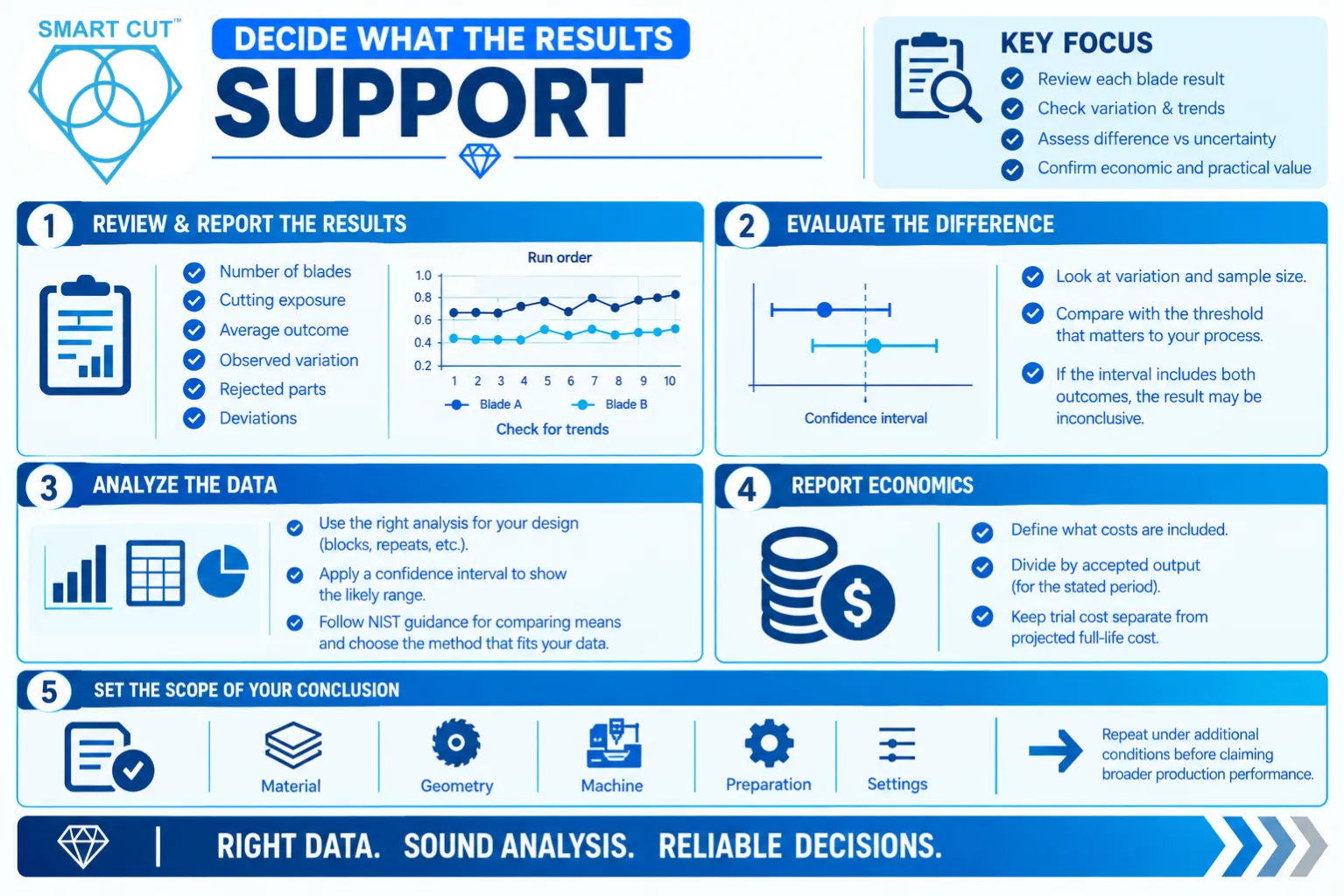
Review the individual blade results before combining them. Report the number of physical blades, cutting exposure, average outcome, observed variation, rejected parts, and deviations. Plot results in run order where useful to check for trends.
Closely grouped observations support repeatability under the tested conditions. They do not automatically establish accuracy or prove that a small difference between options is real. Evaluate the difference against its uncertainty and the improvement that matters to your process.
Use an analysis that matches the design, including blocks and repeated measurements where applicable. A confidence interval can help show the plausible range of the difference. If the interval includes both an unhelpful result and a worthwhile improvement, the test may be inconclusive. More independent testing or a better-controlled method may be needed.
The role of variation, sample size, and comparison thresholds is discussed in NIST’s guidance on comparing two means. Select the specific analysis to suit your data and design.
When reporting economics, define the costs included and divide by accepted output for the stated period. Keep a measured trial cost separate from a projected full-life cost. Do not extend short-interval wear into a full-life claim without explaining and validating the assumptions.
Limit the conclusion to the tested material, geometry, machine, preparation, and settings. Repeat the comparison under additional relevant conditions before claiming broader production performance.
Preserve the method for future testing
Transfer the validated plan into a controlled procedure. Include the revision, responsible person, training requirements, setup limits, conditioning method, inspection instructions, test order, data fields, and acceptance rules.
Keep the raw readings, part images with scale references, blade histories, and deviations with the test record. Review the procedure when the material, blade geometry, fixture, machine, coolant, or inspection method changes. Periodic verification is needed to maintain confidence in repeatability.
Frequently Asked Questions
Yes, as a preliminary screen under documented conditions. It provides limited information about variation between blades. Use separate physical blades when your decision depends on consistent performance across production quantities.
Use common settings when you are evaluating performance in an existing process and those settings are suitable for both blades. Use a separate, documented optimization plan when you want to compare each blade’s achievable performance.
Usually the run structure should follow the test objective. Changing after every cut can introduce remounting variation and may interrupt the wear process you want to study. Choose suitable run lengths and manage time effects through the planned blocks and sequence.
The acceptable variation depends on your quality limits and the performance difference you need to detect. Establish the decision threshold before testing. There is no single repeatability percentage that proves every blade comparison is adequate.
Review its wear, conditioning, accumulated use, and mounting history alongside machine, material, and coolant records. Investigate the affected interval and document whether results can be interpreted or need confirmation.
It supports confidence under the tested conditions. Production may include other operators, sessions, material lots, and machines. Extend the validation to the conditions that matter to your process before making a broader claim.
Get help planning your diamond blade test
UKAM Industrial Superhard Tools manufactures precision diamond and CBN blades and cutting equipment. We can help you review the blade specification and the conditions that should be documented for a useful application test.
When you request assistance, provide your material and dimensions, machine information, blade specification, mounting and exposure details, RPM and feed settings, coolant setup, and required cut quality. Include existing test records and clear photographs when available.
Request applications engineering assistance to discuss your test objective and the information needed to evaluate the results.
Trusted by Tens of Thousands of Manufacturers, Laboratories,
Research Institutions Worldwide Since 1990
American Based Manufacturer
Established in 1990
Custom manufacturing
RELATED ARTICLES




Brian is an experienced professional in the field of precision cutting tools, with over 27 years of experience in technical support. Over the years, he has helped engineers, manufacturers, researchers, and contractors find the right solutions for working with advanced and hard-to-cut materials. He’s passionate about bridging technical knowledge with real-world applications to improve efficiency and accuracy.
As an author, Brian Farberov writes extensively on diamond tool design, application engineering, return on investment strategies, and process optimization, combining technical depth with a strong understanding of customer needs and market dynamics.