








































Diamond Wire Cutting for Silicon, Sapphire & Ceramics

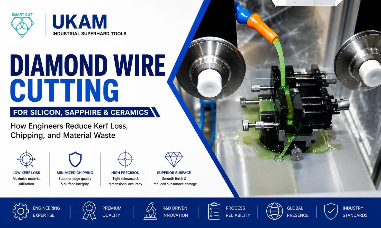
Table of Contents
Toggle
American Based Manufacturer

Established in 1990


Custom manufacturing


How Engineers Reduce Kerf Loss, Chipping, and Material Waste
When cutting silicon, sapphire, quartz, advanced ceramics, glass, SiC, or other hard and brittle materials, the cutting tool does more than separate one piece from another.
It determines how much material is lost, how much damage is introduced into the cut surface, how much secondary processing is required, and how consistently the finished parts can meet dimensional requirements.
This becomes particularly important when the workpiece itself is expensive.
A small increase in kerf width can translate into significant material loss across hundreds or thousands of cuts. A small increase in subsurface damage can create additional polishing or grinding requirements. Excessive chipping can reduce yield. And an incorrectly selected diamond wire can increase cutting time, wire consumption, and total process cost.
That is why the engineering question is not simply:
“Can diamond wire cut this material?”
A better question is:
“How should the diamond wire, cutting parameters, machine, and cooling system be matched to minimize material loss while maintaining cut quality, productivity, and process stability?”
UKAM’s current SMART CUT® diamond-wire range is intended for precision cutting of artificial crystals, ceramics, quartz glass, monocrystalline and polycrystalline silicon, sapphire, specialty metals, and other hard or brittle materials. The company describes the process as producing low kerf loss, reduced subsurface damage, dimensional accuracy, and smooth surfaces, while eliminating the slurry-recycling and disposal issues associated with older abrasive slurry methods.
This article examines the engineering variables that determine whether a diamond-wire process actually delivers those benefits.
Why Cutting Hard and Brittle Materials Is Difficult
Silicon, sapphire, ceramics, quartz, glass, SiC, and optical crystals do not behave like ordinary ductile metals.
They can be:
Extremely hard · Brittle · Abrasive · Sensitive to localized stress · Sensitive to vibration · Sensitive to thermal gradients · Expensive enough that material loss directly affects manufacturing economics
When a conventional cutting tool removes material, the material may deform plastically before separating.
In brittle materials, excessive stress can instead initiate or propagate cracks.
The result may be:
Edge chipping · Microcracking · Subsurface damage · Surface roughness · Dimensional variation · Warping · Material breakage
The cutting process therefore has to balance material removal rate against material integrity.
Engineering Question
What happens when the cutting process becomes faster but the material damage increases faster than productivity improves?
The answer is often a lower overall yield.
That is why optimizing diamond-wire cutting requires more than maximizing cutting speed.
What Is Diamond Wire Cutting?
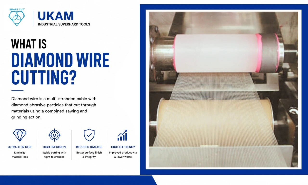
Diamond wire consists of a wire core carrying diamond abrasive particles that perform the cutting action.
The wire moves through or across the workpiece while exposed diamond particles abrade the material.
UKAM describes diamond wire as a multi-stranded cable impregnated or coated with diamond grains, with the cutting action combining sawing and grinding, as detailed in the diamond wire advantages and application reference article.
Unlike a conventional saw blade, the cutting element can be extremely narrow.
This provides one of the major advantages of diamond wire:
The possibility of achieving a very small kerf while maintaining controlled abrasive cutting.
UKAM lists diamond-wire configurations with very low kerf loss, including approximately 0.12–0.42 mm for its broader diamond-wire offering. Its current product information also identifies fine-wire configurations for semiconductor wafers, sapphire, and optics.
Why Kerf Loss Matters
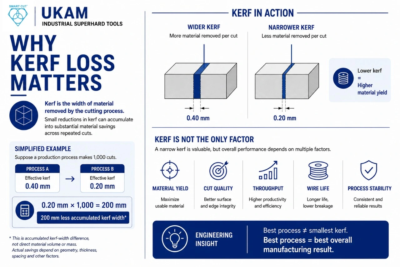
Kerf is the width of material removed by the cutting process.
If a blade has a 1 mm kerf, approximately 1 mm of material is consumed along the cut path.
With expensive materials, that loss can become significant.
Consider a simplified illustrative example.
Suppose a production process makes:
1,000 cuts — and each cut has an effective kerf of: Process A: 0.40 mm · Process B: 0.20 mm
The difference is: 0.20 mm × 1,000 = 200 mm
That does not by itself tell us the exact mass or economic loss because the workpiece geometry and material volume must also be considered.
But it illustrates the principle:
Small reductions in kerf can accumulate into substantial material savings across repeated cuts.
For high-value silicon, sapphire, crystals, or specialty ceramics, that can become a major production consideration, as covered in UKAM’s semiconductor wafer manufacturing process guide.
Illustrative Material-Yield Example
The following example is illustrative only and does not represent a UKAM production guarantee.
Imagine a cylindrical silicon workpiece that requires 100 wafer cuts. Two cutting processes are being evaluated:
|
Metric |
Process A |
Process B |
|---|---|---|
|
Effective kerf |
0.30 mm |
0.18 mm |
|
Number of cuts |
100 |
100 |
|
Theoretical accumulated kerf width |
30 mm |
18 mm |
|
Difference |
— |
12 mm |
The 12 mm difference is not necessarily the final material-saving figure because wafer thickness, cut spacing, edge exclusion, kerf variation, and other factors must be included.
However, it shows why engineers should treat kerf as a yield variable, not merely a cutting-tool specification, as reinforced in how silicon wafers are made.
Kerf Is Not the Only Measure of Cutting Efficiency
A narrow kerf is valuable.
But an extremely narrow kerf is not automatically the best process if it creates:
Excessive cutting time · Frequent wire breakage · Poor surface quality · High wire consumption · Excessive subsurface damage · Poor dimensional control
The better engineering objective is:
Material yield + cut quality + throughput + wire life + process stability
rather than:
Minimum kerf at any cost
Engineering Insight
The best diamond-wire process is not necessarily the one with the smallest kerf. It is the one that produces the best overall manufacturing result — a principle also explored in UKAM’s silicon fabrication guide.
What Determines Diamond-Wire Performance?
UKAM identifies several variables that affect diamond-wire performance, including: cutting speed, pressure, material preparation, weld strength, cutting fluid, blade/wire diameter, and material being cut — the same framework used in UKAM’s guide to choosing the correct diamond bond type.
This is important because diamond wire should not be evaluated as an isolated consumable. Its performance is the result of an interaction between the wire and the complete cutting system.
Wire Diameter: Small Does Not Always Mean Better
Wire diameter has a direct relationship with potential kerf.
A smaller wire can reduce material removed by the cut.
But reducing diameter can also affect: Tensile strength · Wire stiffness · Breakage resistance · Cutting stability · Required machine settings · Handling · Tension requirements
UKAM’s current information describes fine-wire configurations approximately in the 75–180 µm range for semiconductor wafers, sapphire, and optics, medium wire around 240–340 µm for solar wafers, glass, and ceramics, and larger wire approximately 340–420 µm for applications such as stone, composites, and silicon ingots.
These ranges demonstrate an important engineering principle:
Wire diameter should be selected according to the application, not simply minimized.
Engineering Question: How Thin Should the Wire Be?
Suppose an engineer is deciding between two wire diameters.
Wire A — Lower diameter · Potentially lower kerf · Higher sensitivity to tension and handling
Wire B — Larger diameter · Higher kerf · Potentially greater mechanical robustness
Which is better? The answer depends on: Material value · Cut dimensions · Required accuracy · Machine capability · Production volume · Wire-break risk · Required throughput
If Wire A reduces material loss but causes frequent breakage, the theoretical material saving may disappear in downtime and scrap — a trade-off quantified further in UKAM’s practical guide to semiconductor wafer dicing.
Diamond Grit Size Changes the Cutting Behavior
Diamond grit is another major variable.
UKAM’s current diamond-wire information identifies grit sizes from approximately 5–50 µm across its wire configurations.
In general, grit selection influences: Cutting aggressiveness · Surface condition · Kerf characteristics · Material-removal behavior · Cutting forces · Potential damage
A coarser abrasive can provide more aggressive cutting in suitable applications.
A finer abrasive can support more controlled cutting and surface quality in appropriate applications.
But the correct choice depends on the material and process.
Engineering Question
Should the finest diamond grit always be used when cutting sapphire or silicon?
Not automatically.
A finer abrasive may support a particular surface-quality objective, but if the cutting action becomes inefficient, cycle time and process economics may suffer, as illustrated in UKAM’s precision ultra-thin diamond blade guide.
Diamond Wire Bond: Electroplated vs. Resin Bond
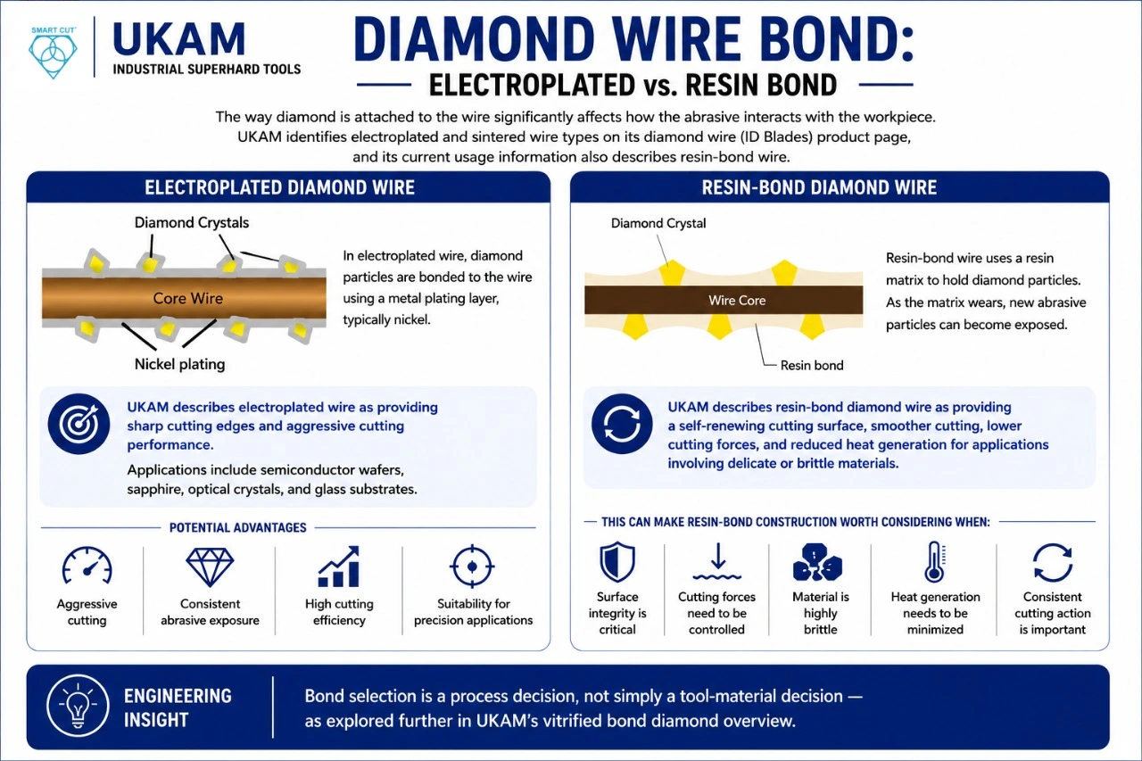
The way diamond is attached to the wire significantly affects how the abrasive interacts with the workpiece.
UKAM identifies electroplated and sintered wire types on its diamond wire (ID Blades) product page, and its current usage information also describes resin-bond wire.
Electroplated Diamond Wire
In electroplated wire, diamond particles are bonded to the wire using a metal plating layer, typically nickel.
UKAM describes electroplated wire as providing sharp cutting edges and aggressive cutting performance, with applications including semiconductor wafers, sapphire, optical crystals, and glass substrates — the same construction covered in UKAM’s electroplated diamond edge grinding wheel guide.
Potential advantages include: Aggressive cutting · Consistent abrasive exposure · High cutting efficiency · Suitability for precision applications
Resin-Bond Diamond Wire
Resin-bond wire uses a resin matrix to hold diamond particles.
As the matrix wears, new abrasive particles can become exposed.
UKAM describes resin-bond diamond wire as providing a self-renewing cutting surface, smoother cutting, lower cutting forces, and reduced heat generation for applications involving delicate or brittle materials.
This can make resin-bond construction worth considering when: Surface integrity is critical · Cutting forces need to be controlled · Material is highly brittle · Heat generation needs to be minimized · Consistent cutting action is important
Engineering Insight
Bond selection is a process decision, not simply a tool-material decision — as explored further in UKAM’s vitrified bond diamond overview.
Continuous Diamond Wire vs. Segmented Wire
Diamond wire can also differ in how the abrasive is distributed.
UKAM’s current information describes:
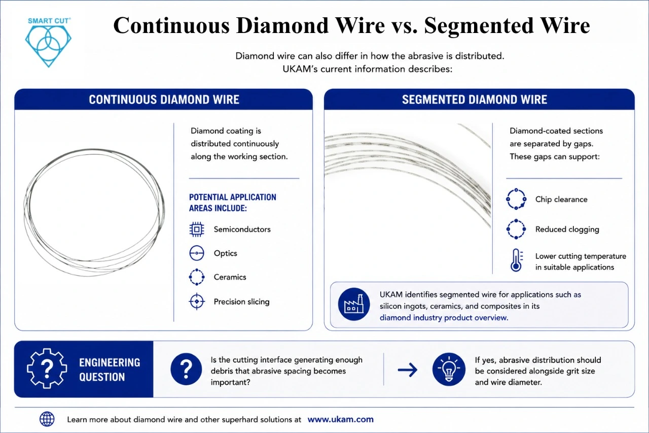
Continuous Diamond Wire
Diamond coating is distributed continuously along the working section. Potential application areas include: Semiconductors · Optics · Ceramics · Precision slicing
Segmented Diamond Wire
Diamond-coated sections are separated by gaps. These gaps can support: Chip clearance · Reduced clogging · Lower cutting temperature in suitable applications
UKAM identifies segmented wire for applications such as silicon ingots, ceramics, and composites in its diamond industry product overview.
Engineering Question
Is the cutting interface generating enough debris that abrasive spacing becomes important? If yes, abrasive distribution should be considered alongside grit size and wire diameter.
Multi-Layer and Spiral-Coated Diamond Wire
UKAM also describes multi-layer or spiral-coated diamond wire, intended to balance cutting speed, surface finish, and tool life, and identifies applications including photovoltaics, ceramics, and specialty glass — the same layered-exposure principle used in the 115DE SMART CUT diamond core drill series.
The advantage of considering multiple abrasive layers is that tool performance can be designed around longer cutting life rather than relying on a single exposed abrasive layer.
This becomes particularly relevant when production volume is high.
Spool-Based vs. Closed-Loop Diamond Wire
Diamond wire is used in different machine configurations.
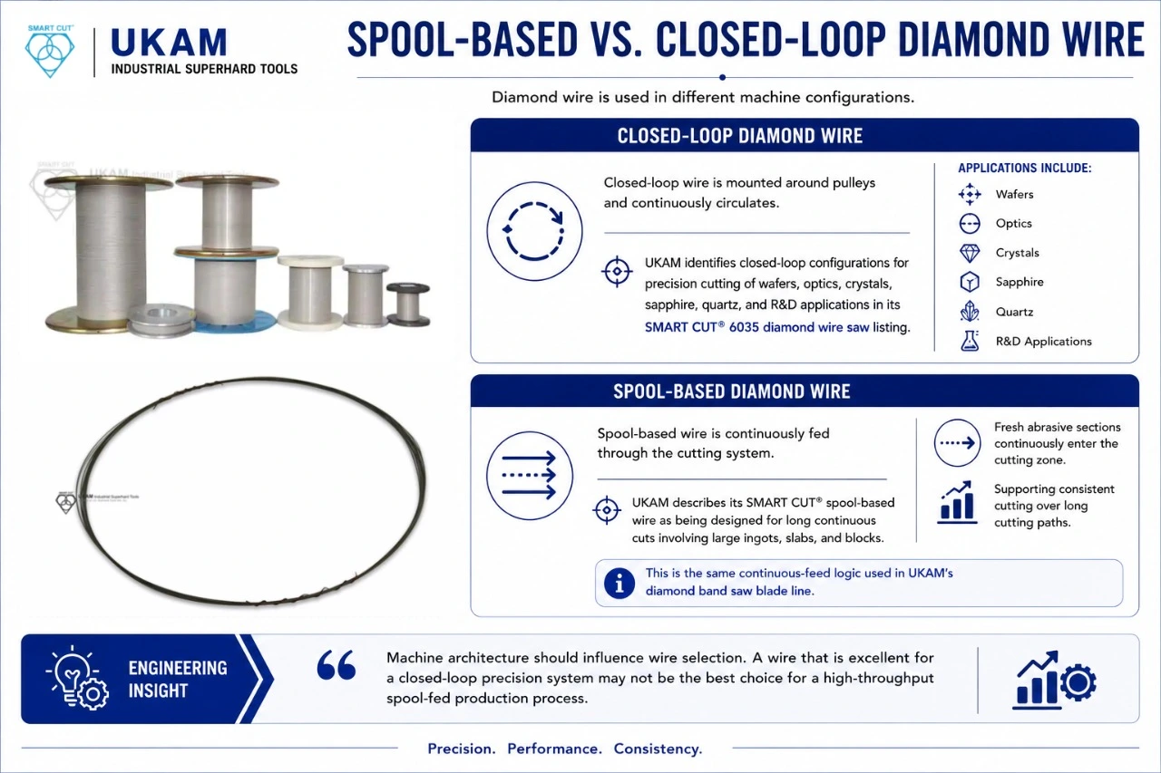
Closed-Loop Diamond Wire
Closed-loop wire is mounted around pulleys and continuously circulates. UKAM identifies closed-loop configurations for precision cutting of wafers, optics, crystals, sapphire, quartz, and R&D applications in its SMART CUT® 6035 diamond wire saw listing.
Spool-Based Diamond Wire
Spool-based wire is continuously fed through the cutting system. UKAM describes its SMART CUT® spool-based wire as being designed for long continuous cuts involving large ingots, slabs, and blocks. Fresh abrasive sections continuously enter the cutting zone, supporting consistent cutting over long cutting paths — the same continuous-feed logic used in UKAM’s diamond band saw blade line.
Engineering Insight
Machine architecture should influence wire selection. A wire that is excellent for a closed-loop precision system may not be the best choice for a high-throughput spool-fed production process.
Why Sapphire Is a Special Cutting Challenge
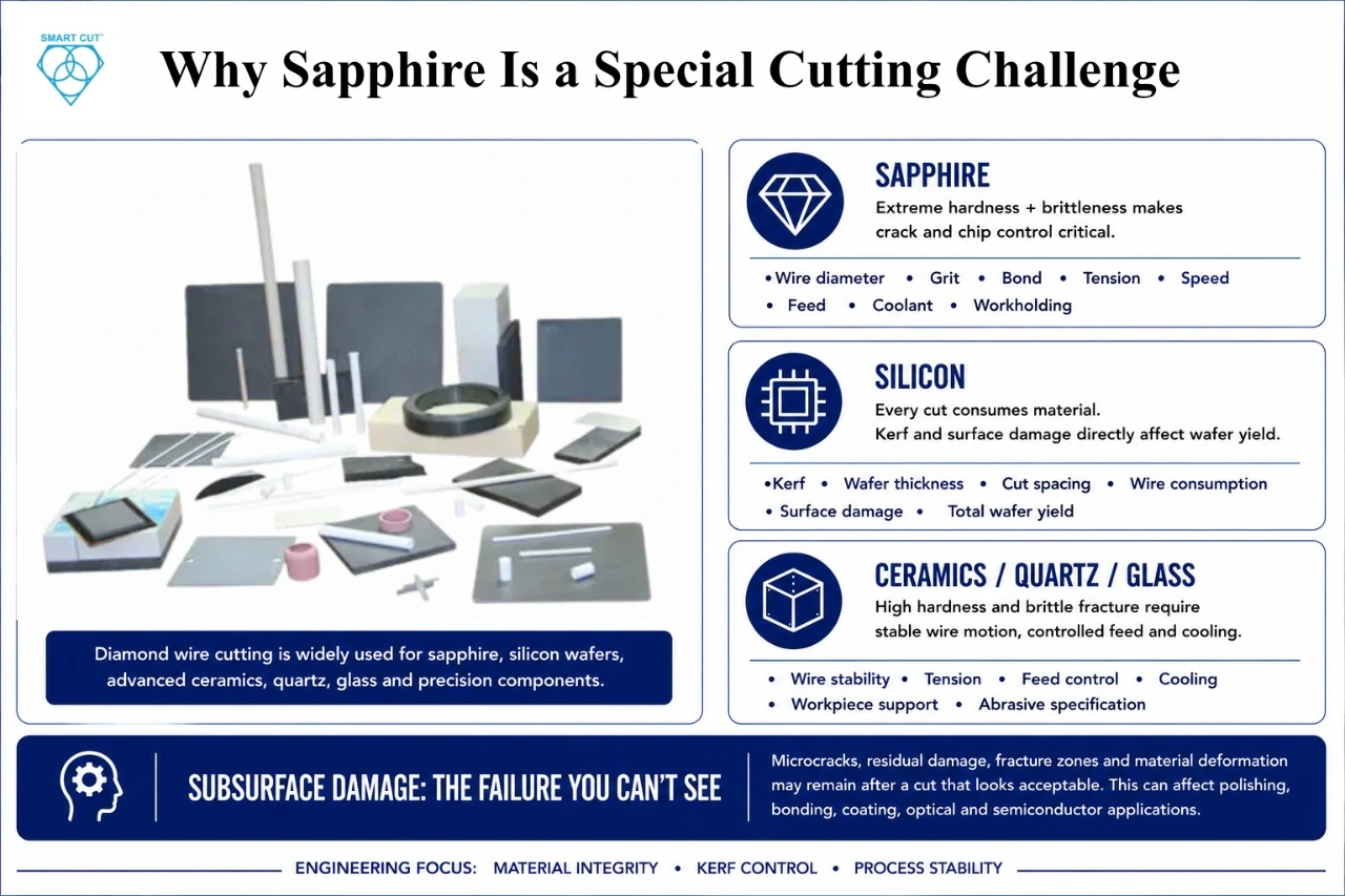
Sapphire is extremely hard and brittle.
That combination makes it a useful example of why diamond-wire selection matters.
The process must balance: Hardness → cutting efficiency, against: Brittleness → crack and chip control
For sapphire, engineers may need to evaluate: Wire diameter · Grit size · Bond type · Tension · Cutting speed · Feed pressure · Coolant · Workholding · Material geometry — the same brittle-material edge-quality trade-offs documented in UKAM’s nickel bond hubbed dicing blade overview.
UKAM specifically identifies sapphire among the materials suited to its diamond-wire cutting technology.
Silicon: The Economics of Kerf Become Critical
Silicon wafer manufacturing is particularly sensitive to material yield.
Every cut consumes some material.
Therefore, engineers should consider: Kerf · Wafer thickness · Cut spacing · Wire diameter · Cutting speed · Wire consumption · Surface damage · Total wafer yield
UKAM describes diamond wire as widely used for monocrystalline and polycrystalline silicon and identifies very low kerf loss and improved total thickness variation as advantages — figures quantified in UKAM’s dicing blade case studies.
Engineering Question
How much silicon is being converted into cutting loss rather than usable product? That question can be more financially important than the purchase price of the wire itself.
Advanced Ceramics: Precision Without Excessive Damage
Advanced ceramics can combine: High hardness · High strength · Brittleness · Abrasiveness
These properties make them challenging to machine using conventional cutting methods.
Diamond wire can provide a narrow cutting interface while allowing engineers to control cutting forces and material removal.
Potential application areas include: Technical ceramics · Aerospace components · Biomedical ceramics · Electronic substrates · Research samples
UKAM identifies specialized ceramics among the advanced applications for diamond-wire cutting, alongside closely related brittle-material tooling covered in the diamond core drills for the glass & quartz industry guide.
Quartz, Glass, and Optical Materials
Glass and quartz introduce another challenge: They can chip or crack even when the cutting force appears modest.
This means: Wire stability · Tension · Feed control · Cooling · Workpiece support · Abrasive specification — all become important.
A process that is aggressive enough to achieve reasonable cycle time must still remain controlled enough to avoid excessive edge damage, a balance also discussed in UKAM’s diamond core drills for the stone industry guide.
Subsurface Damage: The Failure You Cannot Always See
One of the most important differences between cutting quality and material quality is subsurface damage.
A cut can look acceptable under normal visual inspection and still contain: Microcracks · Residual damage · Fracture zones · Material deformation
This can become particularly important when the cut surface will later be: Polished · Bonded · Coated · Used in optical applications · Used in semiconductor processing · Subjected to thermal cycling
UKAM positions its diamond-wire technology as reducing subsurface damage and supporting smooth surfaces, potentially reducing secondary processing.
Engineering Insight
A clean-looking cut is not necessarily a damage-free cut — the same lesson applies to grinding, as covered in why diamond grinding wheels glaze and how to restore cutting performance.
How Cutting Parameters Affect Wire Performance
Diamond-wire performance is influenced by the complete cutting condition.
Key variables include:
- Wire speed — Higher speed can increase productivity but may change cutting forces, heat, and abrasive wear.
- Feed pressure — Higher pressure can increase material removal but may also increase: Wire stress · Heat · Chipping · Breakage risk
- Wire tension — Tension must be compatible with: Wire diameter · Core material · Machine · Cutting load
- Coolant — Cooling can help manage heat and debris.
- Material preparation — Poor preparation can introduce instability before cutting begins.
UKAM’s diamond-wire documentation specifically identifies speed, pressure, material preparation, weld strength, cutting fluid, wire diameter, and material as performance variables — the same set documented in the metallography & precision sample preparation abrasives guide.
Engineering Question: Why Does a Wire Break?
Wire breakage should not automatically be blamed on the wire.
Potential causes include: Excessive tension · Excessive feed pressure · Misaligned pulleys · Worn pulleys · Incorrect wire diameter · Poor weld quality · Excessive vibration · Abrasive buildup · Improper machine setup
UKAM specifically notes that worn pulleys can cause wire misalignment, increased wear, breakage, and inconsistent cutting.
Diagnostic Principle
If a wire repeatedly breaks at a similar location, investigate the machine and wire path—not just the abrasive.
Pulley Condition Can Affect Cut Quality
Pulleys determine how the wire travels.
If a pulley is worn: Wire tracking can change · Tension can fluctuate · Vibration can increase · Wire wear can accelerate · Cut accuracy can deteriorate
This is especially important for fine wire.
Engineering Checklist
Before changing wire specifications, check: Pulley groove condition · Alignment · Bearing condition · Wire tracking · Tension stability · Machine vibration — the same diagnostic framework used across UKAM’s Knowledge Center.
Cooling and Cutting Fluid
Cooling serves several purposes.
It can help: Control heat · Remove debris · Reduce friction · Stabilize the cutting interface · Protect the workpiece
UKAM emphasizes contamination-free coolant as part of its diamond-wire cutting approach and describes water-based cooling/recirculation in its diamond-wire equipment.
For sensitive semiconductor, optical, or research applications, coolant cleanliness can be as important as coolant quantity.
Engineering Question
Is the coolant helping the cutting process without introducing contamination that creates a downstream problem? That should be part of process qualification.
How Much Heat Is Too Much?
There is no single universal temperature threshold that applies to every material and application.
The acceptable thermal condition depends on: Material · Geometry · Cutting speed · Wire type · Coolant · Required material integrity · Downstream processing
UKAM’s product information describes diamond wire as generating very little heat in suitable applications and cites a typical rise of less than 10°F in its general description. That should be treated as application-specific product information, not a universal process limit.
Engineers should validate actual thermal behavior in their own process.
Illustrative Process Optimization Example
The following numbers are illustrative only.
Suppose a manufacturer is cutting a brittle ceramic and tests three conditions:
|
Metric |
Trial A |
Trial B |
Trial C |
|---|---|---|---|
|
Cutting time |
20 min |
15 min |
11 min |
|
Edge damage |
Low |
Low |
High |
|
Surface condition |
Good |
Very good |
Moderate |
|
Wire breaks |
0 |
0 |
2 |
|
Acceptable parts |
98% |
99% |
86% |
Trial C is fastest. But Trial B delivers the highest acceptable-part yield.
The correct production decision is therefore not obvious from cutting time alone.
Better metric: Acceptable parts per production hour — rather than: Raw cutting speed
Material Waste vs. Tool Cost
Suppose a diamond wire costs more than a conventional abrasive process.
That does not automatically make it more expensive overall.
The complete calculation should include: Material saved · Cutting time · Wire consumption · Labor · Machine time · Coolant · Secondary finishing · Scrap · Rework · Equipment utilization
Engineering Insight
For high-value materials, the cost of material lost during cutting can exceed the cost of the cutting consumable. That is why kerf deserves economic attention — the same economics apply across UKAM’s diamond band saw blade product line.
Diamond Wire vs. Slurry-Based Wire Sawing
Traditional abrasive slurry wire sawing uses a wire carrying loose abrasive particles in a slurry.
The slurry provides cutting action and lubrication.
Diamond wire instead incorporates diamond abrasive directly into or onto the wire.
UKAM describes diamond wire as an alternative to older slurry-based methods, highlighting advantages including faster cutting, reduced kerf loss, less secondary processing, and elimination of slurry recycling/disposal requirements.
|
Consideration |
Slurry Wire Sawing |
Diamond Wire |
|---|---|---|
|
Abrasive delivery |
Loose abrasive slurry |
Diamond fixed to wire |
|
Slurry handling |
Required |
Eliminated |
|
Kerf |
Application-dependent |
Can be very narrow |
|
Cutting speed |
Application-dependent |
Often higher |
|
Process cleanliness |
Slurry management required |
Cleaner cutting process |
|
Abrasive consistency |
Depends on slurry |
Controlled by wire |
|
Waste management |
Slurry disposal/recycling |
Reduced slurry burden |
This does not mean diamond wire is automatically superior for every application. Machine configuration and process economics still need to be evaluated — a comparison made easier using UKAM’s How to Use Our Website navigation guide.
When Is Diamond Wire the Better Choice?
Diamond wire becomes particularly attractive when the application requires: Low kerf · High material value · Precision cutting · Hard-material cutting · Reduced subsurface damage · High repeatability · Lower secondary processing · Cleaner operation
It can be particularly relevant to: Semiconductor manufacturing · Photovoltaics · Photonics · Advanced ceramics · Crystal growth · Optical manufacturing · Materials research — the sectors listed across UKAM’s Industries page.
Common Engineering Mistakes
Mistake 1: Choosing the Smallest Available Wire
A smaller diameter can reduce kerf. But it can also increase sensitivity to tension, handling, and breakage.
Better approach: Optimize wire diameter against yield, stability, and production requirements.
Mistake 2: Choosing Grit by Material Hardness Alone
Material hardness is important, but it is not the only variable.
Better approach: Consider hardness, brittleness, surface quality, cutting rate, and tool construction together.
Mistake 3: Maximizing Cutting Speed
Faster cutting can increase productivity. But it can also increase: Damage · Heat · Wire wear · Breakage
Better approach: Find the maximum stable cutting rate within the quality specification.
Mistake 4: Ignoring Wire Tension
Incorrect tension can cause instability or breakage.
Better approach: Match tension to wire diameter, core material, machine, and process.
Mistake 5: Ignoring Pulley Wear
A worn pulley can create wire-tracking problems.
Better approach: Inspect the entire wire path before changing wire specifications.
Mistake 6: Measuring Only Kerf
Low kerf does not guarantee high yield.
Better approach: Measure kerf, damage, dimensional accuracy, cutting time, and acceptable-part rate together.
Mistake 7: Ignoring Coolant Cleanliness
Contaminated coolant can create problems in sensitive applications.
Better approach: Include coolant condition and filtration in process control.
Mistake 8: Assuming Visible Quality Means No Subsurface Damage
Microcracks may not be immediately visible.
Better approach: Use appropriate inspection methods for the application.
Mistake 9: Changing Wire and Process Parameters Simultaneously
If wire type, grit, tension, feed, and speed all change together, the result becomes difficult to interpret.
Better approach: Establish a controlled baseline.
Mistake 10: Ignoring Material Economics
A cheaper wire may create more material loss.
Better approach: Calculate total cost per acceptable part.
A Practical Diamond-Wire Qualification Process
Step 1: Characterize the Material
Record: Material · Grade · Hardness · Brittleness · Abrasiveness · Workpiece dimensions · Material value
Step 2: Define the Cut
Specify: Cut length · Cut thickness · Required kerf · Dimensional tolerance · Surface requirement · Edge requirement · Subsurface-damage limit
Step 3: Define Production Requirements
Document: Cuts per hour · Acceptable-part rate · Maximum downtime · Wire consumption · Required tool life
Step 4: Evaluate the Machine
Check: Wire path · Pulley condition · Tension system · Feed mechanism · Cooling · Alignment · Vibration
Step 5: Select the Wire
Evaluate: Diameter · Core material · Grit · Bond · Abrasive distribution · Loop or spool configuration
Step 6: Establish a Baseline
Record: Cutting speed · Feed · Tension · Coolant · Kerf · Surface quality · Edge damage · Wire wear
Step 7: Optimize One Major Variable at a Time
This allows the engineering team to determine what actually improved the process.
Diamond Wire Core Material Also Matters
UKAM identifies several core materials for diamond wire, including: High-tensile steel · Stainless steel · Tungsten · Molybdenum · Specialty alloys such as NiTi and composites — covered further in UKAM’s diamond core drill & bit manufacturing overview.
These materials can provide different combinations of: Strength · Flexibility · Corrosion resistance · Heat resistance · Fatigue resistance
Engineering Question
Does the wire core have enough mechanical strength and flexibility for the machine and cutting load? This becomes especially important when working with fine wire.
Fine Wire for Semiconductor and Optical Applications
Fine wire can be attractive when material preservation and precision are priorities.
UKAM identifies fine-wire configurations for: Semiconductor wafers · Sapphire · Optics — with fine wire approximately 75–180 µm and diamond grit around 10–30 µm in its usage recommendations.
Such fine wire can reduce kerf, but the machine must provide sufficient control.
Fine wire demands attention to: Tension · Pulley diameter · Alignment · Vibration · Feed · Wire handling
Medium Wire for Glass and Ceramics
UKAM identifies medium wire approximately 240–340 µm with diamond grit around 30–40 µm for applications such as: Solar wafers · Glass · Ceramics — matched by grit and material in the same way as UKAM’s SMART CUT electroplated nickel bond hole saw / core drill line.
This illustrates how wire specifications can be matched to the balance between:
Cutting efficiency + material preservation + process stability
Large Wire for Blocks and Ingots
Larger wire configurations can be appropriate when the application involves: Large blocks · Silicon ingots · Stone · Composites · Longer cutting paths
UKAM’s current usage recommendations identify approximately 340–420 µm wire with 40–50 µm diamond grit for such applications — the type of large-format cutting documented across UKAM’s diamond wire & band saw blade blog archive.
For long cuts, spool-based wire can also provide a continuous supply of fresh abrasive.
When Should You Consider Custom Diamond Wire?
Standard wire specifications can be suitable for many applications.
But custom wire may be worth considering when the application requires a particular combination of: Wire diameter · Core material · Diamond grit · Bond · Tensile strength · Loop length · Spool length · Cutting environment · Machine configuration
- Wire diameter
- Core material
- Diamond grit
- Bond
- Tensile strength
- Loop length
- Spool length
- Cutting environment
- Machine configuration
UKAM states that its diamond-wire products are available in different configurations and can be made to order; its Custom Diamond & CBN Tool Manufacturing capability is a core part of the broader product catalog.
Engineering Insight
Custom wire becomes valuable when standard wire forces a compromise between material yield, cutting speed, quality, or tool life.
When Should You Change the Wire?
Don’t change wire simply because cutting speed has decreased. First ask:
Has the wire worn?
Look for: Reduced cutting efficiency · Increased cutting time · Surface-quality deterioration · Increased heat · Increased wire breakage
Has the machine changed?
Check: Pulley wear · Tension · Alignment · Bearings · Vibration
Has the material changed?
Check: Material grade · Hardness · Thickness · Surface condition
Has the process changed?
Check: Feed · Speed · Coolant · Pressure · Workpiece support
This diagnostic approach can prevent unnecessary tooling changes, and mirrors the same troubleshooting logic used in UKAM’s Photonics tooling overview for optical-material cutting drift.
Diamond Wire Troubleshooting Table
|
Problem |
Possible Causes |
First Checks |
|---|---|---|
|
Wire breaks |
Excessive tension, misalignment, worn pulley |
Tension + wire path |
|
Cutting slows |
Abrasive wear, loading, poor parameters |
Wire condition + process |
|
Excessive chipping |
High force, vibration, unsuitable grit |
Feed + tension + wire |
|
High kerf |
Oversized wire, excessive wear |
Wire diameter + condition |
|
Poor surface finish |
Grit/bond mismatch, vibration |
Wire specification + machine |
|
Excessive heat |
High load, poor cooling |
Feed + coolant |
|
Dimensional variation |
Tension instability, pulley wear |
Machine alignment |
|
Short wire life |
Excessive pressure, wrong wire |
Pressure + material compatibility |
How to Measure Process Success
A production team should establish measurable acceptance criteria.
- Cutting — Cutting time · Feed rate · Wire speed
- Material — Kerf · Material loss · Breakage · Yield
- Quality — Surface finish · Edge damage · Subsurface damage · Dimensional accuracy · TTV where relevant
- Tool — Wire consumption · Wire breaks · Tool life
- Economics — Cost per cut · Cost per acceptable part · Secondary processing · Scrap · Downtime
Illustrative Production Scorecard
The following values are illustrative only.
|
Metric |
Target |
Trial Result |
|---|---|---|
|
Kerf |
≤ 0.25 mm |
0.21 mm |
|
Acceptable parts |
≥ 97% |
98% |
|
Average cutting time |
≤ 18 min |
16 min |
|
Wire breaks |
≤ 1 / 100 cuts |
0 |
|
Secondary finishing |
Low |
Low |
|
Surface quality |
Within spec |
Within spec |
This type of scorecard is more useful than saying “the new wire cuts faster.” It shows whether the complete process improved — the same scorecard discipline UKAM applies across its Shop catalog.
Frequently Asked Questions
UKAM lists diamond-wire applications for silicon, sapphire, SiC, glass, GaAs, germanium, CaF₂, crystals, magnetic materials, tungsten-containing materials, ceramics, and other hard or brittle materials.
Diamond wire can provide a narrow cutting interface and is particularly useful for hard and brittle materials. Its low kerf can reduce material loss, while its abrasive cutting action can support precision applications.
Kerf loss is the material removed by the cutting path. A narrower kerf generally means less material is consumed by the cut, although the complete process must also be evaluated for speed, damage, and stability.
The appropriate diameter depends on material, required kerf, cutting length, machine capability, tension, production requirements, and desired quality.
No. Finer grit can support certain surface-quality requirements, but the correct grit must balance cutting efficiency, material behavior, surface quality, and tool life.
Electroplated wire holds diamond particles in a metal plating layer, while resin-bond wire embeds diamond in a resin matrix that can gradually wear to expose fresh abrasive. Each construction has different cutting characteristics and application considerations.
Possible causes include excessive tension, high feed pressure, pulley wear, misalignment, vibration, incorrect wire specification, or machine problems.
Start by examining feed, tension, wire specification, machine stability, coolant, workholding, and material condition. The correct solution depends on where and when the chipping occurs.
UKAM states that diamond wire can be reused to some extent depending on material, cutting speed, tension, and wire quality, although abrasive wear eventually requires replacement.
Yes. UKAM notes that diamond-wire cutting can be automated for consistent and repeatable cutting, and its SMART CUT® 6035 system provides automated X/Y control and adjustable feed speeds.
Diamond wire can eliminate the need for abrasive slurry recycling and disposal. UKAM specifically positions its diamond-wire process as a cleaner alternative to slurry-based cutting.
Final Engineering Takeaways
When cutting silicon, sapphire, ceramics, quartz, glass, or other hard and brittle materials, the diamond wire should be treated as part of a complete process.
The important variables include: Wire diameter · Core material · Diamond grit · Bond · Abrasive distribution · Wire tension · Cutting speed · Feed pressure · Coolant · Pulley condition · Workholding · Material condition
And the key performance indicators are: Kerf + material yield + cut quality + dimensional accuracy + wire life + throughput — not simply cutting speed.
A successful diamond-wire process should produce the required cut while minimizing: Material waste · Chipping · Subsurface damage · Wire breakage · Secondary processing · Downtime
The most important question is therefore not:
“What is the fastest diamond wire?”
It is:
“What diamond-wire specification provides the best combination of material yield, cut quality, process stability, and production economics for this specific material and machine?”
Need Help Selecting Diamond Wire for Your Application?
If your current cutting process is experiencing: Excessive kerf loss · Sapphire or ceramic chipping · Silicon material waste · Subsurface damage · Poor dimensional accuracy · Short wire life · Frequent wire breakage · Excessive cutting time · High secondary-processing requirements
the solution may not be simply increasing cutting speed or changing wire diameter.
The wire’s diameter, diamond grit, bond, core material, tension, machine configuration, coolant, and cutting parameters need to be considered together.
UKAM provides diamond wire in multiple configurations for precision and production cutting, including fine wires for semiconductor, sapphire, and optical applications, medium wires for glass and ceramics, and larger wire configurations for silicon ingots, composites, and other large workpieces. The company also offers spool-based and closed-loop configurations and custom manufacturing capabilities.
For an application-specific evaluation, provide: Material and grade · Workpiece dimensions · Required cut thickness · Required kerf · Cutting depth · Required dimensional accuracy · Surface-finish requirement · Chipping/subsurface-damage limit · Current wire diameter · Current wire construction · Cutting speed · Feed/pressure · Wire tension · Coolant · Machine type · Current wire life · Current failure mode · Production volume
That information allows the wire specification to be matched to the actual cutting problem rather than selected from diameter alone.
The objective is not simply to find a diamond wire that can cut the material. It is to develop a cutting process that preserves valuable material, maintains part quality, and delivers repeatable production.
Trusted by Tens of Thousands of Manufacturers, Laboratories,
Research Institutions Worldwide Since 1990
American Based Manufacturer
Established in 1990
