Workholding for Precision Diamond Sectioning and Dicing

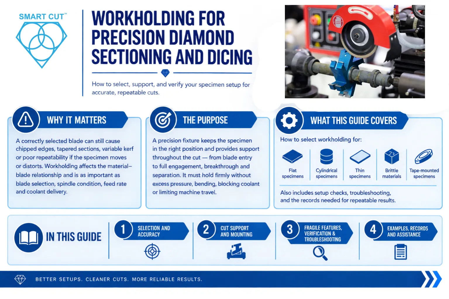
Table of Contents
ToggleA correctly selected diamond blade can still produce chipped edges, tapered sections, variable kerf, or poor dimensional repeatability when the specimen moves or distorts during cutting. Workholding directly affects the relationship between the material and the blade. It deserves the same attention as blade selection, spindle condition, feed rate, and coolant delivery.
The purpose of a precision fixture is to maintain the required specimen position and support throughout the cut. This includes blade entry, full engagement, breakthrough, and separation of the finished section. A setup must provide adequate restraint without introducing damaging pressure, bending the specimen, blocking coolant, or interfering with machine travel.
This guide explains how to select workholding for flat, cylindrical, thin, brittle, irregular, and tape-mounted specimens. It also covers practical setup checks, troubleshooting, and the records needed to reproduce a successful process. Use the recommendations with the requirements of your specific machine, fixture, blade, and material.
In this guide
Trusted by Tens of Thousands of Manufacturers, Laboratories Research Institutions Worldwide Since 1990

American Based Manufacturer

Established in 1990


Custom manufacturing


Start with the specimen and the required cut
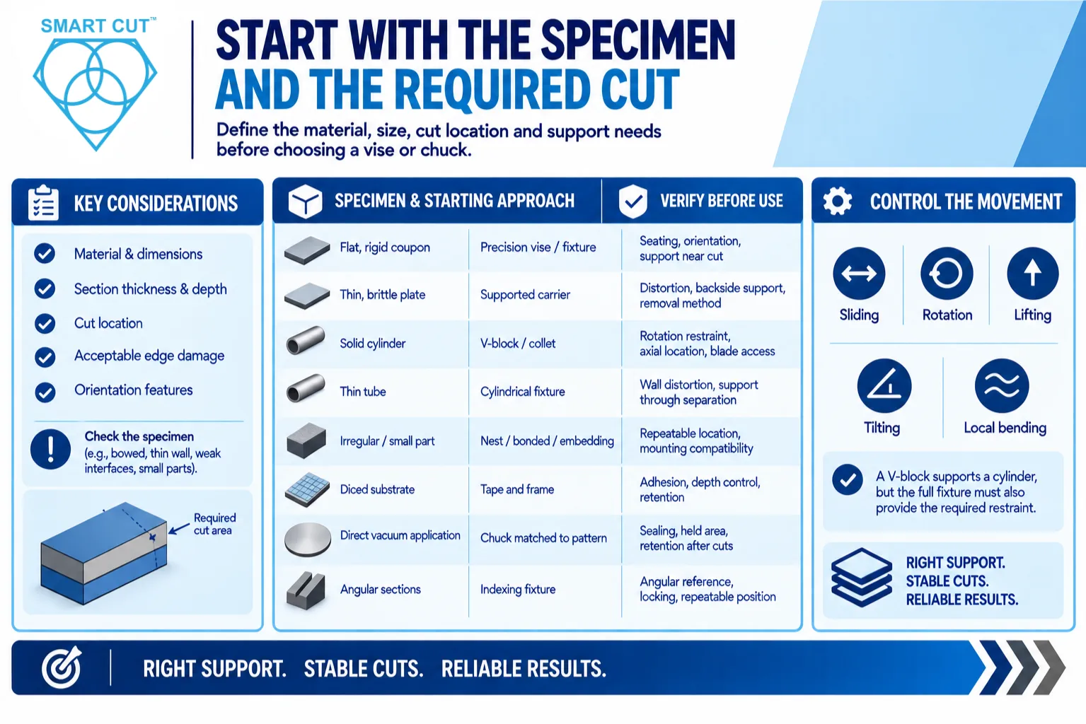
Before choosing a vise or chuck, define the result you need. Identify the material, specimen dimensions, desired section thickness, cutting depth, cut location, and acceptable edge damage. Establish which surfaces or features define the required orientation. A fixture can hold a specimen securely while positioning the cut incorrectly.
Consider the condition of the specimen as well as its nominal shape. A ceramic plate may be bowed. A tube may have a thin or variable wall. A multilayer assembly may contain a weak interface that cannot tolerate concentrated pressure. A small mounted component may have too little exposed surface for direct clamping.
Plan what will support both the retained specimen and the section being removed. The support requirement changes as the remaining connection becomes smaller. For repeated cuts, evaluate the complete sequence. Removing one section may alter the support, available gripping area, or retention of the next section.
Use the selection matrix as a starting point. Each approach requires confirmation against the actual specimen, cutting forces, machine configuration, and acceptance criteria.
| Specimen | Starting approach | Verify before use |
|---|---|---|
| Flat, rigid coupon | Precision vise or locating fixture | Stable seating, cut orientation, and support near the cut |
| Thin, brittle plate | Supported carrier or suitable distributed holding | Distortion, backside support, and removal method |
| Solid cylinder | Clamped V-block or suitable collet | Rotation restraint, axial location, and blade access |
| Thin tube | Supported cylindrical fixture | Wall distortion and support through separation |
| Irregular or small part | Contoured nest, bonded carrier, or embedding | Repeatable location and mounting compatibility |
| Diced substrate | Suitable tape and frame on an approved chuck | Adhesion, depth control, and retention of every piece |
| Direct vacuum application | Chuck matched to the specimen and cut pattern | Sealing, effective held area, and retention after cuts |
| Angular sections | Lockable indexing fixture | Angular reference, locking, and repeatable positioning |
The workholding method should control the movement relevant to your application. These movements include sliding, rotation, lifting, tilting, and local bending. A V-block establishes a useful support geometry for a cylinder, but the complete fixture must also provide the required restraint. Likewise, broad contact alone does not prove that a thin specimen will remain stable.
How workholding affects accuracy
Cutting forces change with material, blade engagement, feed, cutting depth, and blade condition. A specimen that shifts under those forces can change the cut location or orientation. Local movement can also increase blade side loading, vibration, and edge damage.
Alignment and stiffness have different functions. Alignment establishes the intended relationship between the specimen and the cutting plane. Stiffness helps maintain that relationship under load. Check both. A rigid fixture can hold a misaligned specimen consistently, while a correctly aligned but flexible setup can change position during cutting.
The distance between the support and the cutting zone also matters. An unsupported projection can bend even when its opposite end is tightly clamped. Deeper cuts or greater blade engagement can place additional demands on the setup. Evaluate the actual cut geometry rather than assuming that a fixture suitable for a shallow cut will perform equally well at greater depth.
The machine, blade, workpiece, fixture, coolant, and operating parameters interact. A change in any one can affect the result. If performance changes after a fixture adjustment, examine the new support and alignment conditions before deciding that a different blade specification is required.
Control clamping pressure without distorting the specimen
Insufficient restraint can allow slipping, rotation, or vibration. Excessive clamping can crush a fragile edge, distort a thin part, damage a coating, or force a specimen into a shape it will not retain after release. The objective is stable retention within the material’s allowable stress and deformation limits.
Position the clamp so that its load is reacted by appropriate support. Avoid pressing on an unsupported thin region. Increase useful contact area where the specimen permits, and avoid burrs, sharp jaw edges, or uneven contacts that concentrate the load.
Protective pads and jaw liners need controlled properties. Select a material compatible with the specimen, coolant, and required cleanliness. Keep its thickness and stiffness consistent. A very compliant layer can protect a surface while allowing movement or creep. Confirm that the assembled interface maintains position throughout the cutting cycle.
For recurring work, record the clamp location, tightening sequence, jaw arrangement, and applicable torque or actuator-pressure setting. Use settings established for the particular fixture and specimen. There is no universal tightening torque for brittle materials. Screw torque is also not a direct measurement of specimen clamping force because friction and mechanism geometry affect the relationship.
Inspect the specimen after clamping and after release. Visible distortion is a reason to investigate, but the absence of visible bending does not establish dimensional accuracy. Where tolerances require it, measure the relevant geometry in the clamped and released conditions using a suitable inspection method.
Select the mechanical fixture for the geometry
Vises for flat and rectangular specimens
A precision vise can provide convenient seating and restraint when the specimen has suitable contact surfaces. Check jaw condition, parallelism, available contact area, and the relationship between the jaws and the cutting plane. Confirm that the selected grip leaves enough access for the blade and coolant.
For brittle plates, avoid relying on a narrow contact at an edge or corner. Support the specimen close enough to the cutting region to control bending, while preserving the planned clearance. A vise with sufficient opening capacity may still be unsuitable if the specimen cannot seat predictably against its reference surfaces.
V-blocks and collets for cylindrical specimens
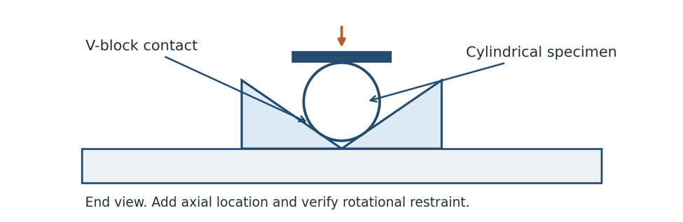
A V-block supports a cylinder at defined contact regions. Add suitable clamping and axial location for the intended cutting direction. A collet can provide circumferential restraint when its size, engagement length, and construction suit the component. Neither method removes the need to check angular orientation and blade clearance.
Thin tubes require particular care. A gripping arrangement suitable for a solid rod can deform the tube wall. Evaluate distributed contact and, where appropriate, internal support. Any internal support must also be considered in the cutting path and subsequent specimen removal. Confirm that the holding method does not change the feature you intend to examine.
Irregular specimens and dedicated fixtures
For an irregular component, identify stable locating surfaces before applying clamping force. A contoured nest, adjustable support, bonded carrier, or dedicated fixture may provide a more predictable arrangement than a standard vise. Avoid forcing the component against incompatible locating points.
A useful dedicated fixture establishes repeatable location, adequate support, accessible clamping, and a clear cutting path. Include drainage, cleaning access, and practical loading and unloading. For repeated production, make the intended orientation easy to recognize and document the fixture revision used.
Indexed and rotating workholding
Indexing establishes a defined angular position between cuts. A fixture used for indexing must retain the selected position during the cut. Check the locking method, angular reference, and repeatability after repositioning.
Some machine configurations also permit intentional specimen rotation during cutting. Treat this as a separate operating mode with its own approved settings and clearance requirements. Do not assume that a chuck intended for angular positioning supports powered rotation during blade engagement. Unintended rotation remains a setup failure.
Support the cutting zone and the separated section
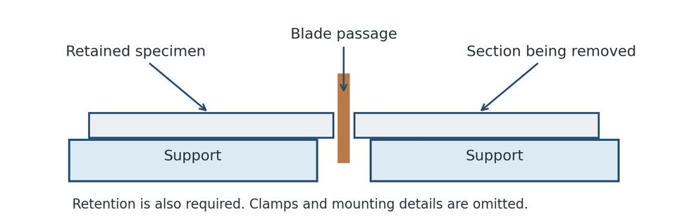
Backside support can help control bending and reduce the tendency for a brittle edge to break away as the blade exits. Locate support in relation to the cut and the blade’s actual entry and exit geometry. Simply adding a plate elsewhere under the specimen may not support the vulnerable region.
Also identify how the finished section will be retained at breakthrough. A loose section can drop, rotate, or contact the blade after the final material bridge disappears. Suitable methods may include a compatible backing arrangement, a bonded carrier, dicing tape, or an approved secondary holding arrangement.
Avoid assuming that both sides should always be clamped tightly. The arrangement must account for possible stress release and movement during separation. Misaligned or unsuitable restraint can load the blade or allow the kerf to close. Support the pieces in a way that suits the material and machine, without imposing an uncontrolled force across the cut.
Distinguish permanent fixture components from sacrificial support. The blade must clear permanent chuck surfaces, clamps, and fasteners. An intentionally cut sacrificial layer may be included in a validated process when the layer material, thickness, and blade penetration are appropriate. Its presence can affect blade loading, contamination, and cut quality.
Define the permitted penetration into the sacrificial layer and the clearance beneath it. Account for specimen thickness variation, mounting thickness, and the machine’s depth-setting method. Inspect or replace the support when previous cuts, embedded debris, or damage prevent reliable seating.
Dicing tape, frames, and retention after separation
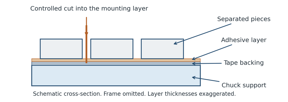
In a common tape-mounted dicing arrangement, the specimen adheres to dicing tape supported by a frame. The machine’s chuck supports and holds the mounted assembly according to its design. The adhesive retains the individual pieces as the cutting pattern separates them. These functions must work together throughout the process.
Select tape for the specimen surface, required adhesion, coolant exposure, cutting conditions, and removal method. Initial tack alone is not a complete selection criterion. The mounting must retain the smallest separated pieces through the full cutting pattern and any subsequent handling or cleaning included in the process.
Apply the tape using a suitable mounting procedure. Inspect for wrinkles, trapped particles, bubbles, and areas of incomplete contact. Check frame seating and the flatness of the supported assembly. Uneven mounting can create local differences in support or effective cutting depth.
Set the depth using the machine’s approved procedure and the actual mounting stack. Where the process intentionally cuts into tape, control penetration so that the substrate separates without unintended damage to the holding system. Excessive penetration can compromise tape integrity or create a vacuum leakage path. Insufficient depth can leave connected regions between pieces.
Evaluate retention after the first cuts and after the second cutting direction where applicable. A setup that holds an intact plate successfully may behave differently after it becomes an array of small pieces. Adhesion, piece dimensions, cutting forces, and fluid exposure all belong in that evaluation.
Plan removal before selecting the tape. Where a release treatment is part of the tape system, confirm its compatibility with the specimen and use the specified process. Establish handling and removal steps that protect the finished edges and sensitive surfaces. Stronger adhesion is not automatically better when it increases damage during release.
Vacuum workholding for thin and flat specimens
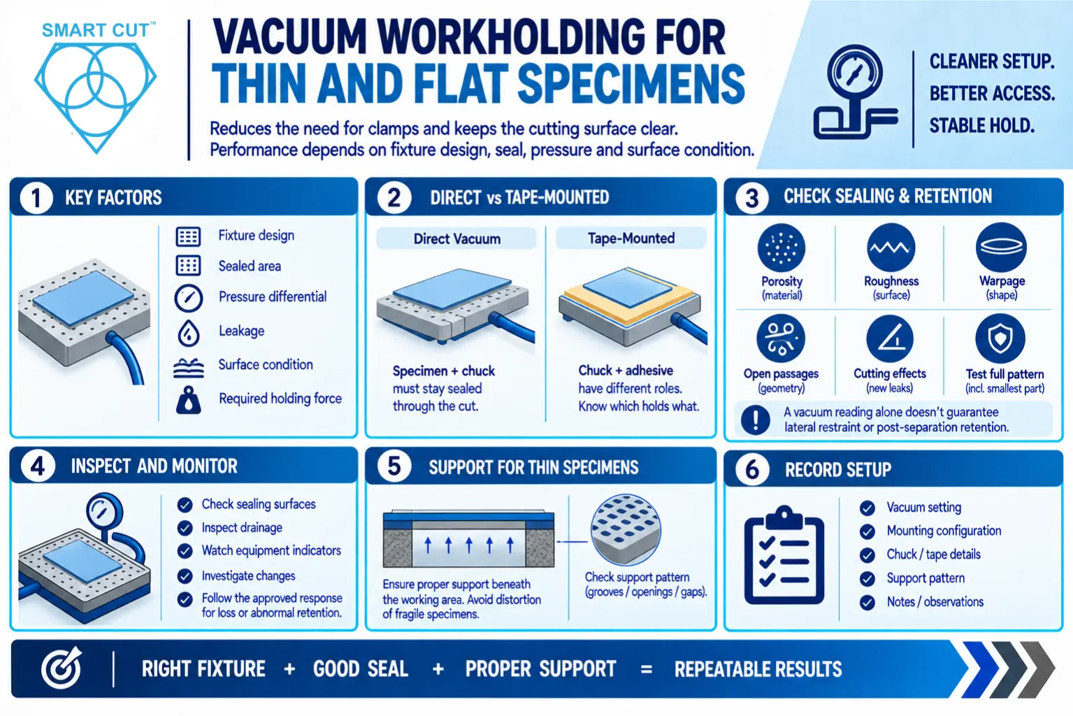
Vacuum holding can reduce the need for local mechanical clamps and preserve access to the cutting surface. Its suitability depends on the fixture design, effective sealed area, pressure differential, leakage, surface condition, and the forces that the assembly must resist.
Separate direct vacuum holding from tape-mounted or carrier-mounted holding. Direct holding requires the specimen and chuck arrangement to maintain adequate retention through the cut. In a tape-mounted setup, the chuck and adhesive perform different roles. Confirm which interface holds the assembly and which retains the separated pieces.
Porosity, roughness, warpage, open passages, and changing part geometry can affect sealing. Cutting can introduce new leakage paths or reduce the effectively held area. Verify retention for the complete pattern, including the smallest remaining section. An acceptable initial vacuum reading does not by itself demonstrate adequate lateral restraint or post-separation retention.
Inspect sealing surfaces and drainage arrangements. In tape-mounted systems, a punctured tape or liquid entering an unintended interface can affect vacuum performance. Monitor the indicators provided by the equipment and investigate changes before continuing. Use the approved response to vacuum loss or abnormal retention.
For thin specimens, confirm that the chuck provides suitable support beneath the working area. Evaluate the effect of grooves, openings, or gaps in the support pattern. Distributed suction should not force a fragile specimen into an unacceptable shape. Record the established vacuum setting and the relevant mounting configuration.
Temporary bonding, wax mounting, and embedding
Small or irregular specimens may not offer enough surface for reliable mechanical clamping. Temporary bonding to a carrier can provide support and a larger interface for handling. Wax, suitable adhesives, and embedding media offer different options, but their suitability depends on the specimen and the purpose of the examination.
For a bonded carrier, control the mounting layer and ensure adequate contact near the cut. Uneven thickness, voids, or contamination can affect support and orientation. Confirm that the carrier can be located securely and that the entire stack fits the required blade and flange clearance.
For wax mounting, establish a temperature range that allows preparation and removal without altering the specimen. For adhesive mounting, confirm curing requirements, resistance to coolant, and the release process. Consider whether residue or cleaning chemicals could interfere with later microscopy, bonding, coating, or dimensional inspection.
Embedding a specimen in a mounting medium is a different process from bonding it to a carrier. It may help support small features or provide a convenient geometry for clamping. Evaluate curing heat, shrinkage, infiltration, and removal requirements. A mounting method that changes the interface under investigation can make the prepared section unsuitable for analysis.
If the blade cuts through the mounting medium or carrier, include that material in blade and parameter selection. Establish a trial procedure using representative material when possible. Record the mounting material, relevant preparation conditions, and the method used to recover and clean the finished section.
Protect coatings, interfaces, and fragile features
For coated or multilayer materials, choose locating and clamping surfaces with the interface of interest in mind. Avoid loading an unsupported coating edge or using clamping pressure to flatten an assembly with internal weakness. Determine whether the feature can tolerate direct contact, mounting heat, or removal chemicals.
Plan specimen orientation and support for the point where the blade approaches and exits the interface. The best orientation depends on the layer arrangement, cutting direction, and failure mechanism. Do not apply a universal orientation rule to every coating or composite.
Inspect the prepared section for damage that could be mistaken for an original material defect. Compare the cut edge and relevant interface with the acceptance criteria established before cutting. When a specimen is unique, document its initial condition and orientation with photographs before mounting.
Verify seating, clearance, and coolant access
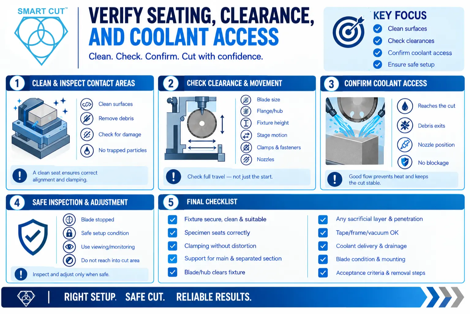
Clean the specimen contact areas, jaws, reference surfaces, chuck, and support plates before mounting. Remove loose particles and residue using a method appropriate for the equipment and specimen. Inspect for burrs, dents, corrosion, embedded abrasive, and wear. A trapped particle can change the seating angle even when the specimen feels secure.
Check the complete moving assembly over the intended travel using the machine’s approved setup procedure. Include blade diameter, cutting-edge thickness, flange or hub envelope, fixture height, stage motion, clamps, fasteners, and coolant nozzles. Clearance at the starting position does not establish clearance at maximum engagement.
Confirm that coolant reaches the cutting interface throughout the cut and that debris can leave the working area. A mechanically rigid fixture can still create an unstable process if it blocks delivery or traps cutting debris. Check the actual nozzle arrangement after clamping, since the fixture can change the available flow path.
Perform physical inspection and adjustment only with the blade stopped and the machine in the required safe setup condition. Do not reach into the cutting area to test retention during operation. Observe the cut through the equipment’s intended viewing and monitoring provisions.
Use this checklist before the first cut and after a significant setup change.
- The fixture is securely mounted, clean, and suitable for the specimen.
- The specimen seats against the intended reference surfaces in the correct orientation.
- Clamping or mounting follows the established method without unacceptable distortion.
- Support and retention are provided for the main specimen and the separated section.
- The complete blade and flange or hub envelope clears permanent fixture components.
- Any sacrificial layer and intended penetration are included in the depth setting.
- Tape contact, frame seating, and vacuum conditions are acceptable where applicable.
- Coolant delivery and drainage remain effective over the entire cut.
- Blade condition and mounting have passed the required initial inspection.
- Acceptance criteria, first-cut inspection, and specimen-removal steps are defined.
Validate the setup with measurable results
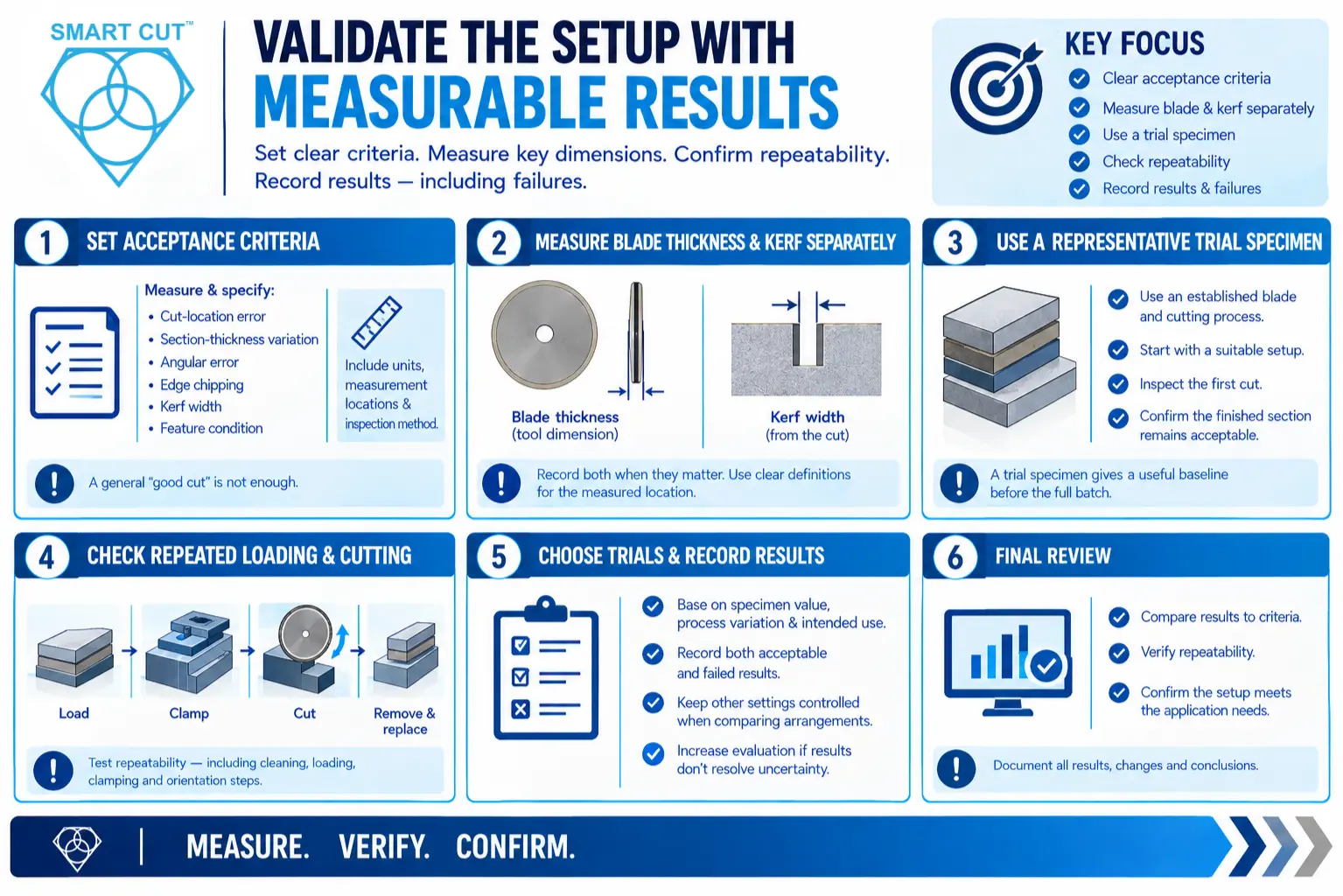
Define acceptance criteria before evaluating a fixture. Possible measures include cut-location error, section-thickness variation, angular error, edge chipping, kerf width, and the condition of the feature being examined. Specify the units, measurement locations, and inspection method. A general description such as “good cut” is not sufficient for a repeatable qualification.
Measure blade thickness and kerf separately. Blade thickness describes a tool dimension. Kerf is the width produced by the cutting process and must be evaluated from the cut using an appropriate method. Record both when they matter to the application, with clear definitions for the measured location.
Use a representative trial specimen when available. Start with an established, suitable blade and cutting process so the workholding evaluation has a useful baseline. Inspect the first cut before committing the complete batch. Confirm that the finished section remains acceptable after release from the fixture or mounting medium.
Evaluate repeated loading as well as repeated cutting. Several cuts from one untouched setup do not establish how consistently the specimen seats after removal and replacement. For recurring work, include the normal cleaning, loading, clamping, and orientation steps in the repeatability evaluation.
Choose the number of trials according to the value of the specimen, process variation, and intended use. Record failures as well as acceptable results. When comparing arrangements, keep other influential settings controlled and document every change. Use a larger evaluation when the initial results do not resolve the remaining uncertainty.
Troubleshoot changes in cut quality
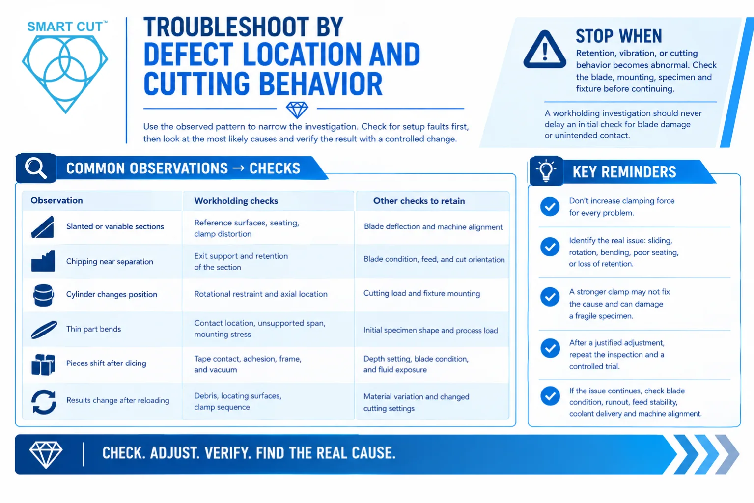
Stop when retention, vibration, or cutting behavior becomes abnormal. Follow the equipment procedure and inspect blade integrity, mounting, the specimen, and the fixture before continuing. A workholding investigation should never delay an initial check for blade damage or unintended contact.
After the initial condition check, investigate the most likely causes using the observed symptom and recent changes. Examine seating, support, restraint, alignment, coolant, operating parameters, and machine condition. Blade specification and condition remain part of that investigation. One symptom can have several contributing causes.
| Observation | Workholding checks | Other checks to retain |
|---|---|---|
| Slanted or variable sections | Reference surfaces, seating, clamp distortion | Blade deflection and machine alignment |
| Chipping near separation | Exit support and retention of the section | Blade condition, feed, and cut orientation |
| Cylinder changes position | Rotational restraint and axial location | Cutting load and fixture mounting |
| Thin part bends | Contact location, unsupported span, mounting stress | Initial specimen shape and process load |
| Pieces shift after dicing | Tape contact, adhesion, frame, and vacuum | Depth setting, blade condition, and fluid exposure |
| Results change after reloading | Debris, locating surfaces, clamp sequence | Material variation and changed cutting settings |
Avoid responding to every problem by increasing clamping force. First identify whether the issue is sliding, rotation, bending, poor seating, or loss of retention after separation. A stronger clamp may leave the actual cause unchanged or damage a fragile specimen.
After a justified adjustment, repeat the relevant inspection and a controlled trial. Compare the same measurements at the same locations. If correcting the workholding does not resolve the problem, investigate blade condition, runout, feed stability, coolant delivery, and machine alignment without assuming a single cause.
Three illustrative application examples
The following examples show how to structure an evaluation. They are illustrative scenarios, not measured production results or guaranteed improvements.
Thin ceramic plate with exit-edge chipping
The plate is held securely at one end, but the cutting region projects beyond its support. Edge damage increases near separation. Before changing the blade, inspect blade condition, specimen seating, and the unsupported region. Evaluate a compatible backing or carrier arrangement that supports the vulnerable area and retains the section being removed.
Keep the established cutting parameters controlled during the comparison. Measure the exit-edge damage using the same magnification and locations. Also check section thickness and flatness after release. Accept the new arrangement only when the required measurements meet the defined limits. Improvement alone does not establish acceptance.
Thin tube with inconsistent section geometry
A tube is held in a general-purpose vise and shows variable section geometry. Examine whether it rotates, seats inconsistently, or deforms under jaw pressure. Evaluate a correctly sized cylindrical fixture with appropriate axial location and distributed restraint. Consider internal support only when it suits the cutting and removal process.
Compare the tube geometry before clamping and after release. Measure the finished section’s orientation and dimensions. Repeat the loading operation to confirm that the result depends on a reproducible setup rather than one favorable seating position.
Tape-mounted substrate with moving pieces
An intact substrate appears stable, but small pieces shift during later cuts. Examine tape contact, mounting cleanliness, frame seating, vacuum behavior, and programmed depth. Determine whether the smallest pieces retain adequate adhesion throughout the complete cutting pattern and associated fluid exposure.
Evaluate a suitable mounting correction while controlling the remaining process variables. Inspect piece retention, cut location, and edge condition after each relevant stage. Include removal from the tape in the evaluation so the selected method protects the pieces through the entire process.
Record the workholding configuration
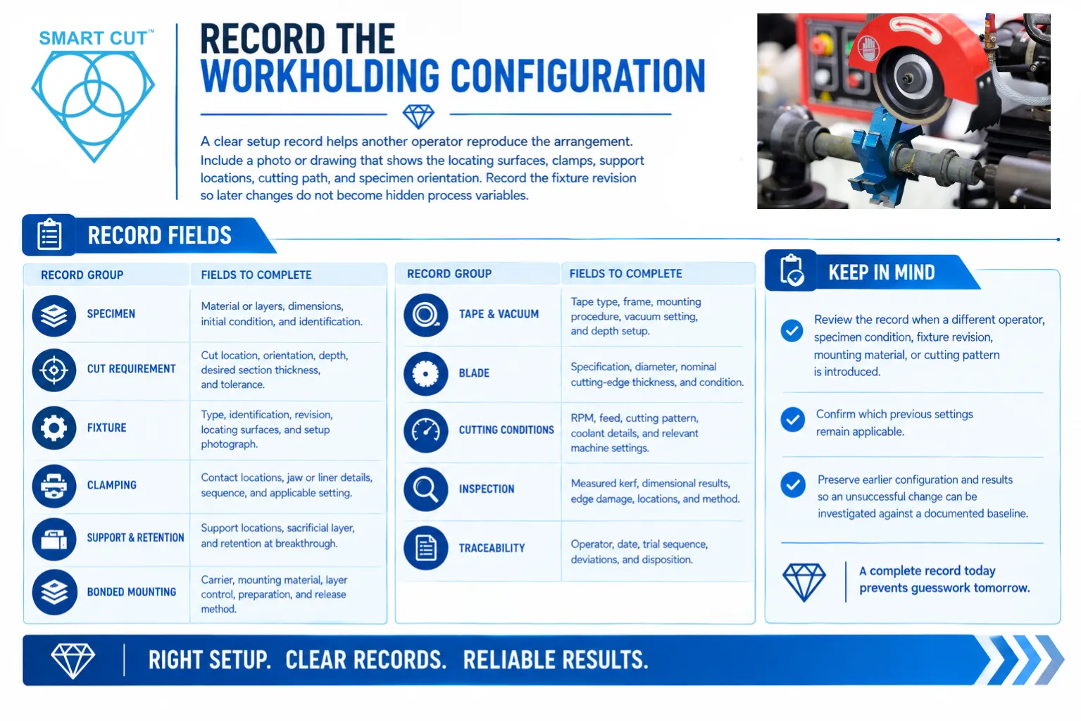
A useful setup record lets another operator reconstruct the arrangement. Include a photograph or drawing that identifies the locating surfaces, clamp positions, support locations, intended cutting path, and specimen orientation. Record the fixture revision so later changes do not become hidden process variables.
Use the fields below with the established cutting record. Enter the actual values and units. Where a field does not apply, mark it accordingly rather than leaving its meaning uncertain.
| Record group | Fields to complete |
|---|---|
| Specimen | Material or layers, dimensions, initial condition, and identification |
| Cut requirement | Cut location, orientation, depth, desired section thickness, and tolerance |
| Fixture | Type, identification, revision, locating surfaces, and setup photograph |
| Clamping | Contact locations, jaw or liner details, sequence, and applicable setting |
| Support and retention | Support locations, sacrificial layer, and retention at breakthrough |
| Bonded mounting | Carrier, mounting material, layer control, preparation, and release method |
| Tape and vacuum | Tape type, frame, mounting procedure, vacuum setting, and depth setup |
| Blade | Specification, diameter, nominal cutting-edge thickness, and condition |
| Cutting conditions | RPM, feed, cutting pattern, coolant details, and relevant machine settings |
| Inspection | Measured kerf, dimensional results, edge damage, locations, and method |
| Traceability | Operator, date, trial sequence, deviations, and disposition |
Review the record whenever a different operator, specimen condition, fixture revision, mounting material, or cutting pattern is introduced. Confirm which previous settings remain applicable. Preserve the earlier configuration and results so an unsuccessful change can be investigated against a documented baseline.
Request an application-specific workholding review
For difficult geometries, fragile materials, valuable specimens, or recurring sectioning work, evaluate the workholding together with the blade and machine. A dedicated arrangement may be worthwhile when it improves repeatable positioning, reduces handling difficulty, or helps protect a feature that standard clamping cannot support reliably.
UKAM Industrial Superhard Tools can help you review precision diamond blades, cutting systems, and the workholding requirements of your application. Available configurations depend on the specimen and selected equipment. Describe the process requirement so the review can address support, restraint, blade access, and the intended cut together.
To request assistance, provide your material and layer structure, specimen dimensions, machine, blade specification, desired section thickness, cut depth, dimensional tolerance, and acceptable edge damage. Include photographs or a drawing showing the current holding method and planned cut. Identify any limits on mounting temperature, surface contact, contamination, or removal chemicals.
Related UKAM resources: Precision cutting systems | Diamond dicing blades | Coolant selection and application | Request applications assistance
Trusted by Tens of Thousands of Manufacturers, Laboratories,
Research Institutions Worldwide Since 1990
American Based Manufacturer
Established in 1990
Custom manufacturing
RELATED ARTICLES