How Thin Kerf Diamond Blades Improve Material Yield and Reduce Kerf Loss

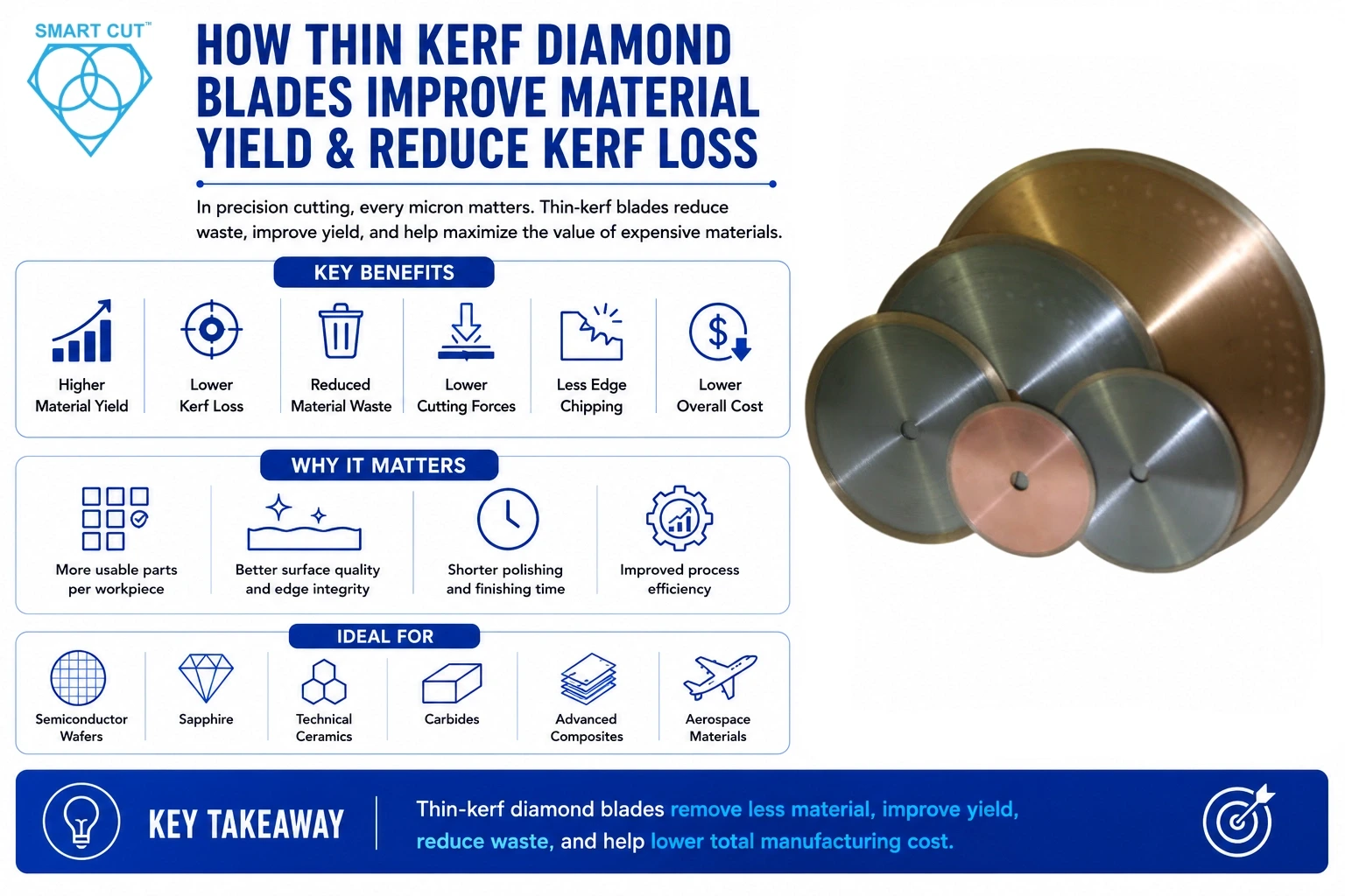
Table of Contents
ToggleIn precision cutting operations, every micron of material matters.
Whether sectioning semiconductor wafers, sapphire substrates, technical ceramics, advanced composites, carbides, or high-value aerospace materials, the width of the cut, known as the kerf, directly impacts material yield, production costs, machining efficiency, and overall profitability.
While many manufacturers focus on blade life, spindle speed, feed rate, or machine rigidity, kerf loss often remains an overlooked source of unnecessary material waste.
For low-cost materials, the effect may be minimal. However, when cutting expensive engineering materials such as monocrystalline silicon, silicon carbide, gallium arsenide, sapphire, tungsten carbide, or advanced ceramics, even small reductions in kerf width can significantly increase the number of usable parts produced from each workpiece.
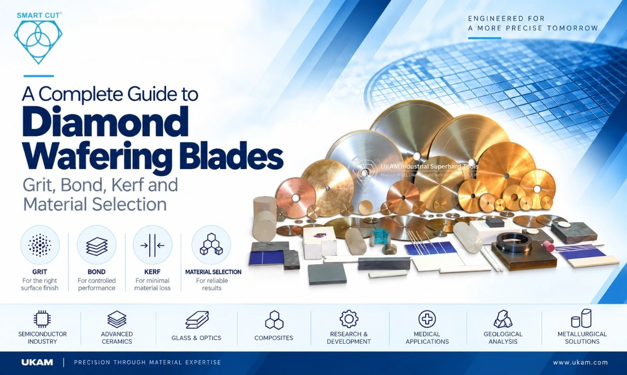
Thin kerf diamond blades are specifically engineered to minimize material removal while maintaining precision, stability, and repeatability. By reducing the amount of material converted into waste during every cut, these blades help manufacturers improve yield, lower consumable costs, shorten downstream finishing operations, and maximize the value of expensive raw materials.
Beyond reducing waste, thinner blades also lower cutting forces, reduce heat generation, minimize edge chipping, and decrease subsurface damage, benefits that are especially important for brittle materials where preserving structural integrity is critical.
For semiconductor manufacturers, research laboratories, metallography facilities, medical device manufacturers, electronics companies, and precision machining operations, selecting the appropriate thin-kerf diamond blade can influence:
Material utilization
Production yield
Surface quality
Edge integrity
Blade life
Cutting stability
Polishing time
Overall manufacturing cost
This article explains the engineering principles behind thin-kerf technology, examines how kerf width affects production economics, and provides practical guidance for selecting the appropriate blade configuration to improve both process efficiency and material yield.
Trusted by Tens of Thousands of Manufacturers, Laboratories Research Institutions Worldwide Since 1990

American Based Manufacturer

Established in 1990


Custom manufacturing


Why Kerf Loss Matters in Precision Cutting
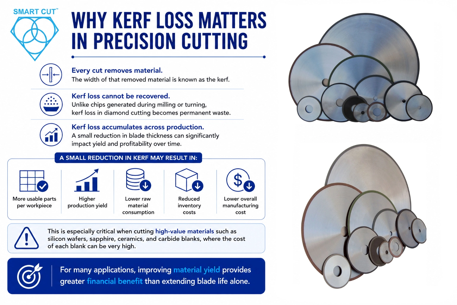
Every cut removes material.
The width of that removed material is known as the kerf.
Unlike chips generated during milling or turning, kerf loss in diamond cutting cannot be recovered. Every micron removed becomes permanent waste.
For manufacturers processing expensive engineering materials, kerf loss accumulates rapidly across production.
Consider a facility cutting hundreds or thousands of silicon wafers, sapphire substrates, ceramic components, or carbide blanks each month.
A small reduction in blade thickness may allow:
- More usable parts per workpiece
- Higher production yield
- Lower raw material consumption
- Reduced inventory costs
- Lower overall manufacturing cost
This becomes particularly important when working with materials costing hundreds or thousands of dollars per blank.
For many applications, improving material yield provides greater financial benefit than extending blade life alone.
Understanding Kerf Loss
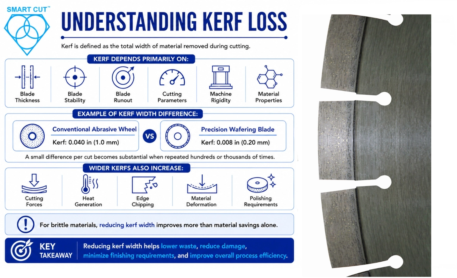
Kerf is defined as the total width of material removed during cutting.
It depends primarily on:
Blade thickness
Blade stability
Blade runout
Cutting parameters
Machine rigidity
Material properties
For example:
A conventional abrasive wheel with a kerf of 0.040 in (1.0 mm) removes significantly more material than a precision wafering blade with a kerf of 0.008 in (0.20 mm).
Although the difference appears small for a single cut, it becomes substantial when repeated hundreds or thousands of times.
For brittle materials, wider kerfs also increase:
Cutting forces
Heat generation
Edge chipping
Material deformation
Polishing requirements
Reducing kerf width, therefore, improves on material savings alone.
Why Thin Kerf Diamond Blades Improve Material Yield
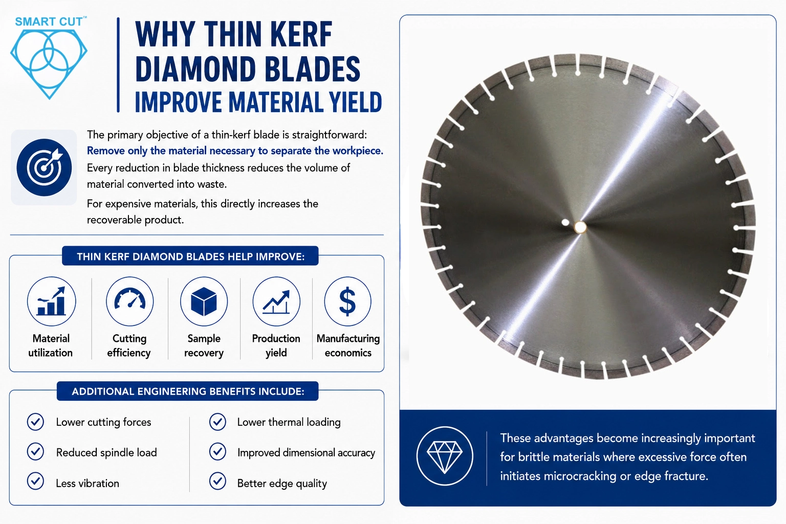
The primary objective of a thin-kerf blade is straightforward:
Remove only the material necessary to separate the workpiece.
Every reduction in blade thickness reduces the volume of material converted into waste.
For expensive materials, this directly increases the recoverable product.
Thin kerf diamond blades help improve:
Material utilization
Cutting efficiency
Sample recovery
Production yield
Manufacturing economics
Additional engineering benefits include:
- Lower cutting forces
- Reduced spindle load
- Less vibration
- Lower thermal loading
- Improved dimensional accuracy
- Better edge quality
These advantages become increasingly important for brittle materials where excessive force often initiates microcracking or edge fracture.
Engineering Principles Behind Thin-Kerf Technology
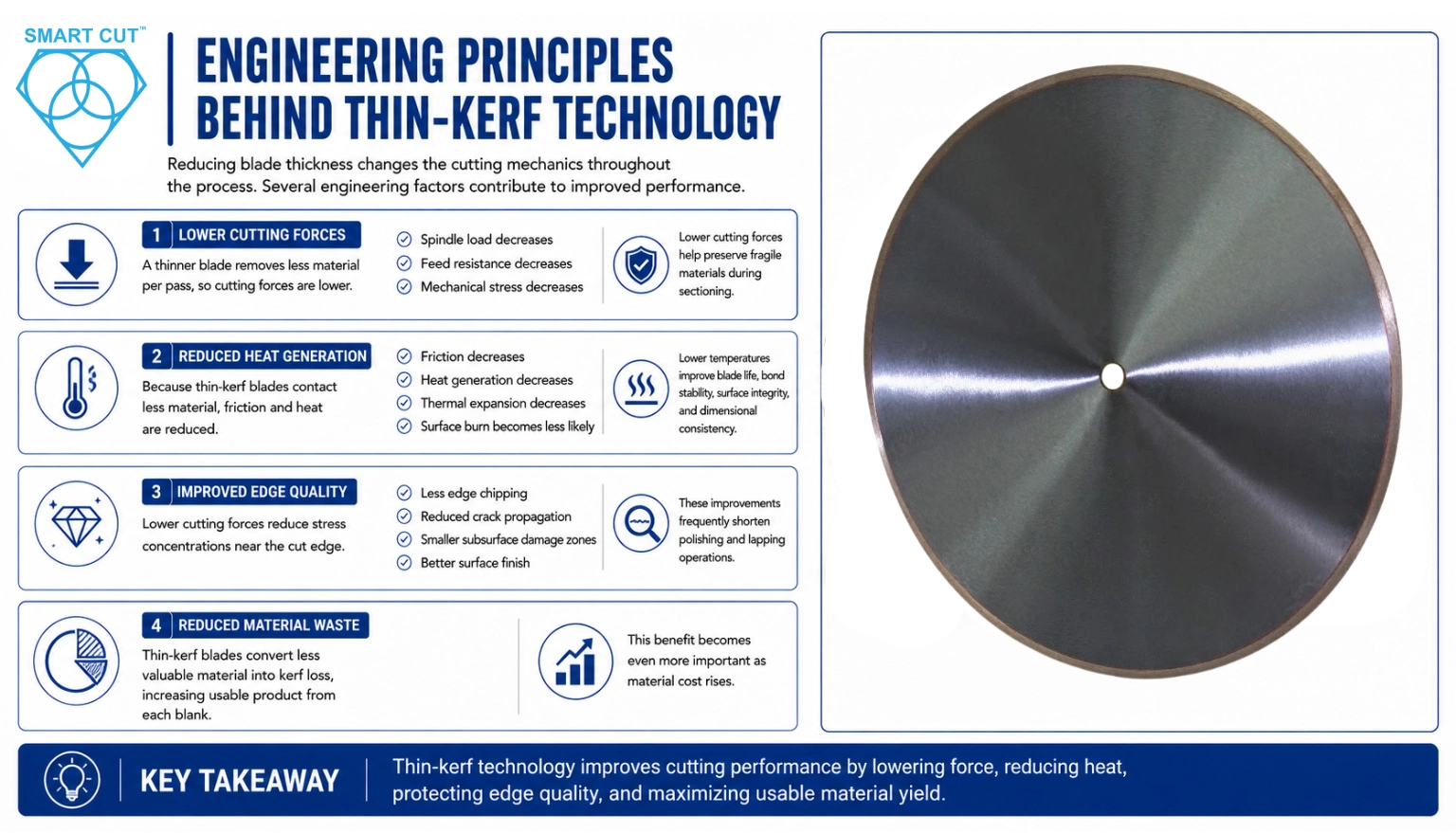
Reducing blade thickness changes the cutting mechanics throughout the process.
Several engineering factors contribute to improved performance.
Lower Cutting Forces
Cutting force is proportional to the volume of material removed.
A thinner blade removes less material per pass.
As a result:
Spindle load decreases
Feed resistance decreases
Mechanical stress decreases
Lower cutting forces help
preserve fragile materials during sectioning.
Reduced Heat Generation
Heat generation depends largely on friction.
Since thin-kerf blades contact less material:
Friction decreases
Heat generation decreases
Thermal expansion decreases
Surface burn becomes less likely
Lower temperatures improve:
Blade life
Bond stability
Surface integrity
Dimensional consistency
Improved Edge Quality
Lower cutting forces reduce stress concentrations near the cut edge.
For brittle materials, this often results in:
Less edge chipping
Reduced crack propagation
Smaller subsurface damage zones
Better surface finish
These improvements frequently shorten polishing and lapping operations.
Reduced Material Waste
Perhaps the greatest advantage is improved yield.
Instead of converting valuable material into kerf loss, manufacturers retain more usable product from each blank.
This benefit increases as material cost rises.
Material Cost Implications of Kerf Loss
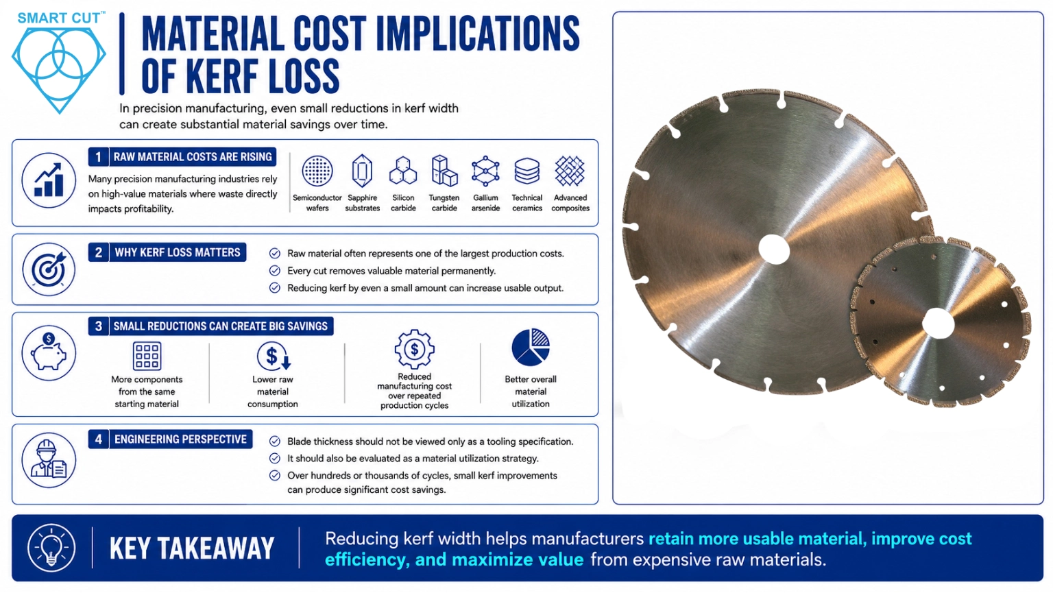
Raw material costs continue to increase across many precision manufacturing industries.
Examples include:
Semiconductor wafers
Sapphire substrates
Silicon carbide
Tungsten carbide
Gallium arsenide
Technical ceramics
Advanced composites
In these applications, raw material often represents one of the largest production costs.
Reducing kerf by even a small amount may allow manufacturers to produce additional components from the same starting material.
Over hundreds or thousands of production cycles, these improvements may significantly reduce overall manufacturing cost.
Rather than viewing blade thickness solely as a tooling specification, engineers should evaluate it as a material utilization strategy.
Yield Improvement Calculations
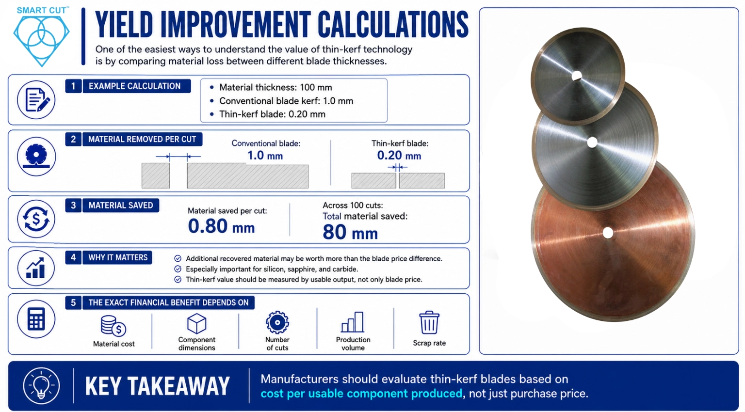
One of the easiest ways to understand the value of thin-kerf technology is by comparing material loss between different blade thicknesses.
Example Calculation
Assume:
- Material thickness: 100 mm
- Conventional blade kerf: 1.0 mm
- Thin-kerf blade: 0.20 mm
Material removed per cut:
Conventional blade:
1.0 mm
Thin-kerf blade:
0.20 mm
Material saved per cut:
0.80 mm
Across 100 cuts:
Total material saved:
80 mm
For expensive materials such as silicon, sapphire, or carbide, recovering this additional material may provide significantly greater economic value than the cost difference between blades.
The exact financial benefit depends on:
- Material cost
- Component dimensions
- Number of cuts
- Production volume
- Scrap rate
Rather than evaluating blades solely on purchase price, manufacturers should consider cost per usable component produced.
Thin-Kerf vs Conventional Diamond Blades
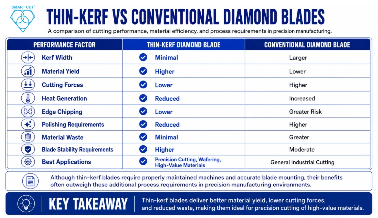
| Performance Factor | Thin-Kerf Diamond Blade | Conventional Diamond Blade |
|---|---|---|
| Kerf Width | Minimal | Larger |
| Material Yield | Higher | Lower |
| Cutting Forces | Lower | Higher |
| Heat Generation | Reduced | Increased |
| Edge Chipping | Lower | Greater Risk |
| Polishing Requirements | Reduced | Higher |
| Material Waste | Minimal | Greater |
| Blade Stability Requirements | Higher | Moderate |
| Best Applications | Precision Cutting, Wafering, High-Value Materials | General Industrial Cutting |
Although thin-kerf blades require properly maintained machines and accurate blade mounting, their benefits often outweigh these additional process requirements in precision manufacturing environments.
Material-Specific Recommendations
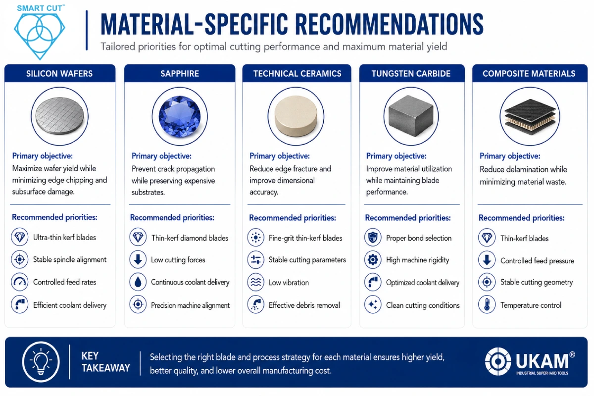
Silicon Wafers
Primary objective:
Maximize wafer yield while minimizing edge chipping and subsurface damage.
Recommended priorities:
Ultra-thin kerf blades
Stable spindle alignment
Efficient coolant delivery
Sapphire
Primary objective:
Prevent crack propagation while preserving expensive substrates.
Recommended priorities:
Low cutting forces
Continuous coolant delivery
Precision machine alignment
Technical Ceramics
Primary objective:
Reduce edge fracture and improve dimensional accuracy.
Recommended priorities:
Fine-grit thin-kerf blades
Stable cutting parameters
Low vibration
Effective debris removal
Tungsten Carbide
Primary objective:
Improve material utilization while maintaining blade performance.
Recommended priorities:
Proper bond selection
High machine rigidity
Optimized coolant delivery
Clean cutting conditions
Composite Materials
Primary objective:
Reduce delamination while minimizing material waste.
Recommended priorities:
Thin-kerf blades
Controlled feed pressure
Stable cutting geometry
Temperature control
Factors Beyond Blade Thickness That Influence Material Yield
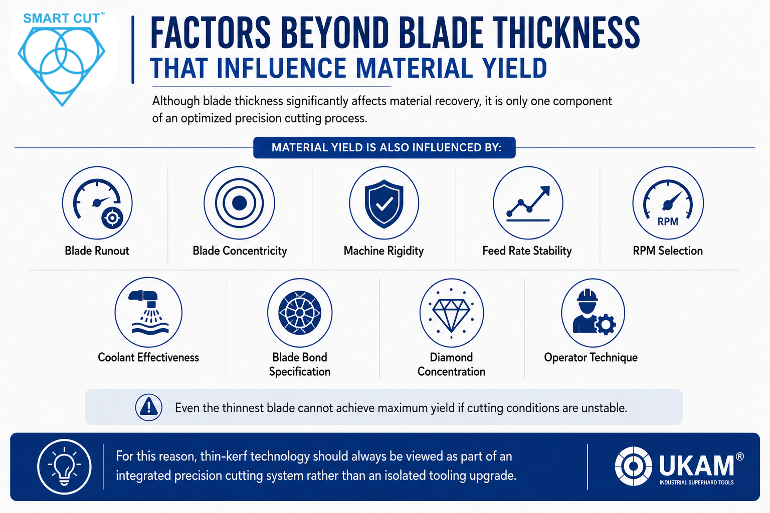
Although blade thickness significantly affects material recovery, it is only one component of an optimized precision cutting process.
Material yield is also influenced by:
Blade runout
Blade concentricity
Machine rigidity
Feed rate stability
RPM selection
Coolant effectiveness
Blade bond specification
Diamond concentration
Operator technique
Even the thinnest blade cannot achieve maximum yield if cutting conditions are unstable.
For this reason, thin-kerf technology should always be viewed as part of an integrated precision cutting system rather than an isolated tooling upgrade.
Common Mistakes That Reduce Material Yield
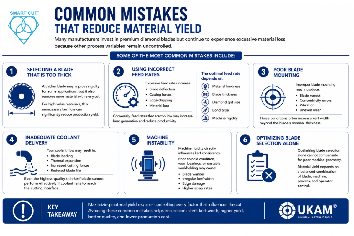
Many manufacturers invest in premium diamond blades but continue to experience excessive material loss because other process variables remain uncontrolled.
Some of the most common mistakes include:
Selecting a Blade That Is Too Thick
A thicker blade may improve rigidity for some applications, but it also removes more material with every cut.
For high-value materials, this unnecessary kerf loss can significantly reduce production yield.
Using Incorrect Feed Rates
Excessive feed rates increase:
Cutting forces
Edge chipping
Material loss
Conversely, feed rates that are too low may increase heat generation and reduce productivity.
The optimal feed rate depends on:
Material hardness
Blade thickness
Diamond grit size
Bond type
Machine rigidity
Poor Blade Mounting
Improper blade mounting may introduce:
Blade runout
Concentricity errors
Vibration
Uneven wear
These conditions often increase kerf width beyond the blade’s nominal thickness.
Inadequate Coolant Delivery
Poor coolant flow may result in:
Blade loading
Thermal expansion
Increased cutting forces
Reduced blade life
Even the highest-quality thin-kerf blade cannot perform effectively if coolant fails to reach the cutting interface.
Machine Instability
Machine rigidity directly influences kerf consistency.
Poor spindle condition, worn bearings, or unstable workholding may cause:
- Blade wander
- Irregular kerf width
- Edge damage
- Higher scrap rates
Optimizing blade selection alone cannot compensate for poor machine geometry.
Engineering Case Study: Improving Material Yield Through Thin-Kerf Technology
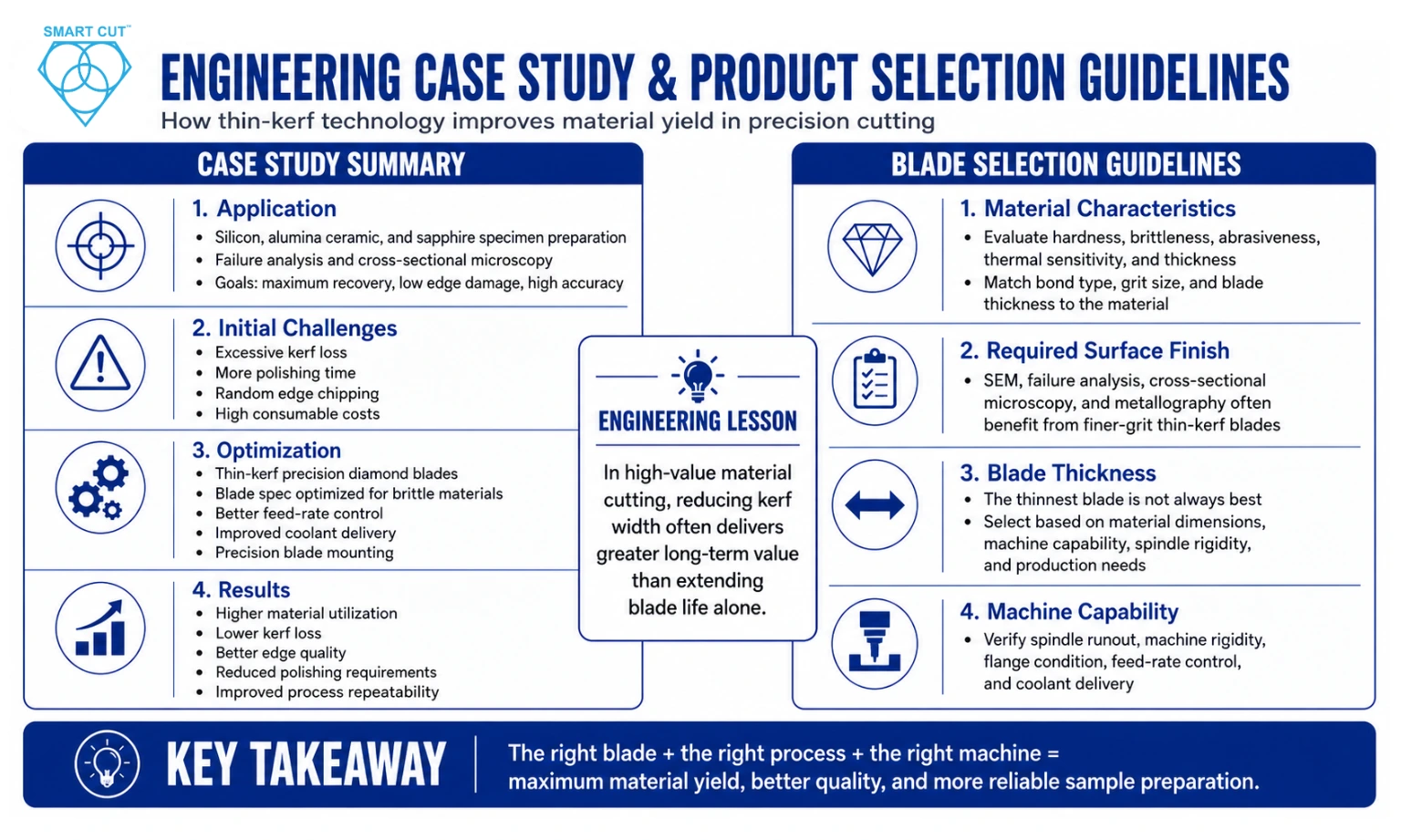
Application
A research laboratory was preparing silicon, alumina ceramic, and sapphire specimens for failure analysis and cross-sectional microscopy.
The laboratory required:
Maximum sample recovery
Minimal edge damage
High dimensional accuracy
Consistent process repeatability
Initial Challenges
The laboratory experience:
Excessive kerf loss
Increased polishing time
Random edge chipping
High consumable costs
Reduced usable samples from expensive substrates
Engineering Investigation
A review of the cutting process identified several contributing factors:
Conventional diamond blades with relatively wide kerf
Higher-than-necessary cutting forces
Excessive material removal
Longer polishing cycles after sectioning
Although blade life was acceptable, material utilization remained below expectations.
Process Optimization
The laboratory implemented:
Thin-kerf precision diamond blades
Optimized blade specification for brittle materials
Improved feed-rate control
Enhanced coolant delivery
Precision blade mounting procedures
Results
Following optimization,
engineers observed:
Improved material utilization
Lower kerf loss
Better edge quality
Reduced polishing requirements
More consistent sample preparation
Improved overall process repeatability
Engineering Lesson
In precision cutting applications involving expensive materials, reducing kerf width often provides greater long-term economic value than extending blade life alone.
Material yield should therefore be considered a primary blade selection criterion rather than simply a secondary benefit.
Note: Actual production data, yield improvements, and application photographs can be incorporated where available to strengthen this case study further.
Product Selection Guidelines
Selecting the correct thin-kerf diamond blade requires balancing material preservation with cutting stability.
Engineers should evaluate:
Material Characteristics
Consider:
Hardness
Brittleness
Abrasiveness
Thermal sensitivity
Thickness
Different materials require different combinations of bond type, grit size, and blade thickness.
Required Surface Finish
Applications requiring:
SEM analysis
Failure analysis
Cross-sectional microscopy
Metallography
typically benefit from finer-grit, thin-kerf blades that minimize subsurface damage.
Blade Thickness
The thinnest blade is not always the best blade.
Blade thickness should be selected according to:
Material dimensions
Machine capability
Spindle rigidity
Production requirements
Extremely thin blades require greater machine precision and proper operating parameters.
Machine Capability
Before selecting an ultra-thin blade, verify:
Spindle runout
Machine rigidity
Flange condition
Feed-rate control
Precision tooling performs best when supported by precision equipment.
Thin-Kerf Blade Selection Guide
| Application | Recommended Blade Characteristics |
|---|---|
| Silicon Wafers | Ultra-thin kerf, fine grit, precision bond |
| Sapphire | Thin kerf, controlled feed, high rigidity |
| Technical Ceramics | Fine grit, thin kerf, stable coolant delivery |
| Carbides | Thin kerf with wear-resistant bond |
| Metallography | Precision wafering blade with low cutting forces |
| Electronic Packaging | Thin kerf, minimal edge chipping, high accuracy |
Cost Considerations Beyond Blade Price
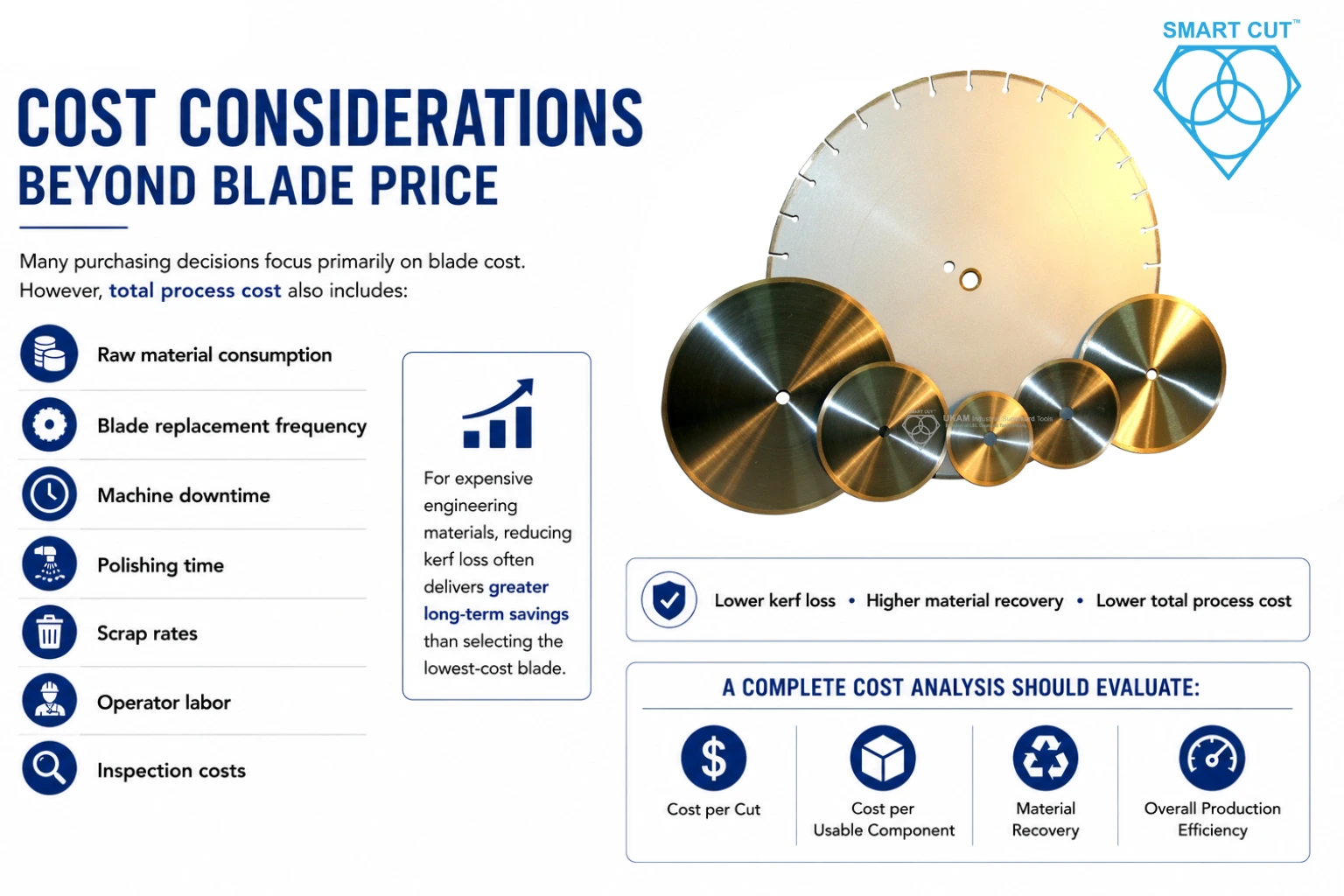
Many purchasing decisions focus primarily on blade cost.
However, total process cost also includes:
Raw material consumption
Blade replacement frequency
Machine downtime
Polishing time
Scrap rates
Operator labor
Inspection costs
For expensive engineering materials, reducing kerf loss often delivers greater long-term savings than selecting the lowest-cost blade.
A complete cost analysis should evaluate:
Cost per cut
Cost per usable component
Material recovery
Overall production efficiency
Recommended UKAM Solutions
Optimizing material yield requires more than selecting a thinner blade.
The most effective precision cutting systems typically combine:
- Thin Kerf Diamond Blades
- Precision Wafering Blades
- Precision Cutting Saws
- Optimized Coolant Systems
- Proper Blade Mounting
- Application-Specific Process Optimization
The appropriate solution depends on:
- Material type
- Component dimensions
- Surface finish requirements
- Production volume
- Machine capability
- Quality objectives
UKAM’s applications engineering team can assist in selecting blade specifications and optimizing cutting parameters to maximize material recovery and process efficiency.
Frequently Asked Questions
Kerf loss is the amount of material permanently removed during cutting and is determined primarily by blade thickness and cutting conditions.
They minimize material waste, reduce cutting forces, and improve material yield while maintaining precision.
Not necessarily. Blade thickness should be matched to the application, material properties, and machine capability.
High-value materials such as:
Silicon
Sapphire
Technical ceramics
Tungsten carbide
Quartz
Advanced composites
often benefit significantly.
Lower cutting forces frequently reduce edge chipping, particularly when combined with proper feed rates, spindle stability, and coolant delivery.
A wider kerf removes more valuable material, reducing the number of usable parts that can be produced from each workpiece.
Material yield is also
affected by:
Blade runout
Concentricity
Machine rigidity
Feed rate
RPM
Coolant delivery
Blade specification
In many applications, lower cutting forces help improve surface quality and reduce polishing requirements.
Blade life depends on multiple process variables. Proper application and operating conditions are essential for maximizing performance.
No. Blade selection should always consider the material, machine capability, and production objectives.
Optimize:
Blade specification
Kerf width
Feed rate
RPM
Coolant delivery
Machine alignment
rather than relying on blade thickness alone.
Blade selection should be based on:
Material type
Thickness
Surface finish requirements
Production volume
Machine capability
Required tolerances
Application-specific engineering guidance is often the most reliable approach.
Need Help Selecting the Right Thin-Kerf Diamond Blade?
Choosing the appropriate blade depends on:
Material characteristics
Component dimensions
Machine capability
Required tolerances
Surface finish requirements
Production objectives
UKAM’s applications engineering team can help recommend the most suitable thin-kerf diamond blade, precision wafering blade, and cutting parameters to maximize material yield while maintaining exceptional cut quality and process consistency.
Conclusion
For manufacturers processing expensive engineering materials, kerf loss is more than a machining characteristic; it is a significant economic consideration.
Thin kerf diamond blades provide a practical solution by minimizing material waste, reducing cutting forces, improving edge quality, and increasing production yield without compromising precision.
When combined with appropriate machine rigidity, spindle accuracy, coolant delivery, and optimized cutting parameters, thin-kerf technology helps improve:
Material utilization
Surface integrity
Process repeatability
Production efficiency
Cost per usable component
Rather than evaluating blade selection solely on purchase price or blade life, manufacturers should consider the overall impact on material recovery, process stability, and total manufacturing cost.
For precision cutting applications involving silicon wafers, sapphire, technical ceramics, carbides, composites, and other advanced materials, optimizing kerf width remains one of the most effective ways to increase yield and maximize the value of every workpiece.
Trusted by Tens of Thousands of Manufacturers, Laboratories,
Research Institutions Worldwide Since 1990
American Based Manufacturer
Established in 1990
Custom manufacturing
RELATED ARTICLES