


Why Diamond Blades Fail Prematurely During Silicon Carbide Cutting
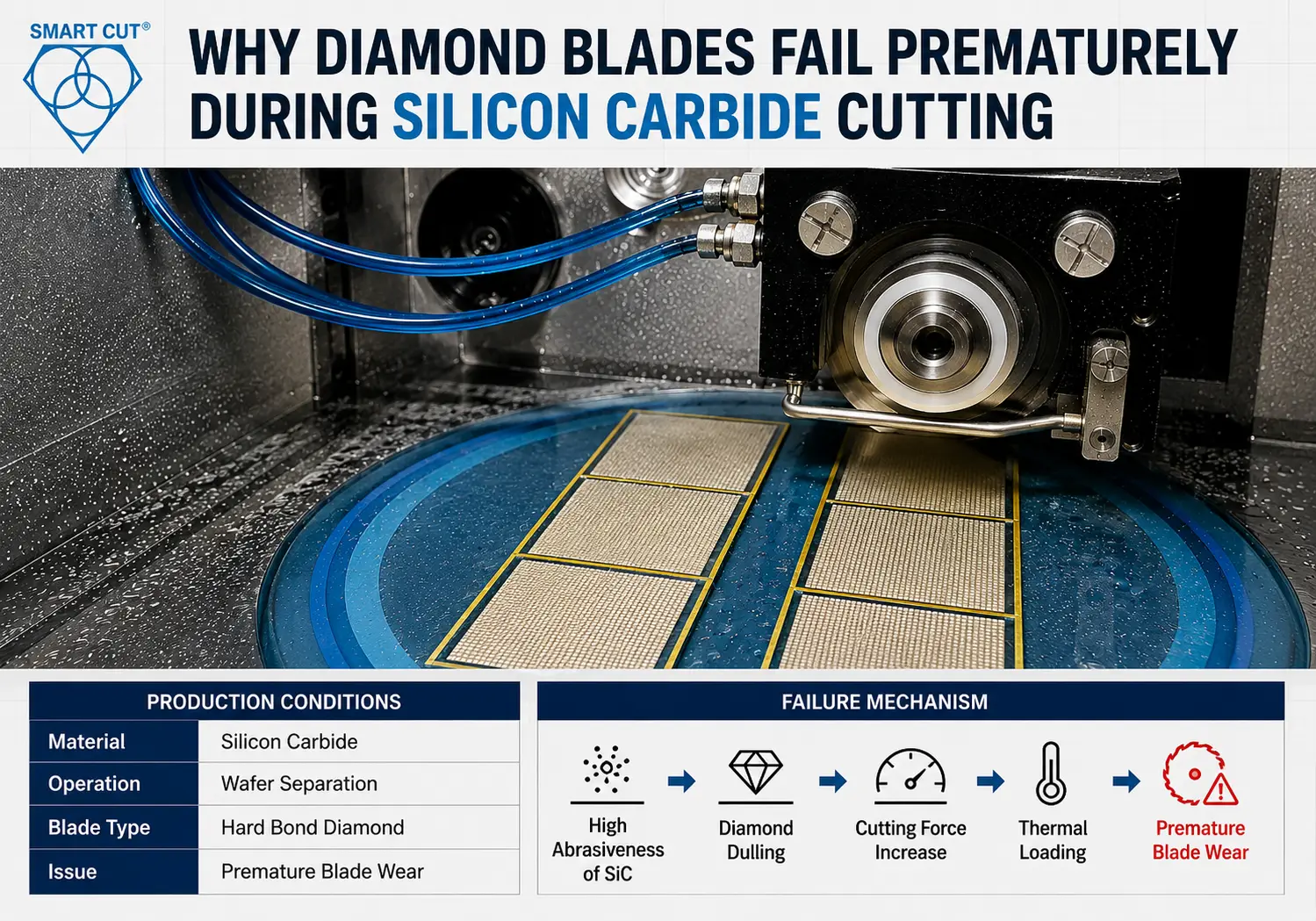
Table of Contents
Toggle
American Based Manufacturer

Established in 1990


Custom manufacturing


A manufacturer producing silicon carbide substrates for power electronics and semiconductor applications experienced severe diamond blade wear during precision slotting and wafer separation operations. Blade life dropped below acceptable production thresholds within weeks after transitioning from alumina-based ceramic components to silicon carbide. Operators reported increasing spindle load, thermal discoloration near cut edges, unstable kerf width, and excessive dressing frequency during long production runs.
The original cutting process used a hard bond sintered diamond blade previously qualified for alumina and ferrite materials. The blade maintained dimensional stability during softer ceramic cutting operations but failed rapidly on silicon carbide because the abrasive wear characteristics of SiC were significantly different. Blade exposure deteriorated quickly, cutting force increased progressively, and thermal stress amplified edge fracture near blade exit transitions.
Initial troubleshooting attempts focused on reducing spindle RPM and increasing coolant flow. Neither approach stabilized blade life because the root cause remained unchanged. The blade bond structure was too hard for the abrasive behavior of silicon carbide. Once abrasive exposure decreased, cutting pressure increased sharply and accelerated thermal degradation.
A revised process qualification program evaluated bond structure, diamond concentration, coolant penetration, spindle load trends, and dressing intervals. The optimized process used a softer bond diamond blade with revised feed parameters and controlled dressing intervals. Blade life increased substantially while reducing edge cracking and stabilizing production throughput
Customer Application and Production Environment
The silicon carbide components were used in semiconductor wafer processing and power electronic packaging applications requiring tight dimensional control and low edge damage. The process involved precision slotting and wafer singulation on brittle SiC substrates ranging from 0.5 mm to 3 mm thickness. UKAM’s precision wafer dicing solutions address exactly these requirements.
Original Production Conditions
|
Parameter |
Original Production Setup |
|---|---|
|
Material |
Silicon carbide |
|
Industry |
Semiconductor and power electronics |
|
Machine type |
Precision dicing saw |
|
Blade type |
Hard bond sintered diamond |
|
Coolant system |
Flood coolant |
|
Operation |
Wafer separation and slotting |
|
Kerf tolerance |
±0.02 mm |
|
Surface finish target |
Ra below 0.20 µm |
|
Primary issue |
Premature blade wear |
|
Scrap rate |
6.8% |
The process operated continuously across multiple shifts. Blade wear accelerated significantly after extended production cycles because abrasive exposure became unstable and spindle load increased progressively.
Typical Blade Specifications for Silicon Carbide Cutting

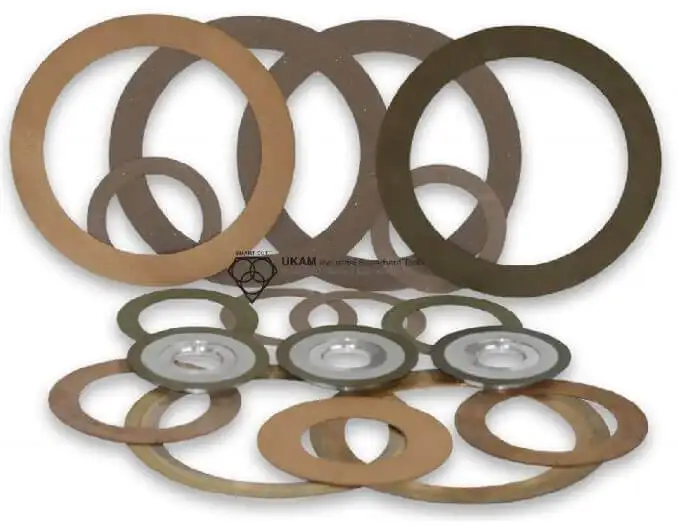
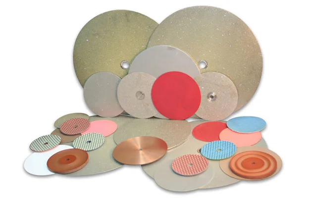
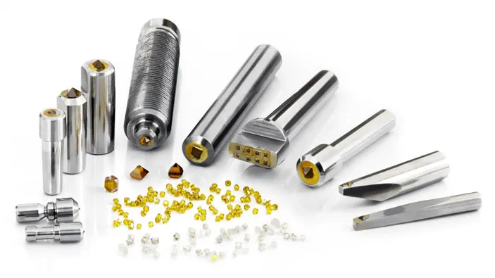
While exact blade specifications vary depending on substrate geometry, machine configuration, and production requirements, the following characteristics are commonly used. Explore UKAM’s ultra-thin precision diamond blades for a full range of available geometries.
|
Parameter |
Typical Range |
|---|---|
|
Blade Outside Diameter (OD) |
4"-8" |
|
Kerf Thickness |
0.010"-0.040" |
|
Arbor Size |
1/2" - 1.25" |
|
Bond Type |
Soft Bond, Resin Bond, Hybrid Bond |
|
Diamond Grit Size |
Fine to Medium |
|
Diamond Concentration |
25 – 200 |
|
Diamond Depth |
Application Dependent |
|
Blade Configuration |
Continuous Rim, Wafering, Dicing |
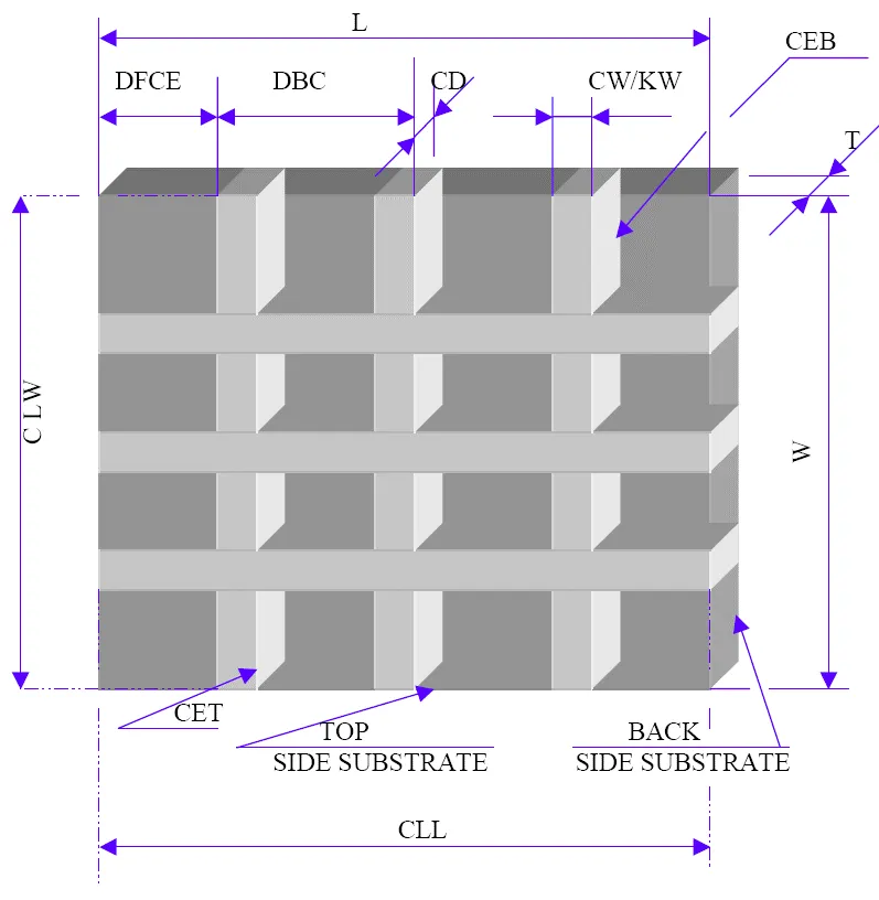
Note: Actual blade specifications vary based on silicon carbide thickness, cut depth, machine rigidity, production volume, and required edge quality. Understanding blade geometry is critical because blade diameter, kerf thickness, bond structure, and diamond concentration all directly influence blade life, spindle load, thermal stability, and process economics.
Why Silicon Carbide Causes Severe Blade Wear
Silicon carbide behaves differently than alumina, sapphire, ferrite, or fused silica during cutting operations. SiC combines high hardness with aggressive abrasive behavior. The material continuously wears the bond matrix surrounding the diamond particles while simultaneously generating high localized cutting force. This is why advanced ceramic cutting solutions must be matched precisely to each substrate material.
Material Behavior Comparison
|
Material |
Relative Hardness |
Abrasiveness |
Primary Failure Mode |
|---|---|---|---|
|
Silicon Carbide |
Very high |
Very high |
Premature blade wear |
|
Alumina |
High |
Moderate |
Edge chipping |
|
Silicon Nitride |
High |
Moderate |
Corner fracture |
|
Sapphire |
Very high |
Low |
Subsurface cracking |
|
Fused Silica |
Moderate |
Low |
Thermal edge breakout |
|
Ferrite |
Moderate |
Moderate |
Kerf Stability |
The original hard bond blade retained diamond particles too aggressively. Once the exposed diamond dulled, cutting pressure increased rapidly because fresh abrasive particles were not exposed efficiently. Compare blade behaviors across UKAM’s advanced ceramic cutting solutions.
Baseline Documentation Before Process Changes
The engineering team recorded production data before modifying the process. Simultaneous parameter changes prevent accurate root-cause analysis during blade qualification. UKAM’s knowledge center provides additional guidance on establishing proper process baselines.
|
Parameter |
Measurement Method |
Unit |
Notes |
|---|---|---|---|
|
Material grade |
Incoming inspection |
SiC type |
Verify substrate specification |
|
Blade specification |
Supplier documentation |
Bond and grit |
Confirm concentration |
|
Blade diameter |
Caliper verification |
mm |
Measure actual OD |
|
Spindle speed |
Tachometer |
RPM |
Verify loaded RPM |
|
Surface speed |
Calculated |
SFM |
Primary cutting parameter |
|
Feed rate |
CNC verification |
mm/min |
Record actual feed |
|
Coolant flow |
Flow meter at nozzle |
L/min |
Do not measure at pump |
|
Coolant pressure |
Inline gauge |
PSI |
Verify during cutting |
|
Dressing interval |
Production log |
Cuts per dress |
Record by shift |
|
Spindle load |
Machine monitoring |
% load |
Track continuously |
|
Kerf width |
Optical comparator |
mm |
Monitor blade wear |
|
Scrap rate |
Inspection report |
% rejected parts |
Primary KPI |
The process review identified two major trends. Spindle load increased sharply after approximately 25 cuts, and coolant penetration into the blade-workpiece interface decreased during deep slotting operations.
Existing Blade Performance Problems
The original sintered metal bond blade delivered acceptable dimensional control during short production runs but failed rapidly under continuous silicon carbide processing conditions.
|
Observation |
Root Cause |
|---|---|
|
Rapid spindle load increase |
Dull abrasive exposure |
|
Thermal discoloration |
Excess cutting force |
|
Frequent dressing requirements |
Incorrect bond hardness |
|
Kerf widening |
Bond degradation |
|
Blade vibration |
Uneven abrasive exposure |
|
Edge cracking |
Thermal stress concentration |
Operators attempted to compensate by increasing feed pressure, which accelerated thermal loading and bond wear.
Cost Per Part Analysis: Conventional vs Optimized Blade
Blade price alone does not determine process economics. Dressing frequency, spindle stability, scrap rate, and production throughput strongly affect actual manufacturing cost. Contact UKAM’s engineering team for a detailed cost-per-part analysis tailored to your specific application.
|
Parameter |
Conventional Hard Bond Blade |
Optimized Soft Bond Blade |
|---|---|---|
|
Blade price |
$540 |
$690 |
|
Components processed per blade |
420 |
1,050 |
|
Dressing interval |
Every 18 cuts |
Every 55 cuts |
|
Average cycle time |
6.1 min |
4.9 min |
|
Scrap rate |
6.8% |
2.3% |
|
Average spindle load stability |
Variable |
Stable |
|
Cost per component from blade cost |
$1.29 |
$0.66 |
|
Estimated scrap loss per 1,000 parts |
$7,480 |
$2,530 |
|
Estimated savings per 1,000 parts |
Baseline |
Approx. $6,200 |
The values shown are illustrative examples based on representative silicon carbide cutting applications. Actual blade pricing, tooling costs, productivity, and savings will vary. The majority of savings came from improved blade stability and reduced production downtime rather than blade purchase price alone.
Blade Variables Affecting Silicon Carbide Cutting Performance
Silicon carbide is significantly more abrasive than alumina, ferrite, fused silica, and many other advanced materials processed at UKAM’s advanced ceramics division. As a result, blade geometry and abrasive exposure play a critical role in process stability.
Blade Diameter (OD)
Larger diameter blades generally provide greater rigidity and improved straightness during deep cutting operations. However, larger diameters also increase spindle load and may require more aggressive coolant delivery. Browse UKAM’s full range of ultra-thin precision diamond blades to match blade OD to your specific machine configuration.
Kerf Thickness
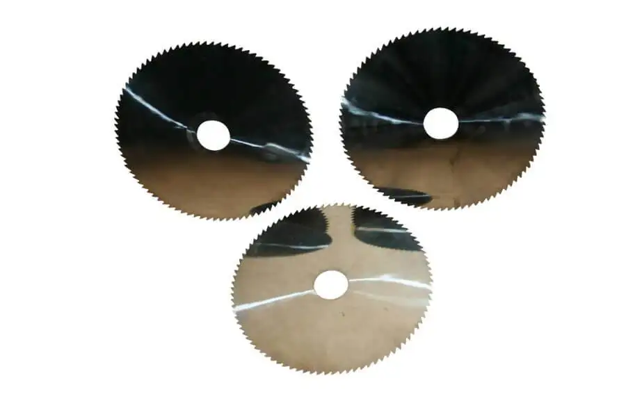
Kerf thickness influences both material removal rate and cutting force. Thicker blades provide additional stability but increase cutting resistance. Diamond dicing blades are available in a wide range of kerf thicknesses for both rough and finish operations.
Diamond Concentration
Diamond concentration affects blade wear characteristics and cutting efficiency. Higher concentrations generally improve blade life but can increase cutting force if abrasive exposure becomes unstable.
Diamond Grit Size
Coarser grit sizes typically improve material removal rates, while finer grit sizes improve surface finish and edge quality. UKAM’s custom diamond tool manufacturing program allows grit size to be specified precisely for each substrate type.
Bond Structure
Bond structure is one of the most important variables affecting silicon carbide cutting performance. Softer bond systems, including resin bond and hybrid bond configurations, often provide more stable self-sharpening behavior during extended production runs.
Blade Qualification Trials
Proper arbor selection helps minimize vibration and maintain kerf consistency. Poor blade mounting can amplify cutting force fluctuations and accelerate premature blade wear.
Arbor Size and Machine Stability
Proper arbor selection helps minimize vibration and maintain kerf consistency. Poor blade mounting can amplify cutting force fluctuations and accelerate premature blade wear.
Blade Qualification Trials
The engineering group evaluated multiple blade specifications during qualification testing.
|
Blade |
Bond Type |
Grit Size |
Result |
|---|---|---|---|
|
Blade A |
Hard sintered bond |
Medium |
Long retention, unstable cutting force |
|
Blade B |
Standard soft bond |
Medium |
Improved wear behavior and lower spindle load |
|
Blade C |
Soft bond, lower concentration |
Fine |
Best spindle stability, blade life, and thermal control |
The qualification process demonstrated that bond behavior and abrasive exposure had a greater influence on blade life than spindle RPM adjustments alone. Explore UKAM’s diamond dicing blades for precision wafer applications.
Why RPM Reduction Alone Failed

The production team initially attempted to stabilize blade life by reducing spindle RPM while maintaining the original hard bond sintered blade specification. The approach reduced heat generation slightly but did not stabilize abrasive exposure.
|
Attempted Correction |
Result |
Why It Failed |
|---|---|---|
|
Lower spindle RPM |
Minor improvement |
Abrasive exposure remained unstable |
|
Increased coolant flow |
Moderate improvement |
Blade loading continued |
|
Reduced feed pressure |
Better edge quality |
Throughput loss unacceptable |
|
More frequent dressing |
Improved stability |
Blade specification still incorrect |
|
Softer bond blade |
Major improvement |
Stable self-sharpening behavior |
Technical Explanation: Why the Softer Bond Worked
The optimized blade used a softer bond matrix designed to release worn diamond particles more consistently during silicon carbide cutting. This controlled self-sharpening mechanism — a core principle behind UKAM’s SMART CUT® technology — stabilized cutting force and reduced thermal loading. Fresh abrasive exposure remained more consistent throughout long production runs.
|
Parameter |
Hard Bond Blade |
Soft Bond Blade |
|---|---|---|
|
Diamond retention |
Very high |
Controlled |
|
Self sharpening |
Limited |
Stable |
|
Thermal loading |
Higher |
Lower |
|
Spindle load variation |
High |
Reduced |
|
Dressing frequency |
Frequent |
Lower |
|
Dressing frequency |
Variable |
More stable |
Silicon carbide behaves as a highly abrasive material. Bond structures optimized for abrasive resistance alone usually generate unstable cutting conditions. See UKAM’s resin bond diamond blades for complementary material applications.
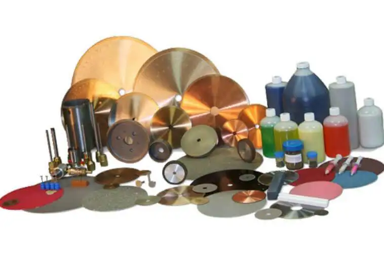
Coolant Delivery Optimization
The original coolant system delivered sufficient overall volume but failed to penetrate consistently into the cutting interface during deep slotting operations. The revised setup repositioned nozzles and increased pressure stability.Different advanced materials require different bond behavior and abrasive exposure characteristics. View UKAM’s full advanced ceramic cutting solutions for material-specific guidance.
|
Coolant Parameter |
Original Setup |
Optimized Setup |
|---|---|---|
|
Delivery type |
Flood coolant |
Directed nozzle flow |
|
Pressure stability |
Variable |
Stable |
|
Interface penetration |
Moderate |
Improved |
|
Debris evacuation |
Inconsistent |
Stable |
|
Thermal edge damage |
Frequent |
Reduced |
For sapphire cutting applications, explore UKAM’s photonics and sapphire cutting solutions. For general precision grinding, see UKAM’s precision diamond and CBN grinding wheels.
Material-Specific Blade Recommendations
Different advanced materials require different bond behavior and abrasive exposure characteristics. View UKAM’s full advanced ceramic cutting solutions for material-specific guidance.
|
Material |
Recommended Bond Type |
Failure Mode to Watch |
|---|---|---|
|
Silicon Carbide |
Premature blade wear |
|
|
Alumina |
Edge breakout |
|
|
Silicon Nitride |
Fine grit resin bond |
Corner fracture |
|
Sapphire |
Fine resin bond |
Subsurface cracking |
|
Tungsten Carbide |
Medium metal bond |
Thermal loading |
|
Quartz |
Thermal shock |
|
|
PCD materials |
Diamond pullout |
For sapphire cutting applications, explore UKAM’s photonics and sapphire cutting solutions. For general precision grinding, see UKAM’s precision diamond and CBN grinding wheels.
SMART CUT® Process Comparison
|
Parameter |
Conventional Hard Bond Blade |
SMART CUT® Soft Bond Blade |
|---|---|---|
|
Cutting force |
Higher |
Lower |
|
Thermal loading |
Higher |
Reduced |
|
Self sharpening behavior |
Moderate |
Controlled |
|
Dressing frequency |
Frequent |
Reduced |
|
Spindle load stability |
Variable |
More stable |
|
Blade wear consistency |
Unstable |
Improved |
|
Scrap rate stability |
Variable |
More repeatable |
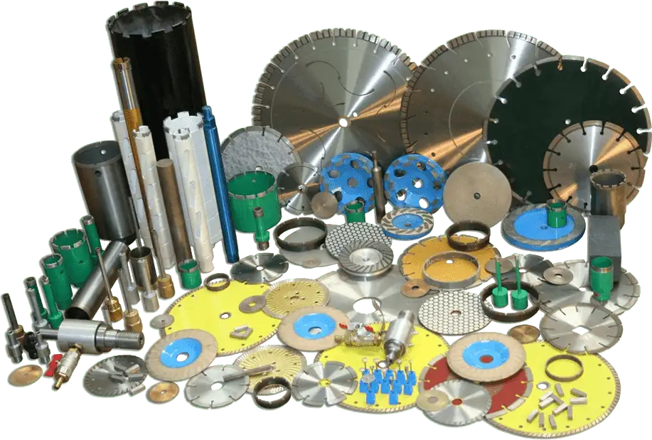
Explore UKAM’s silicon carbide cutting blades and diamond core drills for complete tooling solutions.
Qualification Checklist

Machine Condition
- Verify spindle runout below 0.0002 inches
- Confirm machine rigidity during deep slotting
- Inspect spindle bearing condition
- Verify spindle speed stability
Coolant System
- Measure coolant flow at cutting interface
- Verify coolant pressure consistency
- Inspect nozzle positioning
- Check filtration system condition
Blade Qualification
- Verify blade balance certification
- Confirm grit size and concentration — reference UKAM’s dicing blade specifications
- Record spindle load trends
- Validate dressing interval consistency
Process Parameters
- Record rough and finish feed rates separately
- Track kerf width variation
- Monitor thermal discoloration
- Record scrap rate by shift
Frequently Asked Questions
The hard sintered bond retained worn diamond particles too aggressively. Once abrasive exposure deteriorated, cutting force increased sharply and accelerated thermal loading. Silicon carbide requires controlled self-sharpening behavior.
Lower spindle speed reduced heat generation slightly but did not correct the underlying abrasive exposure problem. The bond structure still prevented efficient release of worn abrasive particles.
Spindle load trends revealed blade loading long before visible edge damage appeared. Stable spindle load usually indicates stable abrasive exposure and thermal behavior.
Flood coolant volume alone does not determine thermal stability. Coolant must penetrate consistently into the cutting interface to evacuate heat and debris effectively during deep slotting operations.
The largest improvement resulted from stabilizing cutting force throughout the cutting process. Proper bond selection, improved coolant penetration, controlled dressing intervals, and reduced vibration collectively minimized fracture propagation and significantly improved yield.
The largest improvement resulted from stabilizing cutting force throughout the cutting process. Proper bond selection, improved coolant penetration, controlled dressing intervals, and reduced vibration collectively minimized fracture propagation and significantly improved yield.
Key Engineering Principles
- Silicon carbide generates significantly higher abrasive wear than alumina or ferrite materials.
- Premature blade failure is primarily a bond behavior and abrasive exposure problem.
- Controlled self-sharpening stabilizes cutting force and thermal loading — see SMART CUT® technology.
- Coolant penetration at the cutting interface affects blade stability directly.
- Dressing frequency should be determined by spindle load trends rather than visual inspection alone.
- Spindle load monitoring provides early warning of blade instability.
- Stable silicon carbide cutting requires balancing bond structure, coolant delivery, machine rigidity, and feed pressure together.
- Scrap reduction often produces greater savings than maximizing blade retention alone.
- Different advanced materials require different bond optimization strategies.
- Blade qualification should be validated separately for each substrate material and thickness range.
Trusted by Tens of Thousands of Manufacturers, Laboratories,
Research Institutions Worldwide Since 1990
American Based Manufacturer
Established in 1990
Custom manufacturing
RELATED ARTICLES


