








































Precision Diamond Saw Pre-Operation Checklist

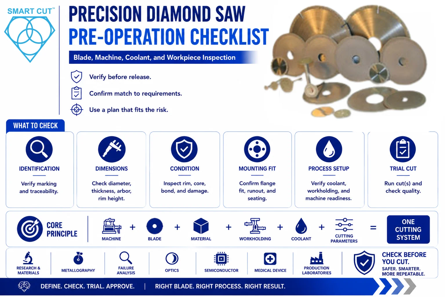
Table of Contents
ToggleMany precision cutting problems begin before the first cut. A suitable diamond blade may be mounted incorrectly. A clean machine may still have a clearance problem. Coolant may be present in the reservoir but fail to reach the cutting interface. A specimen may appear secure but move when cutting force is applied.
These conditions can contribute to chipping, cracking, blade wandering, thermal damage, excessive or inconsistent kerf, dimensional variation, poor surface condition, premature blade wear, and specimen loss.
A pre-operation inspection is therefore both a safety check and a process-control step. It confirms that the machine, blade, coolant, workpiece, workholding, and approved cutting parameters are suitable for the planned operation.
Core principle
Machine + Blade + Material + Workholding + Coolant + Cutting Parameters = One Cutting System
A problem in one part of this system can appear to be a problem somewhere else. Poor workholding can look like blade wandering. Inadequate coolant delivery can look like an unsuitable blade. Increasing feed force or feed rate to compensate for a loaded blade can increase edge damage and cutting instability.
For research, materials, metallography, failure-analysis, optics, semiconductor, medical-device, and production laboratories, a documented pre-operation check also improves repeatability between operators and specimens.
Trusted by Tens of Thousands of Manufacturers, Laboratories Research Institutions Worldwide Since 1990

American Based Manufacturer

Established in 1990


Custom manufacturing


What Should Be Checked Before Starting a Precision Diamond Saw?
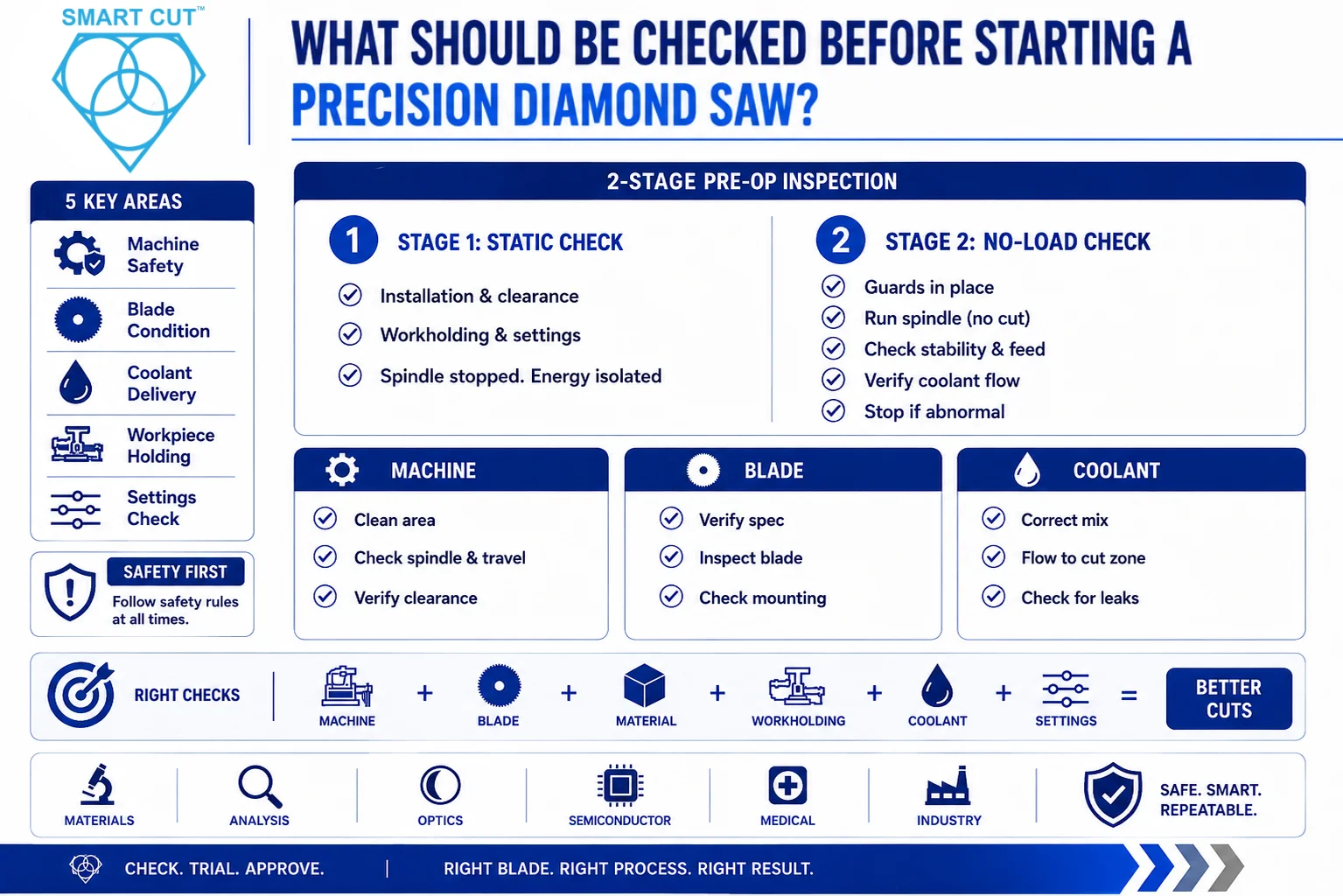
A complete check should cover five areas:
- Machine condition and safety provisions
- Diamond blade specification, condition, and installation
- Coolant condition and delivery
- Workpiece identification and workholding
- Approved cutting parameters and actual machine settings
Important safety limitation
This checklist does not replace the machine manual, laboratory SOP, hazard assessment, required training, PPE requirements, or facility energy-control procedure. Follow the machine manufacturer's instructions and your organization's safety requirements at all times.
Use a Two-Stage Pre-Operation Inspection
The inspection should be divided into a static pre-start check and a guarded no-load function check. This keeps physical setup work separate from checks that require the machine to operate.
Stage 1: Static Inspection Before Energizing the Spindle
Complete blade installation, physical inspection, clearance verification, workholding, and parameter review while the spindle is stopped. Control electrical, pneumatic, hydraulic, gravitational, or other stored energy as required by the machine manual and the facility’s energy-control procedure.
In U.S. workplaces, OSHA’s machine-guarding requirements address hazards from points of operation, rotating parts, and flying material.
Where setup or servicing can expose an employee to unexpected startup or stored energy, follow the applicable hazardous-energy control procedure.
Stage 2: Guarded No-Load Function Check
Restore energy only after the static inspection passes, the cutting area is clear, the workpiece and fixture are secure, and required guards are in position. Perform the function check according to the machine manual.
- Confirm that required guards, covers, interlocks, and safety devices are in their operating positions.
- Start the spindle without bringing the blade into the workpiece.
- Listen and observe for abnormal noise, vibration, movement, or visible instability.
- Verify smooth feed-system travel within the intended range.
- Verify coolant pump operation and delivery to the blade/workpiece interface, where the approved process uses coolant.
- Stop the machine and place it on hold if any abnormal condition is observed.
Machine Condition
The machine must be mechanically ready to perform a controlled cut.
Clean the Cutting Area
Remove debris from the worktable, stage, fixture area, splash area, and intended blade path. Residue from previous operations can affect fixture seating, specimen alignment, blade clearance, stage movement, coolant return, and measurement accuracy.
Check Mechanical Condition and Travel
Inspect the spindle, feed mechanism, stage, vise, fixture, micrometer, and relevant motion components for damage, looseness, excessive play, or contamination. During the guarded no-load function check, investigate abnormal noise or vibration instead of attempting to compensate by changing RPM, feed rate, or cutting depth.
Where the qualified process specifies a runout limit, measure spindle or blade runout using the approved method and calibrated equipment. Never attempt a manual measurement against a rotating blade.
Verify Blade Clearance and Guarding
Confirm adequate clearance throughout the intended blade and feed travel. The blade must not contact the fixture, worktable, coolant nozzle, guard, or any unintended machine component. Required guarding must be secured before the spindle operates.
Review UKAM’s range of precision cutting saws when selecting a machine for a new sectioning requirement.
Diamond Blade Condition and Installation
Correct blade selection does not guarantee correct performance. The blade must also be undamaged, compatible with the saw, and installed according to the machine and blade manufacturer’s requirements.
Verify the Blade Specification
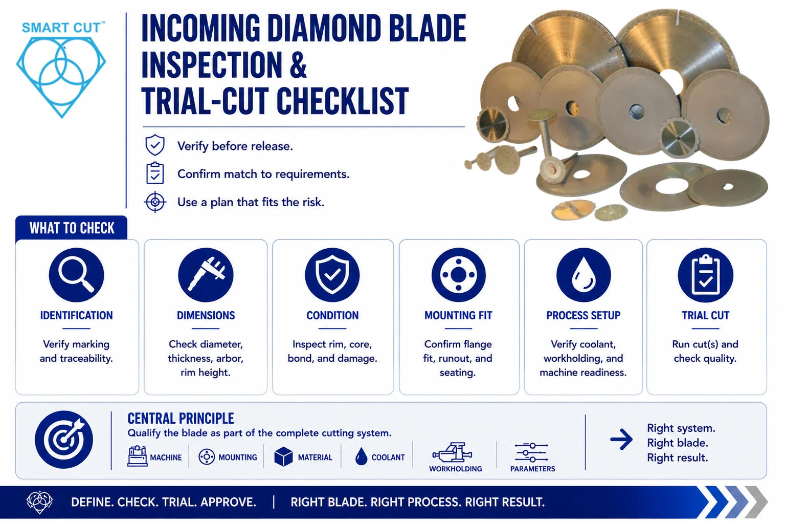
Confirm the blade against the approved procedure or validated application. Relevant information may include:
- Manufacturer and part number
- Blade type and construction
- Outside diameter and arbor size
- Diamond cutting-edge thickness
- Expected kerf width, where specified
- Diamond mesh or particle size
- Bond type and bond specification
- Maximum permitted operating speed
- Lot, batch, or serial information where traceability is required
Blade thickness and kerf width are different measurements
Diamond cutting-edge thickness is the physical thickness measured on the blade. Kerf width is the width of the cut produced under defined cutting conditions. The kerf may be wider than the measured cutting edge because of blade motion, runout, material response, coolant conditions, and other process factors.
For additional selection guidance, review diamond mesh size, diamond bond types, and UKAM’s precision diamond blade selection resources.
Inspect the Blade and Mounting Components
Inspect the blade, arbor, flanges, mounting surfaces, and hardware before installation. Look for:
- Cracks, edge damage, deformation, or other visible damage
- Excessive wear or loss of the cutting edge
- Loading, contamination, corrosion, or foreign material
- Damage or contamination on mounting surfaces
- Incorrect, damaged, or loose mounting hardware
Information about loading, bond behavior, and wear is available in UKAM’s guide to diamond tool bond hardness and wear resistance.
Verify Installation
- The arbor size and blade mounting geometry match the machine.
- The blade and flanges are clean and seated correctly.
- Mounting hardware is tightened using the approved method and specified torque, where applicable.
- Rotation direction is correct where the blade has a directional requirement.
- The selected spindle speed does not exceed the blade or machine limit.
- The installed blade has adequate clearance throughout the intended travel.
Coolant System Inspection
Coolant must do more than fill the reservoir. It must reach the cutting interface with the condition, concentration, direction, and flow required by the approved process.
Check Coolant Condition
- Confirm the approved coolant type and concentration.
- Check the reservoir level.
- Inspect for contamination, odor, deterioration, or excessive accumulated debris.
- Verify filtration and maintenance status where applicable.
- Check hoses, fittings, drains, and the work area for leaks.
- Confirm coolant compatibility with the workpiece, coating, fixture, and machine.
Check Coolant Delivery
During the guarded no-load function check, confirm pump operation, nozzle position, flow, filtration, and actual delivery to the blade/workpiece interface. A full reservoir does not demonstrate adequate delivery.
A displaced nozzle, restricted line, blocked filter, low pump output, or poor return path can reduce cooling and debris removal. This is especially important for heat-sensitive materials and applications where thermal damage may not become visible until after sectioning.
For more detail, review UKAM’s coolant flow guide.
Workpiece and Workholding Inspection
Verify the Workpiece
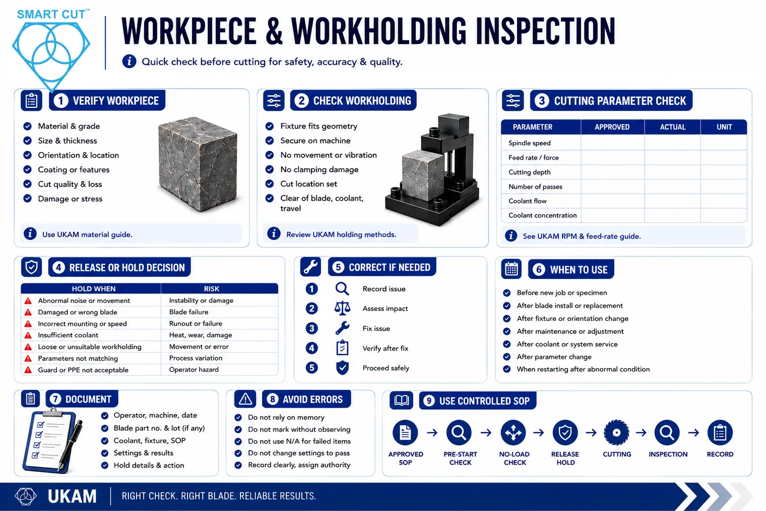
Confirm the correct specimen and relevant application information before mounting:
- Material and material grade
- Dimensions and thickness
- Orientation and required cut location
- Coating, surface treatment, or sensitive features
- Required cut quality and allowable material loss
- Any contamination, damage, internal stress, or geometry that can affect cutting
Use the UKAM material guide when developing a process for a new material.
Check Workholding
The specimen must remain supported and secure throughout the cut without unnecessary clamping stress. This is particularly important for brittle, thin, irregular, layered, coated, or high-value specimens.
- The fixture is appropriate for the specimen geometry.
- The fixture is securely mounted to the machine.
- The specimen cannot shift, rotate, lift, or vibrate under the expected cutting force.
- Clamping does not crack, deform, or preload a fragile specimen.
- The intended cut location is clearly established.
- Fixture components remain clear of the blade, coolant nozzle, and machine travel.
Review UKAM’s material holding methods for additional fixture and support considerations.
Cutting Parameter Verification
The checklist should verify an established process. It should not create universal RPM, feed, or coolant values. Approved settings should come from the laboratory’s qualified procedure, the machine and blade recommendations, or application-specific testing.
Record both the approved value and the actual setting. This provides better traceability when an unexpected cutting result is investigated.
| Parameter | Approved Value | Actual Setting | Unit |
|---|---|---|---|
| Spindle speed | |||
| Feed rate or feed force | |||
| Cutting depth | |||
| Number of passes | |||
| Coolant flow | |||
| Coolant concentration |
For application-specific calculation guidance, review UKAM’s RPM and feed-rate guide.
Make a Clear Release or Hold Decision
The inspection should end with one practical decision: Is the complete cutting setup ready to make the planned cut?
| Place the operation on hold when | Potential consequence |
|---|---|
| Abnormal spindle noise, vibration, or movement | Blade instability, poor cut quality, or machine damage |
| Damaged or incorrectly specified blade | Blade failure, excessive wear, or specimen damage |
| Incorrect mounting, arbor fit, rotation, or speed | Runout, instability, uneven wear, or failure |
| Insufficient coolant delivery | Heat, loading, wear, cracking, or surface damage |
| Loose or unsuitable workholding | Specimen movement, chipping, cracking, or dimensional error |
| Approved and actual parameters do not match | Uncontrolled process variation |
| Guard, interlock, safety device, or required PPE is not acceptable | Operator exposure to an uncontrolled hazard |
Correct the Failed Condition Before Cutting
- Identify the failed condition. Record what was found instead of marking the item only as failed.
- Evaluate its significance. Determine whether it affects operator safety, machine condition, blade integrity, workpiece security, coolant delivery, required cut quality, or compliance with the approved procedure.
- Correct the condition. Replace or reinstall the blade, restore coolant flow, secure the workpiece, correct the setting, remove contamination, or address the machine abnormality as appropriate.
- Recheck the setup. Verify the failed item again after corrective action.
- Release or continue the hold. Proceed only after the applicable requirements are satisfied and the authorized person has released the operation.
When and How Often Should the Checklist Be Used?
The laboratory’s SOP and quality system should define the required frequency. Common trigger points include:
- Before a new cutting job or new specimen
- After blade installation or replacement
- After changing the fixture, workholding method, or cut orientation
- After machine maintenance or adjustment
- After coolant replacement, filtration work, or coolant-system maintenance
- After approved cutting parameters change
- When restarting after an abnormal condition or interrupted process
The objective is not to create unnecessary paperwork. It is to prevent a change in the cutting setup from going unnoticed and to preserve enough process history to investigate variation between specimens.
Document Results for Traceability
A checklist records enough information to reconstruct the setup without turning the form into a second SOP. Identify the operator, machine, specimen, blade part number, blade lot when applicable, coolant, fixture, approved procedure revision, and date. Record actual settings rather than relying on a pass mark. If the operation is placed on hold, describe the failed condition and the action taken.
Traceability is valuable when a cut later shows unexpected chipping, taper, surface damage, dimensional error, or excessive material loss. The record helps determine whether the result occurred under the approved setup and whether the condition affected one specimen, one blade lot, one machine, or a larger group of work.
Avoid Common Checklist Errors
Several habits reduce the value of a pre-operation check. Do not complete the form from memory after cutting. Do not mark items as acceptable without observing the applicable condition. Do not treat not applicable as a convenient substitute for a failed item. Do not change RPM, feed, coolant, or blade selection merely to make the checklist pass. Any change to an approved process should follow the laboratory’s change-control and qualification requirements.
- Use clear acceptance criteria. Terms such as clean, secure, and adequate should refer to the machine manual, controlled procedure, or qualified process.
- Record objective values where they matter. Examples include spindle speed, coolant concentration, runout, blade identification, and fixture location.
- Assign authority for release. The checklist should state who may clear a hold condition and when reinspection is required.
- Preserve the completed record for the period established by the laboratory’s quality system and customer, regulatory, or contractual requirements.
Review the form periodically. Repeated hold conditions can identify maintenance needs, unclear instructions, training gaps, unsuitable fixtures, or process limits that should be addressed through improvement and review.
Use the Checklist With the Laboratory’s Controlled SOP
The SOP defines the approved process. The checklist confirms that the conditions required to execute that process are present before cutting begins. Used together, they create a controlled sequence:
Controlled workflow
Approved SOP > Static Pre-Start Inspection > Guarded No-Load Check > Release or Hold > Cutting > Inspection > Record
For guidance on developing the controlled procedure, review How to Write a Precision Diamond Saw SOP.
Frequently Asked Questions
It verifies that the machine, blade, coolant, workpiece, workholding, safety provisions, and approved cutting parameters are ready before the cutting operation is released.
No. The SOP defines the approved process. The checklist verifies that the required conditions and settings are present before cutting.
Complete the static inspection first. Start the spindle only for the guarded no-load function check after the setup is secure, required guards are in position, and the machine manual permits the check.
No. Cutting-edge thickness is a physical blade measurement. Kerf width is the width of the cut produced under defined process conditions.
No. The checklist should compare actual settings with application-specific approved values.
Yes, as a framework. The laboratory should adapt the requirements to the machine, blade, material, specimen geometry, workholding, coolant, and required cut quality.
Precision diamond sawing begins before the spindle starts. A controlled pre-operation inspection verifies that the machine is mechanically ready, the correct blade is installed and undamaged, coolant can reach the cutting interface, the specimen is properly supported, and actual settings match the approved process.
These checks help prevent avoidable blade damage, specimen damage, thermal problems, dimensional variation, and inconsistent sectioning. They also provide useful process history when a cut or specimen later fails inspection.
For application-specific blade, machine, workholding, coolant, or cutting-process recommendations, contact the UKAM applications engineering team.
RELATED ARTICLES


Careful sample preparation is the key to good metallographic analysis. Although equipment features and process conditions are significant factors, the impact
