








































Diamond Tool Selection and Qualification: How Engineers Match, Test, and Validate Tooling for Different Materials

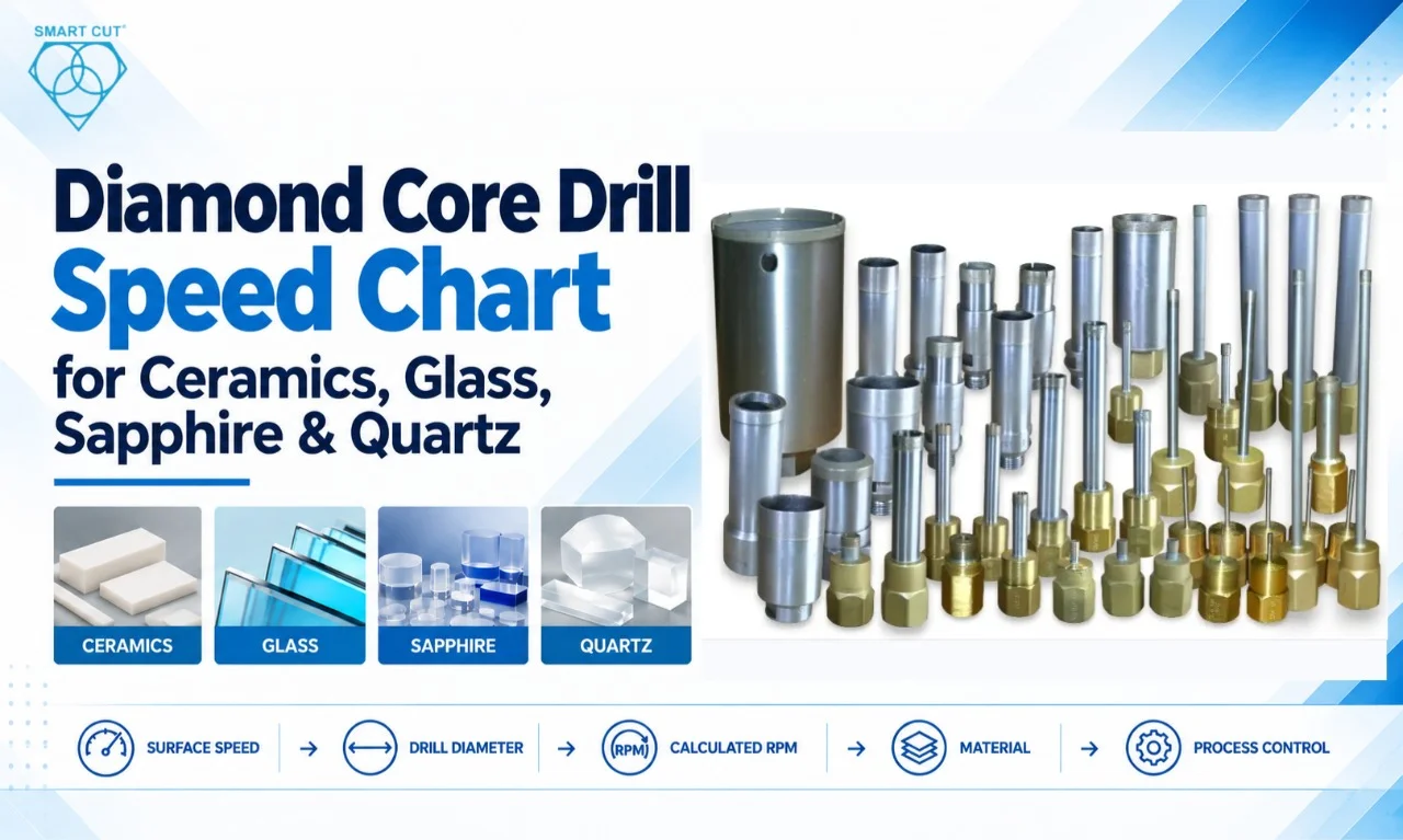
Table of Contents
Toggle
American Based Manufacturer

Established in 1990


Custom manufacturing


A diamond tool can be correctly specified on paper and still fail in production.
The problem may not be the diamond grit. It may be bond behavior, abrasive exposure, spindle runout, workpiece support, coolant delivery, breakthrough loading, tool geometry, or process conditions that are not suited to the application.
For engineers, diamond tool selection should therefore be treated as a qualification problem, not simply a purchasing decision.
The objective is to establish a controlled relationship between:
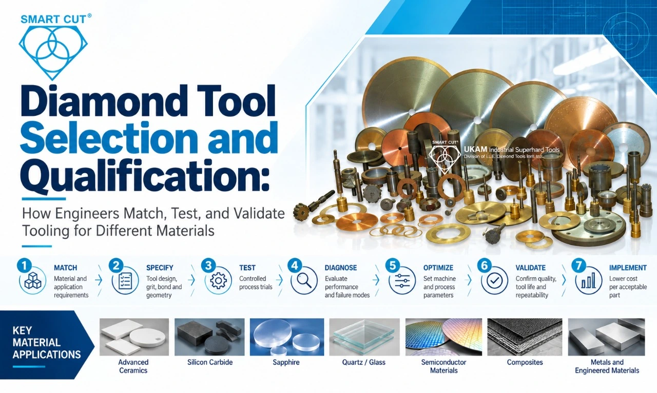
Material → Application → Failure Mode → Tool Specification → Machine → Process Parameters → Quality → Tool Life → Cost Per Acceptable Part
This approach is relevant to advanced ceramics, composites, semiconductor materials, glass, quartz, metals, optical materials, and other difficult-to-machine materials. UKAM’s Application Industry Guide covers materials including alumina, silicon carbide, sapphire, fused silica, zirconia, technical ceramics, composites, glass and quartz, semiconductor materials, and numerous engineered materials.
The purpose of this article is not to provide one universal diamond tool specification. It establishes an engineering method for selecting, testing, diagnosing, and validating diamond tooling for a specific material and production application.
Technical data note:
All numerical calculations, costs, tool life values, cycle times, scrap rates, and process parameters presented as examples in this article are illustrative only. They are not UKAM recommended operating conditions, product guarantees, supplier performance data, or actual UKAM pricing. Actual results depend on material grade, workpiece geometry, machine condition, tooling configuration, process conditions, and production requirements.
1. Tool Selection Is Not Tool Qualification
A supplier can recommend a diamond tool based on material and application. That recommendation still needs to be qualified against the actual manufacturing process.
Consider a ceramic drilling operation (see the core drill speed chart).
The tool may produce an acceptable hole during the first several parts. After additional production, spindle load may increase, hole size may change, or exit chipping may exceed the allowable limit.
Changing the diamond grit immediately may not solve the problem.
The actual mechanism could be:
- abrasive loading
- insufficient abrasive exposure
- bond wear
- excessive feed
- spindle runout
- inadequate workpiece support
- coolant delivery problems
- tool mounting error
- material variation
The visible failure is therefore not necessarily the root cause.
A controlled qualification process asks four questions:
- What result does the process require?
- What is currently limiting that result?
- Which tooling or process variable controls the failure mechanism?
- Can the improvement be reproduced under representative production conditions?
That distinction separates an engineering qualification from trial and error.
2. Start With Material, Application, and Failure Mode
UKAM’s application guide organizes materials and applications into broad groups such as advanced ceramics, composites, glass and quartz, semiconductor materials, optical and photonic materials, sample preparation, and other industrial materials.
An engineer should narrow that broad classification into the exact manufacturing problem.
Engineering Application Matrix
|
Input |
What should be documented? |
Why it matters |
|---|---|---|
|
Material |
Exact material and grade |
Materials within the same family can behave differently |
|
Material condition |
Heat treatment, coating, porosity, microstructure, laminate structure |
Changes fracture and cutting behavior |
|
Application |
Cutting, drilling, grinding, lapping, polishing, dicing, profiling |
Determines contact conditions |
|
Geometry |
Thickness, diameter, depth, feature size, profile |
Determines engagement and support |
|
Quality |
Tolerance, finish, edge condition, flatness |
Defines process acceptance |
|
Production volume |
Prototype, low volume, production |
Changes the importance of tool life and repeatability |
|
Machine |
Spindle, stiffness, runout, speed and feed capability |
Defines the available process window |
|
Coolant |
Type, flow, pressure, delivery |
Affects thermal conditions and debris removal |
|
Failure mode |
Chipping, cracking, loading, wear, finish deterioration |
Determines where to investigate first |
The better engineering question is not:
Which diamond tool is best for this material?
It is:
Which tooling configuration can consistently produce the required result on this material, geometry, machine, and production process?
3. Establish a Baseline Before Changing the Tool
A tooling trial should begin with documented production data.
Without a baseline, an engineer may change the tool and still be unable to determine whether the process actually improved.
Baseline Process Record
|
Production observation |
Possible mechanism |
Investigation priority |
|---|---|---|
|
Penetration rate decreases |
Diamond wear or loading |
Inspect abrasive layer |
|
Entry chipping increases |
Excessive mechanical loading |
Check feed and runout |
|
Exit breakout increases |
High breakthrough load |
Check final feed stage |
|
Cutting temperature increases |
Excessive cutting energy or poor cooling |
Check speed and coolant |
|
Hole diameter changes |
Tool wear or runout |
Inspect drill and spindle |
|
Hole becomes tapered |
Deflection or uneven wear |
Check rigidity |
|
Cutting becomes intermittent |
Poor abrasive exposure |
Review bond condition |
|
Tool life varies significantly |
Changing workpiece or process conditions |
Review baseline |
This baseline becomes the reference against which the new tooling configuration is judged.
4. Use Engineering Calculations Instead of RPM Alone
RPM is not sufficient for comparing rotating diamond tools with different diameters.
Peripheral Speed
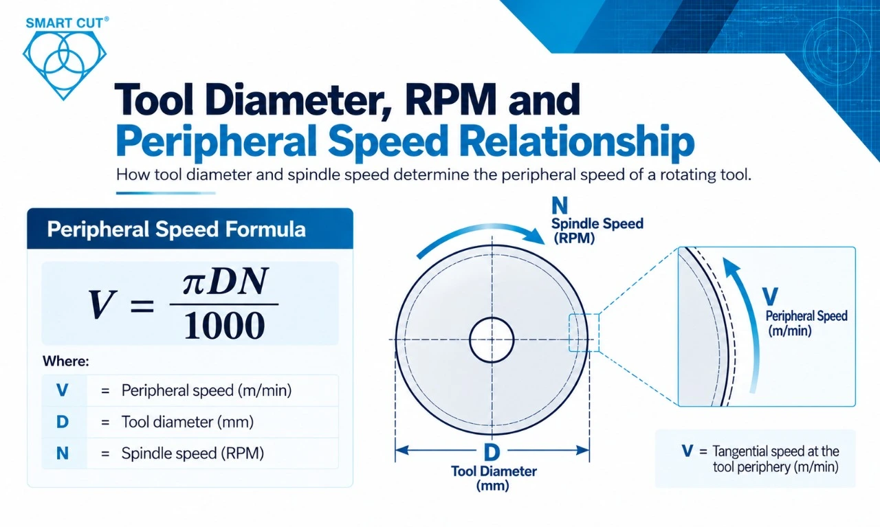
For a rotating tool:
Where:
- VV = peripheral speed in m/min
- DD = tool diameter in mm
- NN = spindle speed in RPM
For an illustrative 25 mm tool operating at 600 RPM:
This is an illustrative calculation only.
If tool diameter changes while RPM remains constant, peripheral speed changes. Two trials should therefore not be considered equivalent simply because both use the same RPM.
Feed Per Revolution
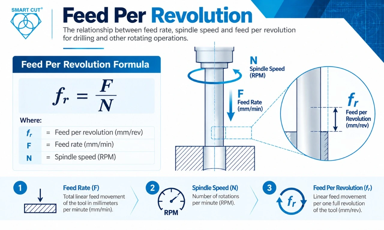
For drilling and other rotating operations:
Where:
- frfr = feed per revolution in mm/rev
- FF = feed rate in mm/min
- NN = spindle speed in RPM
For an illustrative feed rate of 60 mm/min at 600 RPM:
Again, this is an illustrative calculation, not a UKAM recommended process condition.
These calculations provide a consistent engineering basis for comparing process trials.
5. Diamond Tool Specification Is a System
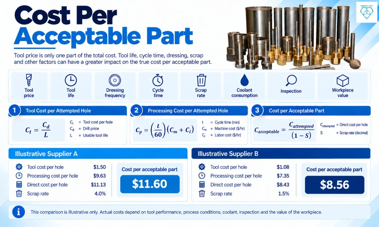
Diamond grit should not be selected independently from bond, concentration, geometry, machine condition, and process parameters.
Tool Specification Variables
|
Metric |
Illustrative Supplier A |
Illustrative Supplier B |
|---|---|---|
|
Drill price |
$180 |
$260 |
|
Usable tool life |
120 holes |
240 holes |
|
Dressing interval |
40 holes |
80 holes |
|
Cycle time |
5.5 min |
4.2 min |
|
Scrap rate |
4.0% |
1.5% |
|
Machine cost |
$60/hr |
$60/hr |
|
Labor cost |
$45/hr |
$45/hr |
|
Tool cost per attempted hole |
$1.50 |
$1.08 |
|
Machine and labor per attempted hole |
$9.63 |
$7.35 |
|
Direct cost per attempted hole |
$11.13 |
$8.43 |
|
Approximate cost per acceptable hole |
$11.60 |
$8.56 |
The specification should therefore be treated as a combination of variables, not a single grit number.
6. Bond and Abrasive Technology Selection
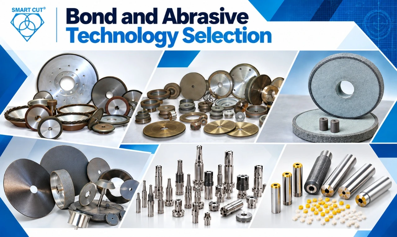
UKAM’s published technology portfolio includes sintered metal bond, resin bond, electroplated, brazed bond, hybrid bond, vitrified bond, PCD, CVD diamond, SMART CUT technology, diamond dressers, precision abrasives, consumables, and related equipment.
The engineering comparison should focus on how each technology behaves in the intended application.
Technology Comparison
|
Material |
Grit consideration |
Bond consideration |
Primary risk |
|---|---|---|---|
|
Alumina |
Fine to medium depending on quality requirement |
Controlled abrasive exposure |
Edge chipping |
|
Silicon nitride |
Application specific |
Stable cutting action |
Thermal damage |
|
Silicon carbide |
Application specific |
Strong wear resistance |
Diamond wear |
|
Sapphire |
Fine grit where edge quality dominates |
Controlled abrasive release |
Edge fracture |
|
Fused silica |
Fine controlled cutting action |
Stable exposure |
Radial cracking |
|
Borosilicate glass |
Fine grit for edge control |
Controlled release |
Exit breakout |
|
Quartz |
Fine to medium depending on application |
Balanced retention and exposure |
Crystal fracture |
|
GaAs |
Fine abrasive condition |
Controlled mechanical loading |
Microcracking |
UKAM describes SMART CUT as an advanced technology for cutting, drilling, grinding, and polishing in which diamonds are oriented inside the matrix. UKAM also describes an open-bond design intended to maintain abrasive exposure as the bond wears.
The engineering question is not whether one technology is universally better. The question is whether the technology’s behavior matches the material, geometry, quality requirement, machine, and production objective.
Phase 1: Define the Acceptance Criteria
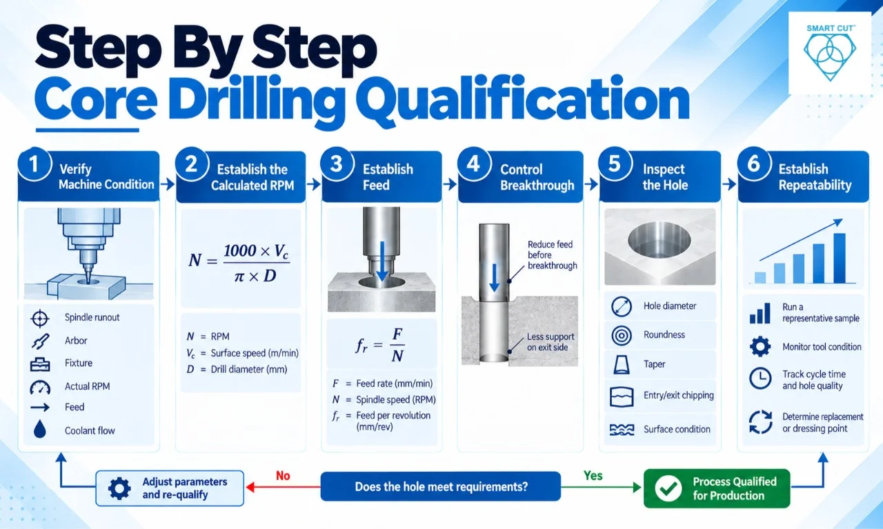
Phase 1: Verify Machine Condition
Before testing the tool, define what constitutes success.
|
Machine check |
What to verify |
|---|---|
|
Spindle runout |
Actual measured radial runout |
|
Arbor |
Clean seating surface and no damage |
|
Fixture |
No workpiece movement |
|
Spindle |
Actual RPM matches programmed value |
|
Feed |
Consistent movement |
|
Coolant |
Adequate flow into cutting zone |
A tool should not be declared successful because the first few components pass inspection.
Phase 2: Verify Machine Condition
Check the equipment before changing tooling.
- Spindle runout
- Arbor or holder condition
- Workholding
- Machine stiffness
- Tool mounting
- Coolant delivery
- Spindle speed capability
- Feed capability
- Machine vibration
This prevents a machine problem from being incorrectly attributed to the diamond tool.
Phase 3: Establish the Initial Process Window
Document:
- Tool specification
- Tool diameter
- RPM
- Peripheral speed
- Feed rate
- Feed per revolution where applicable
- Depth of cut
- Coolant condition
- Workpiece support
- Dressing or conditioning procedure where applicable
Do not change multiple major variables simultaneously unless the objective is a controlled experiment designed to evaluate their combined effect.
Phase 4: Run a Controlled Trial
Measure both the tool and the workpiece.
Record:
- spindle load
- cycle time
- tool wear
- surface finish
- edge condition
- dimensional variation
- coolant condition
- dressing response
- scrap rate
A controlled trial allows the engineer to determine whether a process change actually improved the result.
Phase 5: Diagnose the Failure Mode
Failure Mode Decision Matrix
The matrix does not prescribe one universal correction. It establishes an investigation sequence.
Phase 6: Measure the Tool and Workpiece
Tool and Workpiece Diagnostic Table
The tool itself is a source of process information.
Photographs, microscopic inspection, spindle-load trends, surface-finish measurements, and dimensional records can reveal more than a simple statement that a tool “wore out.”
Phase 7: Validate Production Economics
Tool qualification is incomplete until performance is connected to production economics.
Track:
- tool purchase cost
- usable tool life
- dressing frequency
- cycle time
- machine time
- labor
- setup
- inspection
- coolant
- scrap
- tool-change time
The final comparison should be based on the cost of producing an acceptable component.
8. Material-Specific Qualification
Different materials create different process risks. The correct qualification criteria should reflect the material’s behavior rather than treating all hard or brittle materials as one category.
Primary failure mode to investigate: edge chipping and subsurface damage.
Evaluate:
- entry and exit edges
- workpiece support
- feed behavior
- tool wear
- surface integrity
Dimensional accuracy alone does not establish acceptable surface integrity.
|
Parameter |
Qualification focus |
|---|---|
|
Surface speed |
Stable cutting response |
|
Feed |
Controlled mechanical loading |
|
Grit |
Balance productivity and edge quality |
|
Coolant |
Stable cutting zone |
|
Inspection |
Entry and exit damage |
Silicon Carbide
Primary failure mode to investigate: microchipping and unstable abrasive wear.
Evaluate:
- tool wear
- spindle load
- edge condition
- surface damage
- abrasive exposure
A change in cutting load should be correlated with tool condition before the tool specification is changed.
Sapphire
Primary failure mode to investigate: entry and exit chipping.
Evaluate:
- breakthrough behavior
- workpiece support
- feed
- tool condition
- hole or cut geometry
Entry and exit surfaces should be inspected separately because the mechanical conditions can differ (see diamond core drills and tools for gemstone and lapidary materials).
Fused Silica and Quartz
Primary failure mode to investigate: cracking and edge breakout.
Evaluate:
- entry and exit damage
- feed
- tool condition
- workpiece support
- microscopic surface condition
For optical or semiconductor applications, the inspection method should be defined before the qualification trial.
Semiconductor Materials
UKAM’s application guide identifies semiconductor materials including silicon, germanium, gallium arsenide, gallium nitride, indium phosphide, silicon carbide, and other compound semiconductor materials.
Primary qualification concerns: edge integrity, surface condition, dimensional accuracy, contamination control, and process repeatability.
The appropriate evaluation depends on the actual semiconductor material and operation. A wafer slicing process, for example, presents different requirements from drilling or sample preparation.
Composite Materials
UKAM’s application guide includes polymer matrix, metal matrix, and ceramic matrix composites, along with carbon fiber, glass fiber, honeycomb, resin, and other composite structures.
Primary failure modes to investigate: delamination, fiber pullout, and matrix damage.
Evaluate:
- fiber orientation
- laminate structure
- tool wear
- matrix damage
- delamination
- edge quality
- debris evacuation
The composite architecture should be documented rather than treating all composites as one material class.
Glass
UKAM identifies multiple glass and quartz categories, including soda-lime glass, borosilicate glass, quartz glass, technical glass, fused silica/fused quartz, electronic glass, and optical materials.
Primary failure modes to investigate: edge breakout and cracking.
Evaluate:
- entry condition
- exit condition
- workpiece support
- feed
- tool exposure
- surface damage
The required edge condition should be defined before testing.
9. Production Trial Acceptance Matrix
A controlled trial becomes a qualification when the acceptance criteria are defined before testing.
The engineering conclusion should be measurable.
Instead of:
“The new tool seems better.”
The qualification report should establish something closer to:
“The tested tooling configuration maintained the required dimensional and surface criteria throughout the defined production interval while meeting the established cycle-time and scrap requirements.”
10. Cost Per Acceptable Part
Tool purchase price alone does not determine production cost.
Illustrative Supplier Comparison
The following values are hypothetical and demonstrate the calculation method only. They are not UKAM pricing or actual supplier performance data.
Supplier A:
$180÷180=$1.00
$1.00÷0.96=$1.04
Supplier B:
$240÷320=$0.75
$0.75÷0.985=$0.76
These calculations isolate tooling cost for illustration.
A complete manufacturing cost model should also include machine time, labor, dressing, setup, inspection, coolant, and scrap cost.
The engineering principle is:
Compare the cost of producing an acceptable component, not simply the purchase price of the tool.
Supplier comparisons should use equivalent conditions wherever practical. A tool life value from one material grade or machine should not automatically be transferred to another application.
11. UKAM Technology Example: 115DE SMART CUT Series
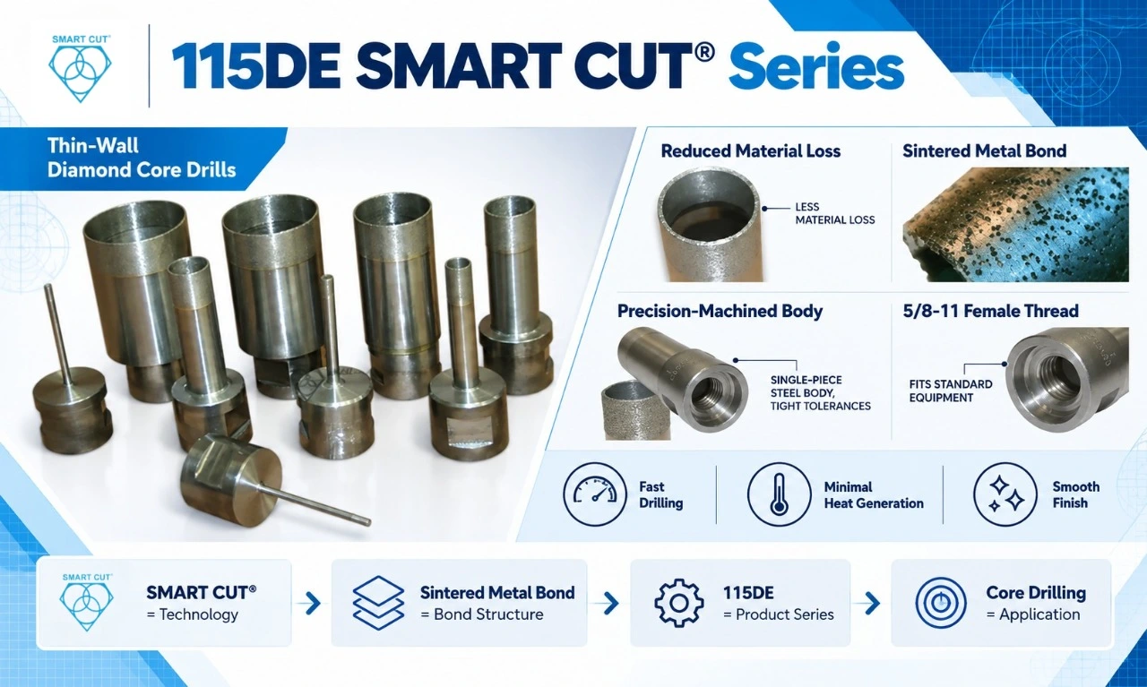
UKAM’s 115DE SMART CUT Series provides a useful example of why tool selection should be considered at the product-configuration level.
UKAM publishes the 115DE as a thin-wall diamond core drill with a sintered metal bond. The published application list includes glass, alumina, quartz, ruby, YAG, silica, silicon, graphite, composites, and other nonmetallic ceramics.
UKAM also publishes product-specific specifications for this series, including available diameters, bond type, mounting configuration, drill depth, diamond size, and dimensional tolerances. Those values belong to the specific product and should not be generalized to every SMART CUT tool.
This distinction is important:
SMART CUT = technology
Sintered metal bond = bond structure
115DE = specific product series
Core drilling = application
Those are related but different levels of the engineering decision.
12. SMART CUT Technology: How Engineers Should Evaluate It
UKAM describes SMART CUT as a technology in which diamond or CBN crystals are oriented within the matrix. Its published description also discusses an open-bond structure and controlled abrasive exposure as the bond wears.
For engineering qualification, the relevant questions are:
|
Qualification item |
Status |
|---|---|
|
Spindle runout measured |
☐ |
|
Arbor inspected |
☐ |
|
Fixture rigidity verified |
☐ |
|
Actual RPM verified |
☐ |
|
Feed system verified |
☐ |
|
Coolant flow verified |
☐ |
UKAM publishes performance claims for SMART CUT technology, including claims regarding tool life, cutting speed, and productivity. Those claims are manufacturer-specific and should not be presented as universal performance values.
For a production qualification, measured results from the actual application should take precedence over generalized performance claims.
13. Supplier Evaluation for Engineers
A technically capable tooling supplier should be able to discuss more than product availability.
Questions to Ask
A strong supplier recommendation should produce a testable engineering plan, not simply a catalog part number.
UKAM’s application-engineering service states that its applications engineers review material, machine, and cutting parameters when recommending a diamond or CBN tooling solution.
14. Engineering Decision Tree
Use this sequence before releasing a new diamond tool into production:
1. What is the material?
↓
2. What is the exact operation?
↓
3. What quality characteristic is limiting?
↓
4. What failure mode is occurring?
↓
5. Is the machine and workholding stable?
↓
6. Which grit, bond, concentration, and geometry should be evaluated?
↓
7. What process window will be tested?
↓
8. What measurements define success?
↓
9. What tool wear pattern occurs during the trial?
↓
10. Does the tool meet quality and tool-life requirements?
↓
11. What is the cost per acceptable part?
↓
12. Has the result been reproduced under production conditions?
This prevents the common mistake of treating tool selection as the end of the engineering process.
Production Qualification Checklist
Material
- Exact material and grade documented
- Material condition documented
- Relevant material properties available
- Fracture sensitivity identified
- Thermal sensitivity identified
- Composite architecture documented where applicable
Application
- Cutting, drilling, grinding, lapping, polishing, dicing, or other operation defined
- Workpiece geometry documented
- Feature dimensions documented
- Tolerance defined
- Surface finish defined
- Edge condition defined
- Failure mode identified
Machine
- Spindle runout measured
- Arbor or holder inspected
- Workholding verified
- Machine stiffness reviewed
- Coolant delivery verified
- RPM capability confirmed
- Feed capability confirmed
Tool
- Diameter recorded
- Grit recorded
- Bond recorded
- Concentration recorded where available
- Geometry documented
- Tool condition recorded before trial
- Tool condition recorded after trial
Process
- RPM recorded
- Peripheral speed calculated
- Feed recorded
- Feed per revolution calculated where applicable
- Depth of cut recorded
- Coolant conditions recorded
- Dressing procedure documented where applicable
Qualification
- Baseline established
- Acceptance criteria defined
- Controlled trial completed
- Tool wear documented
- Workpiece quality measured
- Failure mechanism evaluated
- Corrective action verified
- Production run completed
- Cost per acceptable part calculated
Frequently Asked Questions
There is no single factor that determines the correct diamond tool. Material, application, geometry, quality requirements, machine capability, abrasive specification, bond, operating conditions, and production objectives interact. The appropriate configuration is the one that consistently produces the required result under the actual process conditions.
Not necessarily. Grit and bond should be evaluated together because bond behavior influences how abrasive particles are retained and exposed. A grit that appears appropriate in isolation can behave differently when paired with another bond, concentration, geometry, or operating condition.
Measure tool condition against production results. Track dimensional accuracy, surface finish, spindle load, cycle time, tool wear, and edge condition. Uneven wear, rapid abrasive loss, increasing load, or declining cutting rate can indicate a change in the tooling or process condition that requires investigation.
Runout changes the actual contact between the abrasive tool and workpiece. Excessive runout can produce uneven loading, localized wear, vibration, dimensional variation, and edge damage. Measuring it before the trial helps separate machine-related effects from tooling-related effects.
UKAM describes SMART CUT as a technology in which diamond or CBN crystals are oriented within the matrix to participate in the machining action. UKAM also describes an open-bond design intended to maintain abrasive exposure as the bond wears.
SMART CUT should therefore be understood as a technology approach, not as a generic name for every diamond blade, drill, wheel, or polishing tool.
No universal rule should be applied. Concentration changes abrasive density and interacts with bond behavior, cutting conditions, material response, and finish requirements. The appropriate concentration should be established from the actual application and qualification criteria.
Tool life should be tied to an objective production criterion. Depending on the operation, that may be acceptable holes, cuts, components, grinding cycles, or finishing operations before the process exceeds its dimensional, surface, edge-quality, removal-rate, or other defined limit.
A lower-priced tool can create higher manufacturing cost if it has shorter life, longer cycle time, greater dressing requirements, or higher scrap. Cost per acceptable part connects tooling cost with production yield and provides a more meaningful engineering and purchasing comparison.
Provide the exact material and grade, workpiece geometry, required tolerance, surface finish, machine and spindle information, tool diameter, current tool specification, RPM, feed, coolant conditions, tool life, cycle time, scrap rate, and observed failure mode. Tool-wear photographs and workpiece inspection results can also improve technical evaluation.
A trial is successful when the tooling configuration repeatedly meets predefined acceptance criteria under representative production conditions. The criteria should cover the relevant combination of dimensional accuracy, surface finish, edge integrity, tool life, cycle time, scrap rate, and process stability.
17. Key Engineering Principles
- Start with the exact material and application rather than material name alone.
- Define the failure mode before changing tooling.
- Treat grit, bond, concentration, geometry, machine condition, and process parameters as an interconnected system.
- Establish a documented baseline before the tooling trial.
- Compare peripheral speed rather than RPM alone for rotating tools.
- Use feed per revolution when comparing rotating processes at different spindle speeds.
- Verify spindle runout, workholding, and coolant delivery before modifying tooling unnecessarily.
- Use tool wear and workpiece damage as process evidence.
- Match the corrective action to the identified failure mechanism.
- Evaluate entry and exit damage separately where brittle fracture is a concern.
- Define tool life using measurable quality or production criteria.
- Compare suppliers using cost per acceptable part rather than purchase price alone.
- Keep manufacturer-specific performance claims separate from general engineering principles.
- Keep illustrative calculations separate from actual manufacturer specifications.
- Validate the final configuration under representative production conditions.
Engineering Application Support
A reliable diamond tooling decision starts with application data.
For an application-specific evaluation, provide:
- Material and exact grade
- Workpiece geometry and thickness
- Required dimensional tolerance
- Surface finish requirement
- Edge or chipping limit
- Machine and spindle capability
- Tool diameter and configuration
- Current tool specification
- RPM and feed
- Coolant type and delivery conditions
- Current tool life
- Cycle time
- Scrap rate
- Photographs or measurements of the failure mode
UKAM states that its application engineers review the material, machine, and cutting parameters when helping customers select a diamond or CBN tooling solution.
The engineering objective is therefore not simply to identify a diamond tool that can cut a material.
It is to select a tooling configuration, establish a controlled process window, measure the failure mechanism, validate quality and tool life, and prove the economics before making the configuration a production standard.
That is the difference between tool selection and tool qualification.
Trusted by Tens of Thousands of Manufacturers, Laboratories,
Research Institutions Worldwide Since 1990
American Based Manufacturer
Established in 1990
