























Custom Diamond Tool RFQ: What Engineering Data Should You Give Your Tool Manufacturer?

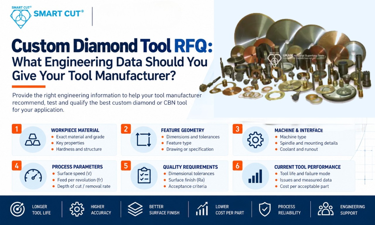
Table of Contents
Toggle
American Based Manufacturer

Established in 1990


Custom manufacturing


A custom diamond tool should not be specified from diameter, thickness, and grit size alone.
An incomplete specification can produce a tool that fits the machine correctly but fails to control edge damage, dimensional stability, surface finish, tool wear, cycle time, or cost per acceptable part.
For a manufacturer to develop a useful custom tool specification, the application must be described as a complete manufacturing process. That includes the exact workpiece material, operation, feature geometry, machine interface, spindle condition, operating parameters, coolant, quality requirements, current tool performance, and the failure that needs to be corrected.
For engineers preparing a custom diamond tool RFQ, the objective is not simply to describe a tool. The objective is to provide enough engineering data for the manufacturer to recommend a specification that can be tested, measured, and qualified.
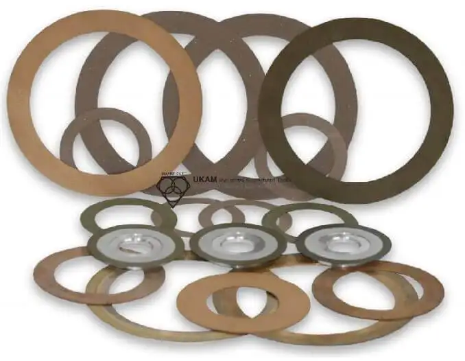
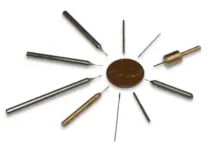
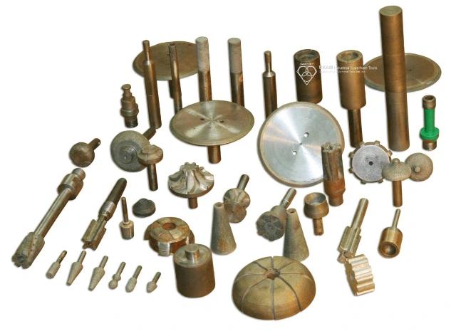
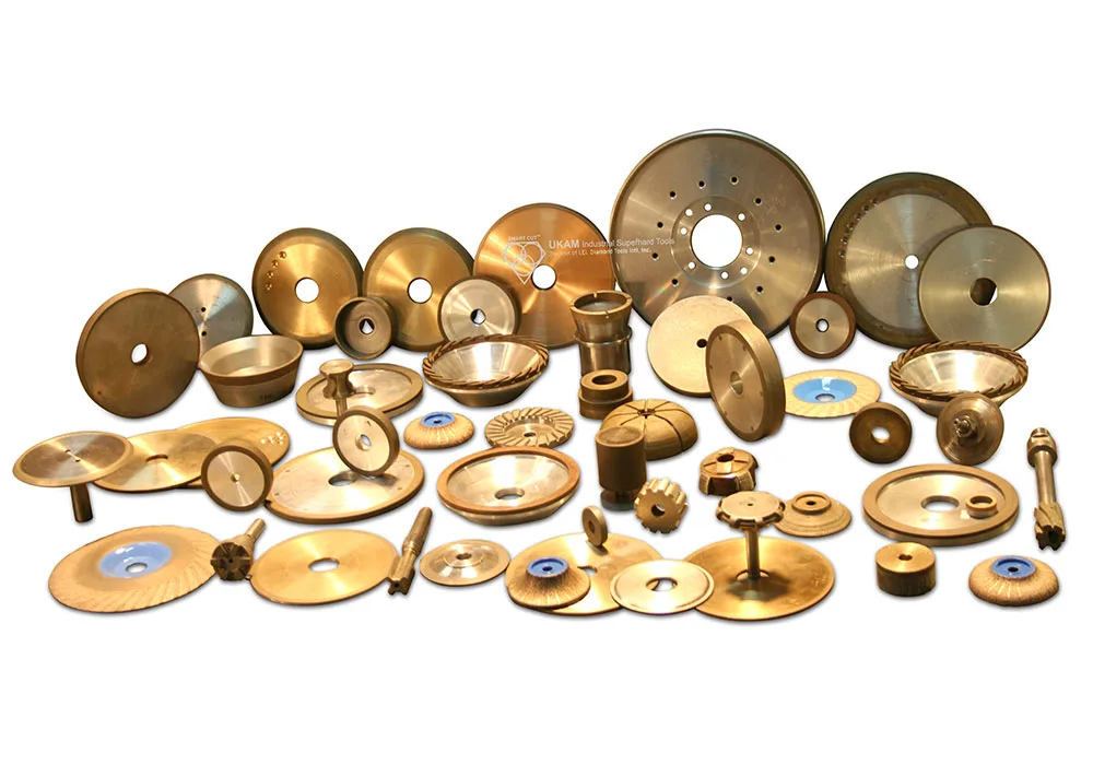
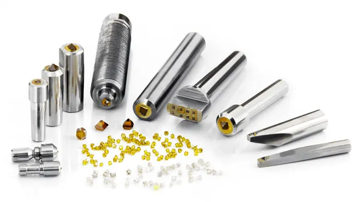
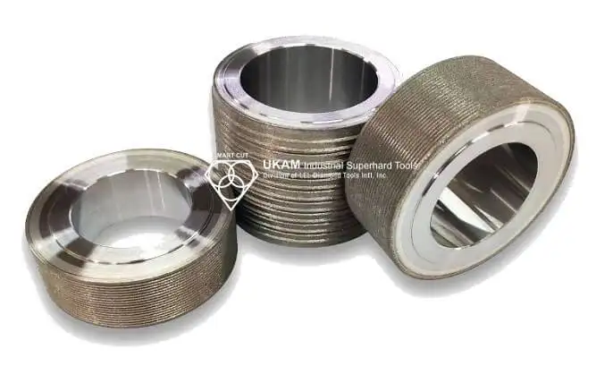
UKAM manufactures custom diamond and CBN tools around application requirements including material, equipment, tolerances, surface finish, tool life, bond, concentration, grit, geometry, and mounting requirements. Its published custom manufacturing process includes application discovery, solution recommendation, written specification, production and inspection, and technical support.
Start With the Production Problem
A custom tooling RFQ should begin with a measurable manufacturing problem rather than a preferred tool specification.
A standard diamond tool may perform adequately for general cutting, drilling, grinding, dicing, or polishing but fail when the application requires a particular tolerance, surface finish, feature geometry, production rate, edge condition, or tool life.
Before asking a manufacturer to change the tool, define exactly what the current process is failing to achieve.
|
Production problem |
Engineering data that should define it |
|---|---|
|
Excessive edge chipping |
Maximum acceptable chip size and percentage of affected parts |
|
Short tool life |
Number of acceptable parts before the defined failure point |
|
Current Ra or Rz and required target |
|
|
Dimensional drift |
Dimension change versus tool wear or part count |
|
Parts between dressing operations and dressing time |
|
|
Slow cycle time |
Current cycle time and required production rate |
|
Current kerf width and permitted material loss |
|
|
Point in the cycle where loading begins |
|
|
Profile loss |
Initial and final measured tool profile |
|
High scrap |
Scrap percentage and classified rejection causes |
|
Mounting limitation |
Required bore, arbor, shank, flange, or mandrel |
|
Difficult feature access |
Component drawing and dimensional envelope |
The statement “the tool does not last long enough” is not an engineering specification.
A more useful statement is:
The current tool produces 1,400 acceptable parts before dimensional error exceeds 0.020 mm.
That statement gives the manufacturer a measurable production target.
Engineer Insight
Before requesting a new tool, define what failure ends the tool’s useful life.
Tool life can mean loss of dimensional accuracy, unacceptable surface finish, excessive edge damage, reduced cutting rate, increased spindle load, profile loss, or physical tool failure. These are different failure endpoints and can lead to different tooling recommendations.
Define the Workpiece Precisely
Material identification is one of the first inputs required for abrasive and bond selection.
“Ceramic,” “carbide,” “glass,” or “steel” may describe a material family, but those terms do not necessarily define the machining behavior of the actual component.
An RFQ should identify the following information.
|
Workpiece information |
Example of useful data |
|---|---|
|
Material |
Silicon carbide |
|
Grade |
Manufacturer or internal grade designation |
|
Hardness |
Measured or specified value where applicable |
|
Density |
Actual or specified density |
|
Dimensions |
Thickness, OD, ID, length, width |
|
Condition |
Green, sintered, heat treated, coated, polished |
|
Microstructure |
Relevant grain, binder, or structural information |
|
Feature |
Hole, slot, OD, face, profile, edge |
|
Stock allowance |
Material to be removed |
|
Part value |
Approximate production value where relevant |
|
Production quantity |
Parts per shift, lot, month, or year |
This level of detail becomes particularly important for silicon carbide, alumina, silicon nitride, tungsten carbide, sapphire, fused silica, GaAs, PCD, and hardened steels.
A material family does not define a complete machining condition.
For example, two tungsten carbide grades can have different binder percentages and carbide grain structures. Two alumina components can have different purity levels and microstructures. Those differences can influence grinding behavior, edge damage, material removal, and acceptable tool life.
RFQ Checkpoint
Another engineer should be able to read the material section of the RFQ and identify the same workpiece without having to guess the material grade or condition
Document the Existing Process Before Changing the Tool
A tooling trial without a baseline is difficult to interpret.
If spindle speed, feed, coolant delivery, workholding, dressing, or another major process variable changes at the same time as the tool, the resulting improvement cannot be attributed confidently to the tool specification.
Record the actual production process before making the tooling change.
|
Parameter |
Baseline information |
|---|---|
|
Machine |
Manufacturer and model |
|
Spindle |
Type, RPM range, actual operating RPM |
|
Spindle runout |
Measured value |
|
Current tool |
Manufacturer, model, complete specification |
|
Tool geometry |
OD, ID, thickness, profile, working layer |
|
Abrasive |
Diamond or CBN |
|
Grit |
Mesh or micron specification |
|
Concentration |
Current value if known |
|
Bond |
Current bond type and grade if known |
|
Feed |
Actual production feed |
|
Infeed |
Depth of cut or stock removal |
|
Surface speed |
Calculated operating value |
|
Coolant |
Type and concentration |
|
Coolant delivery |
Flow, filtration, nozzle position |
|
Method, interval, and duration |
|
|
Cycle time |
Actual machining time |
|
Tool life |
Acceptable parts per tool |
|
Scrap |
Percentage and rejection category |
|
Quality |
Dimensions, Ra or Rz, edge condition |
The baseline should describe the actual production process, not the machine’s maximum capability.
A machine capable of a particular RPM does not mean that RPM is being used during production. The RFQ should contain the actual operating condition used during the trial.
Use Basic Process Calculations to Describe the Application
Simple calculations can prevent incomplete or misleading tooling specifications.
They do not replace application testing, but they provide a common engineering language for comparing processes.
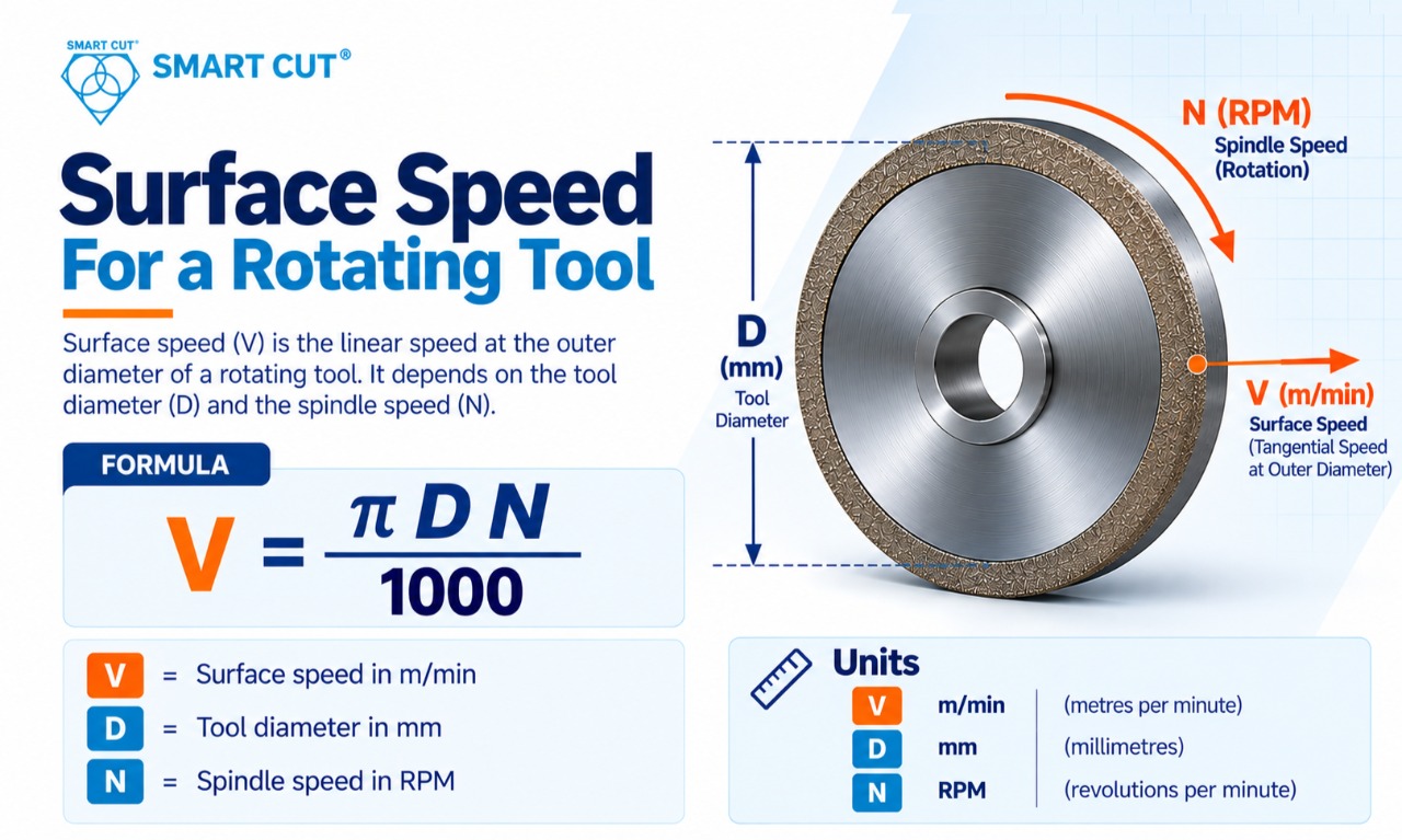
Surface Speed
For a rotating tool:
V = πDN / 1000
Where:
V = surface speed in m/min
D = tool diameter in mm
N = spindle speed in RPM
Rearranged for RPM:
N = 1000V / πD
For example, a 25 mm tool operating at a calculated surface speed of 20 m/min would run at approximately:
N = 1000 × 20 / (π × 25) ≈ 255 RPM
The actual operating range must remain within the tool and machine manufacturer’s specifications.
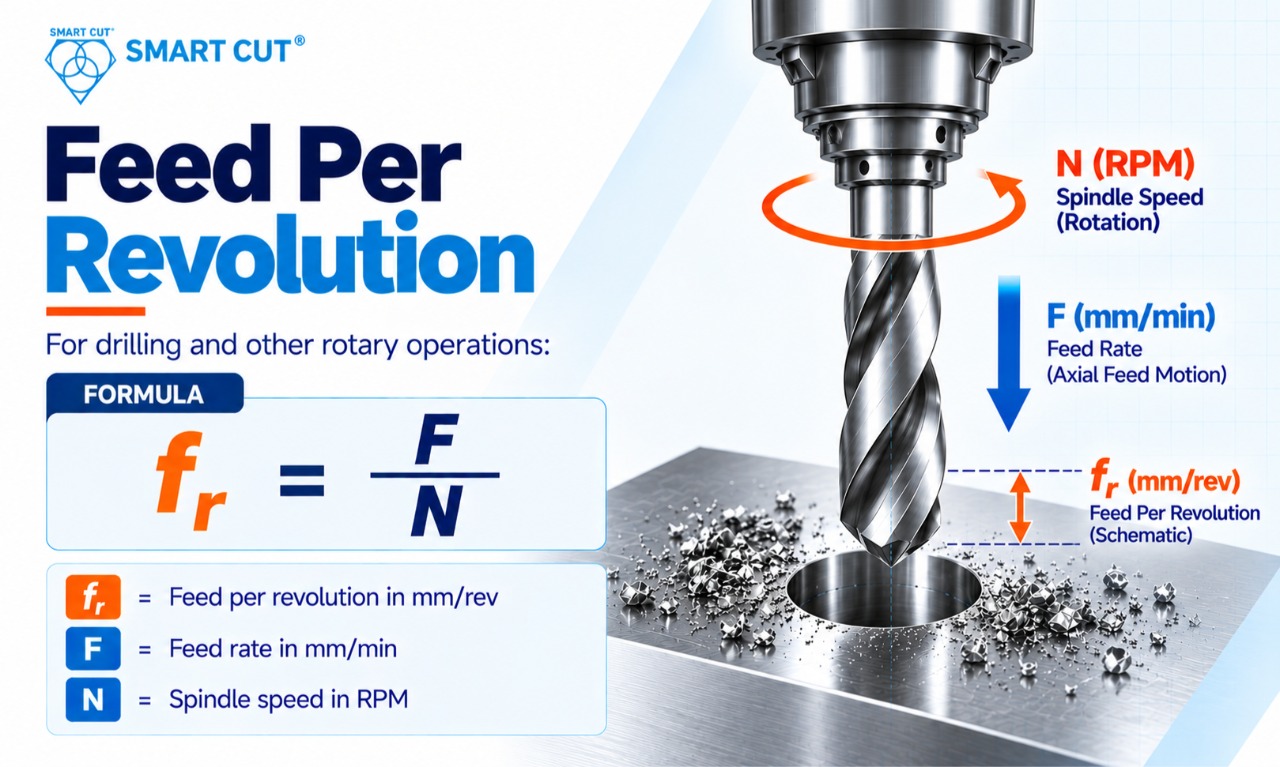
Feed Per Revolution
For drilling and other rotary operations:
fᵣ = F / N
Where:
fᵣ = feed per revolution in mm/rev
F = feed rate in mm/min
N = spindle speed in RPM
For example, if the feed is 60 mm/min at 600 RPM:
fᵣ = 60 / 600 = 0.10 mm/rev
Feed per revolution can be more informative than feed rate alone when comparing trials performed at different spindle speeds.
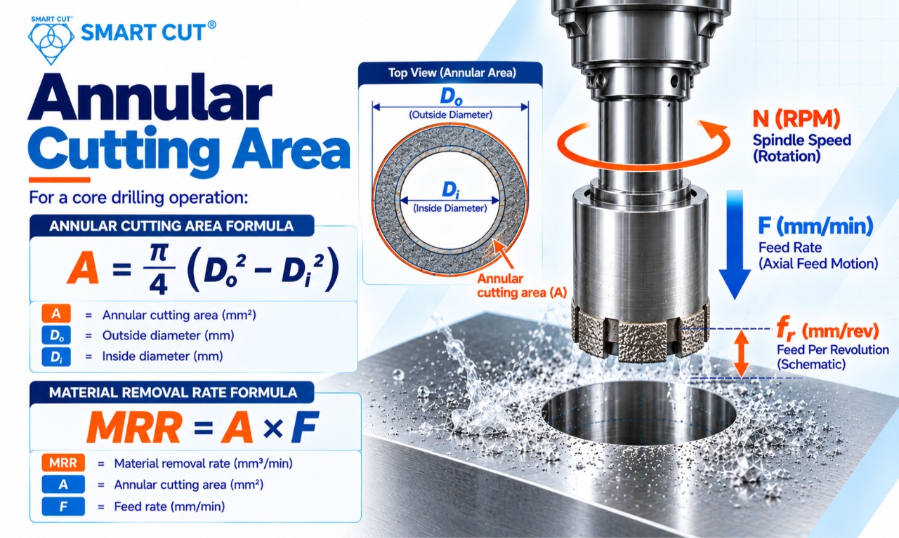
Annular Cutting Area
For a core drilling operation:
A = π/4 × (Dₒ² − Dᵢ²)
Where:
A = annular cutting area
Dₒ = outside diameter
Dᵢ = inside diameter
If feed is expressed as axial feed rate:
MRR = A × F
Where:
MRR = material removal rate
A = annular cutting area
F = feed rate
These calculations provide useful process context for the manufacturer.
They do not determine the final grit, bond, concentration, or tool geometry by themselves.
Define Cost Per Acceptable Part Correctly
Tool purchase price is only one component of tooling economics.
A lower priced tool can produce a higher manufacturing cost if it has shorter usable life, longer cycle time, more frequent dressing, greater scrap, or more rework.
A useful production metric is:
Cost per acceptable part = Total process cost / Acceptable parts produced
Total process cost can include:
- Tool cost
- Machine time
- Dressing
- Labor
- Scrap
- Rework
- Tool changes
- Inspection
- Coolant or consumables where significant
For supplier comparisons, it is useful to separate tool purchase cost per produced part from tool purchase cost per acceptable part.
The following example is illustrative only. It does not represent UKAM pricing or guaranteed performance.
|
Metric |
Supplier A |
Supplier B |
|---|---|---|
|
Tool price |
$480 |
$720 |
|
Parts produced per tool |
1,600 |
3,000 |
|
Dressing interval |
200 parts |
600 parts |
|
Dressing time |
6 min |
4 min |
|
Cycle time |
4.8 min |
4.1 min |
|
Scrap rate |
4.0% |
1.5% |
|
Tool purchase cost per produced part |
$0.30 |
$0.24 |
|
Acceptable parts per tool |
1,536 |
2,955 |
|
Tool purchase cost per acceptable part |
$0.3125 |
$0.2437 |
The calculation is:
Supplier A
1,600 produced parts × 96% acceptable = 1,536 acceptable parts
$480 ÷ 1,536 = $0.3125 per acceptable part
Supplier B
3,000 produced parts × 98.5% acceptable = 2,955 acceptable parts
$720 ÷ 2,955 = approximately $0.2437 per acceptable part
Supplier B has the higher initial tool price but the lower tool purchase cost per acceptable part.
The full economic comparison becomes more meaningful when the plant also includes machine time, labor, dressing downtime, scrap, rework, material loss, tool changes, inspection, and other measurable production costs.
Engineer Insight
When a tooling trial is reviewed by procurement, present both the tool purchase price and the cost per acceptable part.
This prevents a higher priced tool from appearing uneconomical simply because its purchase price is higher.
Provide Measured Evidence of Tool Failure
A photograph of a worn tool can be useful, but measured production data is more useful.
The manufacturer needs to know where the tool fails and when the failure begins.
|
General description |
Engineering description |
|---|---|
|
Profile changes 0.08 mm after 350 parts |
|
|
Poor surface finish |
Ra increases from 0.42 µm to 0.91 µm after 180 parts |
|
Too much chipping |
Chips above 75 µm occur on 3.8% of parts |
|
Frequent dressing |
Dressing required every 120 parts |
|
Tool gets hot |
Thermal discoloration appears after repeated 90 second cuts |
|
Hole size changes |
Diameter shifts 0.025 mm during one production lot |
|
Tool loses shape |
Profile error reaches 0.05 mm after 700 parts |
Different failures can require different engineering responses.
Premature wear may require investigation of bond behavior, concentration, abrasive size, operating conditions, or dressing.
Chipping may require investigation of grit, tool geometry, feed, support, runout, workholding, or machine stability.
Thermal damage may point toward speed, feed, coolant delivery, contact conditions, abrasive behavior, or insufficient heat removal.
The purpose of the RFQ is not to tell the manufacturer what variable to change. The purpose is to provide enough evidence for the manufacturer to determine which variables require investigation.
Decide Whether Diamond or CBN Fits the Application
Diamond and CBN should not be treated as interchangeable superabrasives.
Diamond is commonly used for hard and abrasive nonferrous materials, ceramics, glass, carbide, composites, and semiconductor materials.
CBN is commonly used for grinding hardened ferrous materials and selected difficult ferrous alloys.
The exact workpiece, material grade, operation, and process determine the appropriate abrasive.
|
Material |
Abrasive to evaluate |
Primary qualification concern |
|---|---|---|
|
Silicon carbide |
Diamond |
Brittle fracture and subsurface cracking |
|
Alumina |
Diamond |
Edge breakout and grain pullout |
|
Silicon nitride |
Diamond |
Surface integrity and microcracking |
|
Tungsten carbide |
Diamond |
Edge microchipping and thermal effects |
|
Sapphire |
Diamond |
Edge chipping and subsurface damage |
|
Fused silica |
Diamond |
Edge fracture and cracking |
|
GaAs |
Diamond |
Wafer edge fracture and chipping |
|
PCD |
Diamond |
Profile retention and grinding efficiency |
|
Hardened tool steel |
CBN |
Grinding burn and dimensional stability |
|
Hardened alloy steel |
CBN |
Thermal damage and wheel wear |
The material grade should still be provided.
“Hardened steel” or “ceramic” does not contain enough information for a complete tooling specification.
Select the Bond as Part of the Process
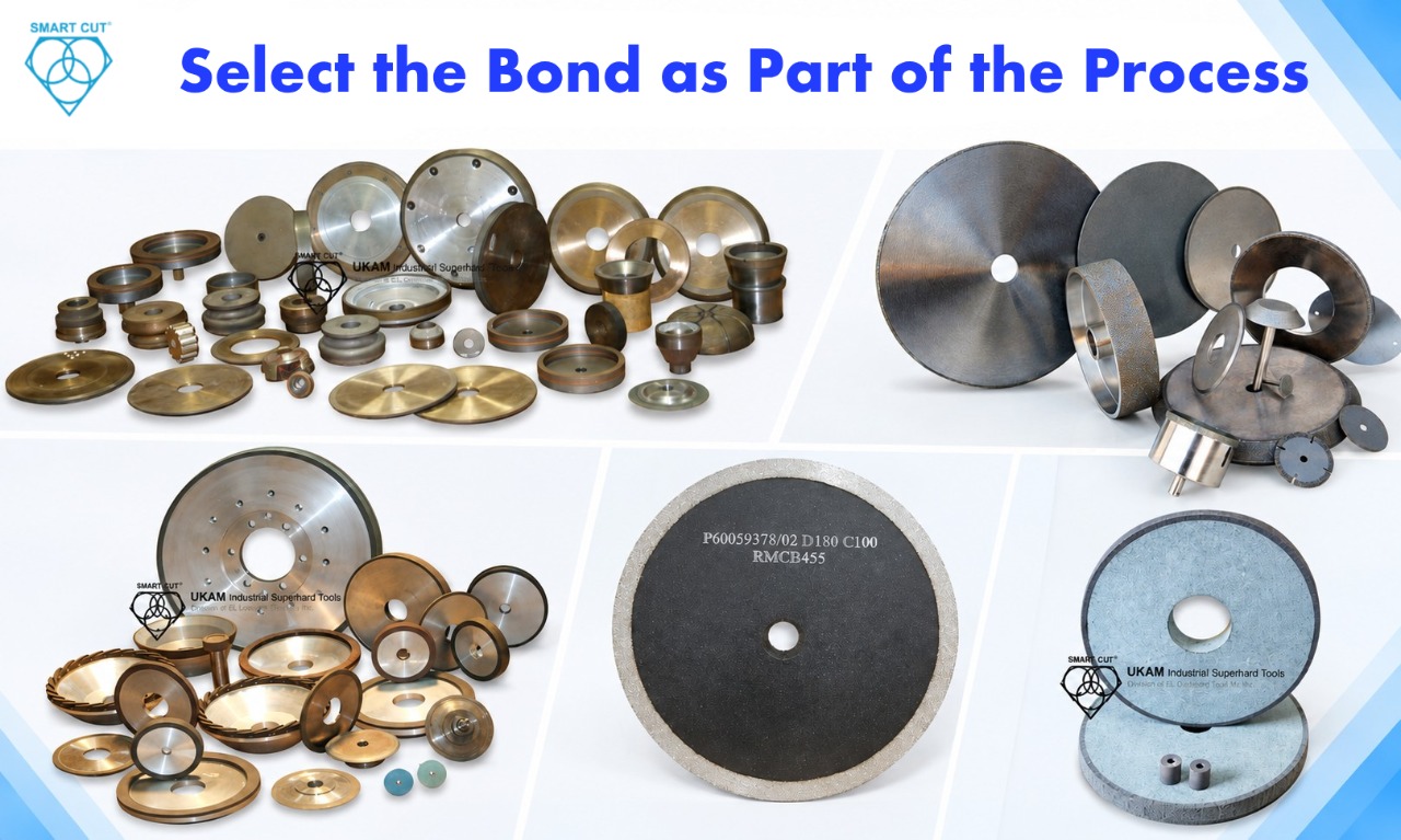
Bond selection should be treated as part of the complete tooling system.
Bond behavior interacts with material, abrasive size, concentration, geometry, machine capability, coolant, material removal rate, surface requirements, dressing, and tool life.
UKAM currently lists multiple diamond and CBN tooling technologies, including sintered metal bond, resin bond, hybrid bond, nickel electroplated bond, brazed bond, vitrified bond, PCD, and CVD technologies.
|
Technology |
Engineering variable to evaluate |
Qualification focus |
|---|---|---|
|
Sintered metal bond |
Abrasive retention and working layer |
Tool life, removal rate, form retention |
|
Resin bond |
Bond compliance and cutting behavior |
Surface finish, grinding forces, wear |
|
Hybrid bond |
Combined bond characteristics |
Finish, cutting action, life |
|
Nickel electroplated |
Abrasive exposure and fixed geometry |
Cutting efficiency, profile retention |
|
Brazed bond |
Grain exposure and attachment |
Stock removal, thermal behavior |
|
Vitrified bond |
Porosity and dressing response |
Finish, forces, dressability |
|
PCD |
Polycrystalline cutting structure |
Edge condition and wear |
|
CVD diamond |
Deposited diamond structure |
Wear resistance and geometry retention |
No bond should be selected simply because it worked in another application.
The relevant question is whether the bond supports the required abrasive behavior, material removal, surface condition, geometry retention, and production life under the actual process conditions.
Specify Grit and Concentration From the Required Result
Grit size is connected to cutting behavior and surface condition.
A finer abrasive can support a finer finish, while a coarser abrasive can provide a different balance between cutting action, stock removal, and surface condition.
Concentration affects the amount and distribution of active abrasive in the working layer.
The manufacturer should receive both the current specification and the desired production result.
|
Specification |
Information to provide |
|---|---|
|
Abrasive |
Diamond or CBN |
|
Grit |
Current grit and required finish |
|
Concentration |
Current value if known |
|
Bond |
Current bond if known |
|
Bond hardness |
Current value if known |
|
Working layer |
Thickness and functional requirement |
|
Geometry |
Complete tool drawing |
|
Mounting |
Bore, arbor, shank, flange, or mandrel |
|
Speed |
RPM and surface speed |
|
Removal |
Stock per pass or total stock |
|
Finish |
Required Ra or Rz |
|
Tool life |
Minimum acceptable parts |
The important point is that grit should not be specified independently from the required result.
A request such as:
“We need 220 grit diamond.”
is incomplete unless the RFQ also explains the material, stock removal, surface requirement, current process, machine, and expected tool performance.
Machine Condition Belongs in the RFQ
A diamond or CBN tool does not operate independently of the machine.
Spindle runout, machine stiffness, horsepower, workholding, arbor condition, coolant delivery, available RPM, and vibration can all affect the result.
This becomes particularly important for thin blades, micro tools, precision grinding wheels, small diameter drills, and applications with tight dimensional requirements.
Machine Checklist
A precision tool cannot correct excessive spindle runout or unstable workholding.
Engineer Insight
If a new tool produces inconsistent results from one machine to another, do not immediately assume the tool specification is wrong.
Compare:
- Spindle runout
- Workholding
- Coolant delivery
- Speed
- Feed
- Machine stiffness
- Arbor or flange condition
Tool performance is a process result, not an isolated product attribute.
Build the Custom Diamond Tool RFQ in Six Phases
A useful RFQ can be organized into six engineering phases.
Phase 1: Define the Material
Record the exact material, grade, condition, dimensions, and hardness where applicable.
Checkpoint: Another engineer should be able to identify the same workpiece from the RFQ.
Phase 2: Define the Feature
Identify exactly what the tool must produce.
Include:
- Feature dimensions
- Tolerances
- Profile
- Surface finish
- Edge requirements
- Access restrictions
- Drawing references
Checkpoint: The drawing identifies the functional requirements that the tool must achieve.
Phase 3: Define the Machine Interface
Provide:
- Shank
- Mounting arrangement
- Clearance
- Available power
- Machine model
- Spindle type
- Operating RPM
- Arbor
- Flange
Checkpoint: The proposed tool can physically mount and operate within the machine’s actual capability.
Phase 4: Define the Process
Record:
- Speed
- Feed
- Depth of cut
- Stock removal
- Coolant
- Dressing
- Workholding
- Production sequence
- Cycle time
Checkpoint: The trial process can be repeated under controlled conditions.
Phase 5: Define the Failure
Document:
- Tool wear
- Quality failure
- Cycle time
- Tool life
- Scrap
- Dressing requirement
- Dimensional drift
- Edge damage
Checkpoint: The failure can be measured.
Phase 6: Define Acceptance
Set the targets before the supplier trial.
|
Qualification criterion |
Baseline |
Target |
|---|---|---|
|
Tool life |
Record |
Minimum acceptable parts |
|
Cycle time |
Record |
Maximum acceptable time |
|
Surface finish |
Record |
Required Ra or Rz |
|
Dimensional accuracy |
Record |
Required tolerance |
|
Edge damage |
Record |
Maximum permitted |
|
Scrap |
Record |
Maximum percentage |
|
Dressing interval |
Record |
Minimum interval |
|
Cost per acceptable part |
Calculate |
Economic target |
This gives both the manufacturer and the customer a common definition of success.
Common Mistakes Engineers Make When Requesting Custom Tools
A technically detailed RFQ can still fail if critical variables are missing.
Mistake 1: Specifying Only Tool Dimensions
A request for a 150 mm wheel with a 25 mm bore does not describe the application.
Better approach: Provide material, operation, machine, speed, feed, finish, tolerance, current tool, and measurable failure mode.
Mistake 2: Specifying Grit Without the Desired Result
A request for “220 grit diamond” does not explain why that grit is required.
Better approach: Provide current grit, required surface finish, stock removal, and current tool performance.
Mistake 3: Reporting Tool Life Without Defining Failure
“Tool life is 500 parts” is incomplete.
Better approach: State what happens at part 500. Does the tool lose size, lose profile, produce excessive chipping, increase surface roughness, or become uneconomical?
Mistake 4: Comparing Tools at Different Process Conditions
A tool running at a different speed, feed, coolant flow, or dressing interval cannot be compared fairly with the baseline.
Better approach: Hold major process variables constant during the initial comparison.
Mistake 5: Ignoring Spindle Runout
A new tool can be blamed for inconsistent cutting when the machine interface is actually the source of variation.
Better approach: Measure runout and document mounting condition before qualification.
Mistake 6: Choosing the Lowest Tool Price
The cheapest tool may produce higher total production cost.
Better approach: Compare tool life, cycle time, dressing, scrap, rework, and cost per acceptable part.
Mistake 7: Changing Several Variables at Once
Changing grit, bond, speed, feed, coolant, and dressing simultaneously makes the result difficult to interpret.
Better approach: Establish a controlled baseline and identify which variables are being changed.
Material Specific Failure Modes
Material-specific failure modes should be included in the qualification plan because acceptable surface roughness alone does not always describe material integrity.
Silicon Carbide: Subsurface Cracking
Silicon carbide is extremely hard and brittle. A primary qualification concern is brittle fracture with subsurface cracking.
A surface can appear acceptable while damage remains below the finished surface. For critical SiC components, inspection should therefore address more than surface roughness.
Alumina: Edge Breakout and Grain Pullout
A primary failure mode in alumina grinding is edge breakout and grain pullout.
Record the alumina grade and, where relevant, microstructural information. Qualification should evaluate dimensional accuracy, surface finish, and edge condition rather than relying on one measurement.
Tungsten Carbide: Edge Microchipping
A primary failure mode in tungsten carbide is edge microchipping, with thermal effects and tool wear also requiring evaluation.
The carbide grade should be included in the RFQ because carbide composition and microstructure can affect grinding behavior.
Sapphire: Edge Chipping
Sapphire qualification should focus on edge chipping and subsurface damage.
Thin sections and high value optical or semiconductor components can make small edge defects significant. Tool runout, abrasive size, feed, support, and cutting conditions should therefore be controlled.
Fused Silica: Edge Fracture
A primary failure mode for fused silica is edge fracture and cracking.
Aggressive conditions can produce brittle damage that affects downstream yield. Qualification should include edge inspection in addition to dimensional and surface measurements.
GaAs: Wafer Edge Fracture
For GaAs, watch for wafer edge fracture and chipping.
The material value and sensitivity of semiconductor components make tool thickness, runout, feed, workholding, and abrasive behavior important process variables.
PCD: Profile Loss
For PCD, a primary qualification concern is profile loss accompanied by declining grinding efficiency.
Measure profile accuracy at defined intervals throughout tool life rather than evaluating only the first few components.
Hardened Steel: Grinding Burn
For hardened steel, watch for grinding burn, thermal damage, and dimensional drift.
CBN should be evaluated for applications where its properties are appropriate for hardened ferrous grinding. Coolant delivery, grinding conditions, wheel condition, and machine stability all contribute to thermal behavior.
Questions to Ask a Custom Diamond Tool Manufacturer
A supplier evaluation should test engineering capability, not only quotation price.
|
Question to ask |
What the answer reveals |
|---|---|
|
What application data do you need before specifying the tool? |
Whether the supplier evaluates the complete process |
|
Why are you recommending diamond or CBN? |
Material and process knowledge |
|
Why this bond? |
Understanding of abrasive retention and wear |
|
Why this grit? |
Connection between abrasive size and required result |
|
What concentration do you recommend? |
Understanding of abrasive loading and tool behavior |
|
What machine information do you require? |
Consideration of machine limitations |
|
What should remain constant during qualification? |
Trial discipline |
|
Which measurements should be collected? |
Ability to define objective success |
|
What failure mode do you expect? |
Understanding of tool behavior |
|
How will the qualified specification be documented? |
Reproducibility |
|
What changes require another qualification? |
Process control |
|
What information is required for a second iteration? |
Engineering support |
A manufacturer that only asks for diameter, bore, thickness, and grit may be treating the RFQ as a dimensional order rather than an application engineering problem.
A stronger supplier discussion connects the tool specification to the material, machine, process, quality requirements, and measurable production target.
UKAM SMART CUT and Other Tool Technologies
UKAM presents SMART CUT technology as an approach in which diamond or CBN crystal placement and orientation within the bond matrix are controlled to support consistent abrasive participation during machining.
For an engineer evaluating the technology, the useful comparison is not simply whether a technology is labeled advanced. The relevant question is how the proposed technology performs against the application’s measurable requirements.
|
Technology |
What to compare during specification |
Qualification measurements |
|---|---|---|
|
Silicon carbide |
Abrasive positioning and working layer behavior |
Cutting consistency, tool life, surface quality |
|
Sintered metal bond |
Abrasive retention and working layer |
Life, removal rate, form retention |
|
Resin bond |
Bond behavior and cutting action |
Finish, forces, wear |
|
Hybrid bond |
Combined bond characteristics |
Finish, cutting efficiency, life |
|
Nickel electroplated |
Abrasive exposure and fixed geometry |
Cutting rate, profile retention |
|
Brazed bond |
Grain exposure and attachment |
Stock removal, thermal behavior |
|
Vitrified bond |
Porosity and dressing response |
Finish, forces, dressability |
|
PCD |
Polycrystalline cutting structure |
Edge condition, wear, geometry |
|
CVD diamond |
Diamond construction |
Wear resistance, geometry retention |
SMART CUT should therefore be evaluated against the same production criteria as any other proposed tooling technology.
The correct technology is the one that satisfies the material, geometry, machine, quality, productivity, and economic requirements established during qualification.
Custom Diamond Tool Qualification Checklist
Use this checklist before sending a custom diamond tool RFQ.
- Exact material and grade
- Material condition
- Component drawing
- Critical dimensions
- Production quantity
- Component value where relevant
- Material hardness where applicable
- Relevant microstructure information
- Tool drawing
- Tool type
- Abrasive type
- Grit size
- Concentration
- Bond technology
- Working layer
- Mounting dimensions
- Tool tolerances
- Profile or edge geometry
- Machine model
- Spindle type
- Operating RPM
- Spindle runout
- Arbor or flange
- Workholding
- Coolant system
- Machine clearance
- Feed
- Speed
- Depth of cut
- Stock removal
- Coolant
- Dressing
- Cycle time
- Workpiece support
- Production sequence
- Dimensional tolerance
- Surface finish
- Edge condition
- Subsurface requirement
- Profile accuracy
- Scrap classification
- Inspection method
- Tool purchase price
- Tool life
- Dressing frequency
- Dressing time
- Cycle time
- Scrap
- Rework
- Tool changes
- Inspection
- Cost per acceptable part
Frequently Asked Questions
Provide the exact material and grade, operation, component drawing, feature dimensions, machine model, spindle speed, feed rate, coolant information, mounting dimensions, current tool specification, production quantity, quality requirements, and documented failure mode. Photographs of the worn tool and finished component can provide additional evidence. The manufacturer can use this information to evaluate the complete process rather than selecting a tool from dimensions alone.
The current grit should be included if an existing tool is being evaluated, but the final grit should be treated as part of the complete tool specification. Material, stock removal, surface finish, tool geometry, machine capability, coolant, operating conditions, and tool life can all affect the appropriate abrasive size.
A standard tool uses an established specification and geometry. A custom tool can be manufactured around application requirements such as unusual dimensions, mounting, tolerances, abrasive characteristics, bond, concentration, working layer, or geometry. Customization becomes relevant when the standard product cannot meet the required production or quality target.
Compare total production economics rather than tool price alone. Include tool life, cycle time, dressing, machine time, scrap, rework, tool changes, and other measurable process costs. A custom tool with a higher purchase price can produce a lower cost per acceptable part if it improves usable tool life or reduces production losses.
Record the baseline first and keep major process variables controlled during the comparison. Spindle speed, feed, depth of cut, coolant, workholding, dressing, and inspection methods should be documented. Define acceptance criteria before the trial so the result is based on measured production performance.
Yes. Excessive runout can create uneven abrasive engagement, vibration, dimensional variation, edge damage, and premature wear. The tool should not be used as a substitute for correcting an unstable machine interface.
Give both suppliers the same application information and evaluate their proposed specifications under comparable conditions. Compare tool price, tool life, cycle time, dressing, quality, scrap, delivery, technical support, and cost per acceptable part. The lowest quoted tool price is not necessarily the lowest production cost.
UKAM states that its custom manufacturing capability includes diamond and CBN tools manufactured according to customer drawings or specifications. Application information should still be supplied because geometry alone does not determine abrasive, grit, concentration, bond, or operating requirements.
Document the failure and identify which part of the process missed the requirement. Review abrasive type, grit, concentration, bond, geometry, speed, feed, coolant, mounting, and machine condition before changing the specification. A controlled second iteration should change identified variables rather than changing the complete process without evidence.
Engineering Principles for a Better Custom Diamond Tool RFQ
- Define the production problem before specifying the tool.
- Identify the exact workpiece material and grade.
- Provide complete component and tool drawings.
- Document spindle condition, mounting, speed, feed, coolant, and workholding.
- Record the existing tool specification and measurable failure mode.
- Use surface speed, feed per revolution, material removal rate, and cost per acceptable part calculations where they clarify the process.
- Treat abrasive, grit, concentration, bond, geometry, and process parameters as an interacting system.
- Define measurable qualification criteria before starting the trial.
- Evaluate material specific failure modes instead of relying only on visual inspection.
- Compare suppliers using cost per acceptable part rather than tool purchase price alone.
- Measure tool life, cycle time, dressing, scrap, and quality over a meaningful production quantity.
- Document the final qualified tool specification together with the process conditions under which it was validated.
Request a Custom Diamond or CBN Tool Evaluation
A useful custom tooling RFQ starts with engineering data.
Before requesting a quotation, prepare:
- Material and grade
- Component drawing
- Tool dimensions
- Machine and spindle information
- Current tooling specification
- Operating parameters
- Coolant conditions
- Quality requirements
- Production volume
- Current tool life
- Measured failure mode
- Desired production improvement
The more complete the application data, the more useful the technical discussion can be.
UKAM’s published custom manufacturing process begins with application discovery, followed by solution recommendation, written confirmation of the tool specification, production and inspection, and technical follow up. UKAM also states that its custom process can address bond formulation, concentration, and grit selection around application requirements.
Ready to discuss your application?
Send UKAM your material, tool drawing, machine information, current process parameters, quality requirements, and tooling problem.
A custom diamond or CBN tool should be qualified against the production requirement, not selected from dimensions alone.
Trusted by Tens of Thousands of Manufacturers, Laboratories,
Research Institutions Worldwide Since 1990
American Based Manufacturer
Established in 1990
