








































Electroplated vs Sintered Diamond Tools: Which Bond Is Right for Your Application?

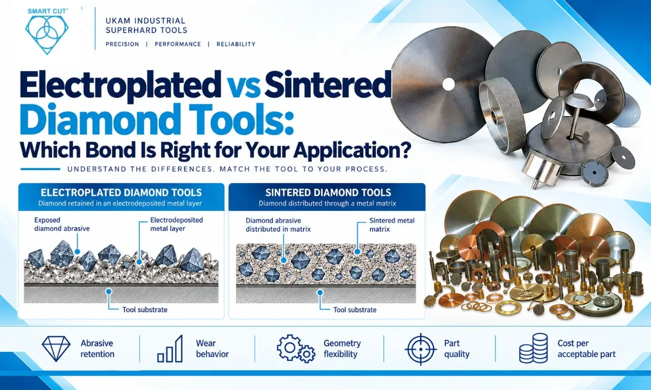
Table of Contents
Toggle
American Based Manufacturer

Established in 1990


Custom manufacturing


A diamond tool can lose cutting efficiency, damage a workpiece edge or drift outside dimensional tolerance even when its initial cutting performance appears satisfactory. In many production environments, the problem is not simply the diamond abrasive. It is the interaction between abrasive exposure, bond wear, workpiece properties, tool geometry and machine conditions.
Choosing between electroplated and sintered diamond tooling requires engineers to examine how the abrasive is retained, how the working surface changes during use and how the tool behaves as wear progresses. A lower purchase price does not automatically mean lower production cost. Similarly, a tool designed for continued abrasive exposure is not automatically the best choice for every material or operation.
The correct selection begins with the required part quality and production conditions, followed by a comparison of the actual tool construction and its measured performance.
When Should Engineers Reconsider the Bond?
Bond selection deserves review when the existing process shows a measurable change in performance.
Common warning signs include:
- Loss of cutting efficiency: Cycle time increases or the tool requires more force to complete the same operation.
- Glazing or rubbing: The working surface becomes less effective, potentially increasing heat and reducing material removal.
- Premature abrasive loss: The tool stops meeting process requirements before the expected production quantity is completed.
- Edge chipping or cracking: The operation produces unacceptable damage at entry, exit or along a machined surface.
- Dimensional drift: Tool wear, runout or geometry changes affect hole size, profile or another critical feature.
- Unstable production cost: Tool changes, downtime, inspection, rework or scrap increase the cost of acceptable output.
These symptoms do not prove that the bond is wrong. Poor workholding, spindle runout, inadequate coolant delivery, unsuitable feed, excessive engagement or inconsistent workpiece material can produce similar results.
Record the current process before changing the tool specification.
|
Parameter |
Required record |
|---|---|
|
Workpiece |
Material grade, composition, condition and thickness |
|
Operation |
Drilling, grinding, cutting, slotting or profiling |
|
Tool |
Construction, dimensions, grit specification and usable working area |
|
Machine |
Spindle condition, runout, stiffness and available power |
|
Process |
Speed, feed, depth of cut, coolant and tool path |
|
Quality |
Dimensional tolerance, surface finish and acceptable edge condition |
|
Production |
Cycle time, acceptable parts, tool changes, dressing and scrap |
|
Inspection |
Measurement method, sampling plan and acceptance limits |
This record gives the engineering team a defensible baseline for comparing alternative constructions.
Electroplated Diamond Tools: Surface Retention and Abrasive Exposure
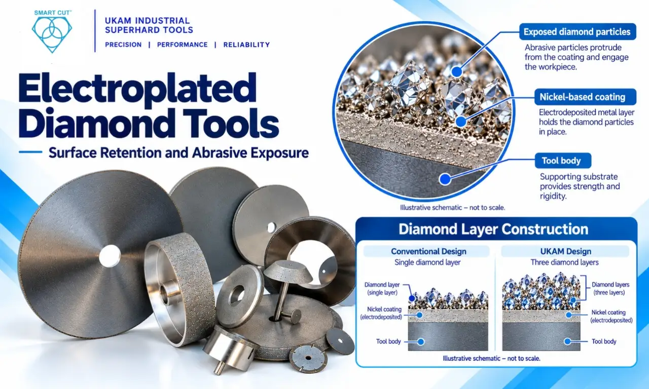
Electroplated diamond tools retain abrasive particles through an electrodeposited metal coating, commonly nickel based. The plating process holds exposed diamond particles on a supporting tool body. The abrasive protrusion, coating thickness, grit and tool geometry affect how the working surface engages the workpiece.
Conventional electroplated diamond tools usually have a single diamond layer. UKAM states that its electroplated diamond products use three diamond layers, rather than the single layer used in conventional designs. This is a UKAM-specific construction claim, not a description of every electroplated product on the market.
The practical implication is that engineers should verify the construction of the actual product before making assumptions about abrasive coverage or usable wear allowance. Do not treat all electroplated tools as interchangeable simply because they use nickel bond technology.
Electroplated tools can be considered when the application requires exposed abrasive, a specialized profile or a defined tool shape. UKAM identifies applications involving glass, ceramics, carbide, fiberglass reinforced plastics and other nonferrous materials in its electroplated tooling information. Actual suitability depends on the workpiece, grit, geometry, coating specification and operating conditions.
Potential advantages must be balanced against the working layer’s wear condition. When abrasive retention or coating integrity deteriorates, the tool may no longer maintain the required finish, dimensions or cutting behavior. The tool’s end of usable life should be defined by the application rather than by appearance alone.
Sintered Metal Bond Diamond Tools: Abrasive Embedded in a Matrix
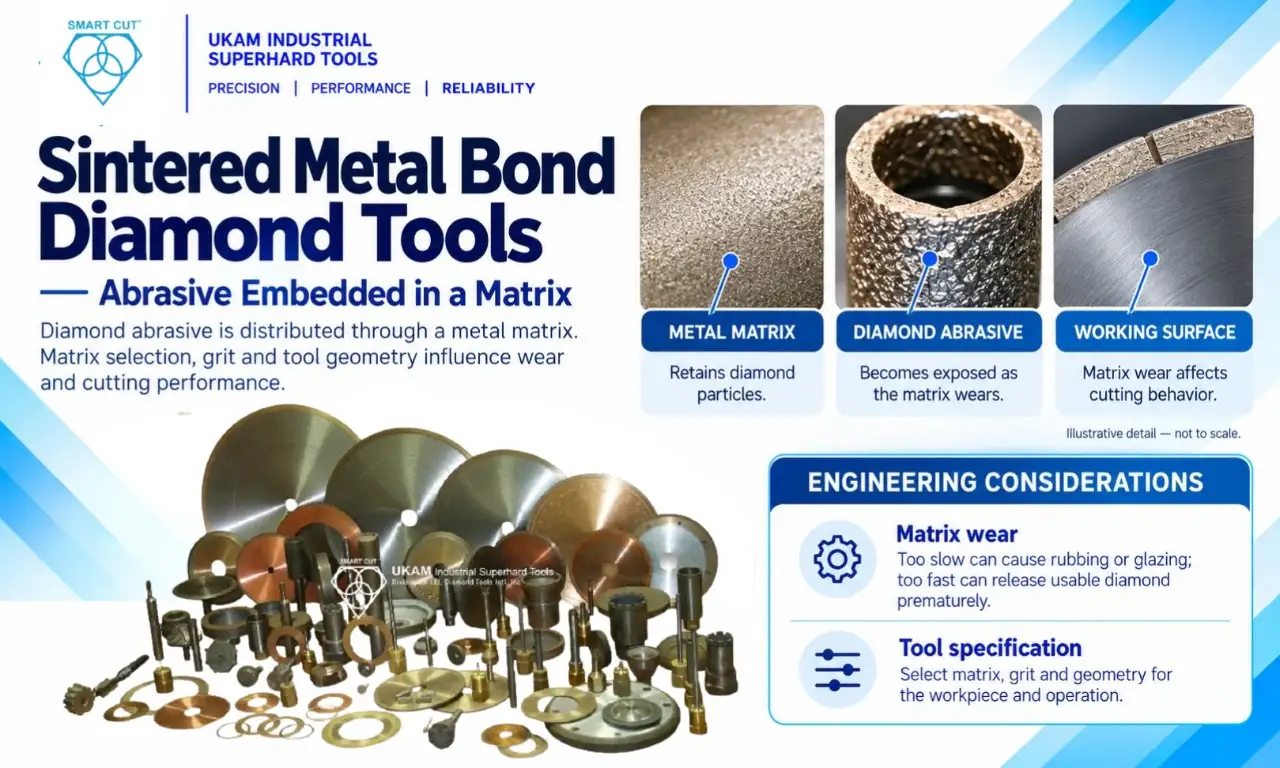
Sintered metal bond tools contain diamond abrasive distributed through a metal matrix. UKAM describes matrix materials that can include iron, cobalt, nickel, bronze, copper, tungsten and combinations of metal powders. The selected matrix and abrasive specification influence the tool’s behavior.
As the working matrix wears, additional diamond can become exposed. Continued cutting depends on the relationship between matrix wear, abrasive wear and the workpiece. A matrix that wears too slowly for the process can retain ineffective abrasive and contribute to rubbing or glazing. A matrix that wears too quickly can release usable diamond prematurely.
The term sintered metal bond therefore does not define one universal wear characteristic. Engineers need to consider the particular matrix composition, diamond grit, concentration, tool geometry and workpiece material.
UKAM lists sintered tools in several forms, including grinding wheels, cut-off wheels, dicing blades, drills, core drills, slotting tools and forming tools. The appropriate specification depends on the operation and required result, not solely on the bond family.
|
Selection factor |
Electroplated diamond |
Sintered metal bond diamond |
|---|---|---|
|
Abrasive retention |
Diamond retained in an electrodeposited metal layer |
Diamond distributed through a sintered metal matrix |
|
UKAM construction detail |
UKAM states its electroplated products use three diamond layers |
UKAM describes multiple diamond layers impregnated in the matrix |
|
Working surface |
Exposed abrasive cuts at the tool surface |
Matrix wear exposes additional abrasive |
|
Key wear question |
How does the working layer and abrasive retention change during use? |
|
|
Geometry consideration |
Evaluate plated dimensions, abrasive protrusion and profile accuracy |
Evaluate tool form, matrix specification and geometry retention |
|
Main qualification evidence |
Cutting behavior, dimensional stability, layer condition and usable output |
Cutting behavior, matrix wear, abrasive exposure and usable output |
|
Selection rule |
Confirm the specific construction and its limitations |
Confirm the matrix and abrasive specification for the operation |
Neither construction should be selected using a universal claim about speed or life. Compare the complete tool specification under equivalent production conditions.
Match the Tool Specification to the Application
Bond type is only one variable. Grit, concentration, abrasive exposure, matrix composition, tool geometry, machine condition and coolant can change the result.
|
Production requirement |
What to investigate |
What to measure |
|---|---|---|
|
Higher removal rate |
Grit, abrasive exposure, feed, speed and machine power |
Cycle time and removal rate |
|
Tight dimensional tolerance |
Runout, geometry, wear and mounting |
Dimensions at defined intervals |
|
Low edge damage |
Grit, workpiece support, entry and exit conditions |
Chip size, edge defects and cracks |
|
Fine surface finish |
Grit, abrasive exposure, process stability and finishing allowance |
|
|
Longer production runs |
Usable wear allowance and stability of cutting behavior |
Acceptable parts per tool |
|
Specialized profile |
Tool geometry, plating allowance or sintered form |
Profile measurement before and after use |
|
Lower production cost |
Tool consumption, downtime, finishing and rejected parts |
Cost per acceptable part |
Coarser diamond grit can support more aggressive abrasive engagement in suitable applications, but may create larger surface damage features. Finer grit may support a finer surface texture, but can become ineffective if abrasive exposure, feed or debris removal is inadequate.
Concentration affects the amount and distribution of abrasive in the working region. The result depends on the complete specification rather than one parameter in isolation. For electroplated tooling, the grit and coating thickness affect abrasive protrusion and chip clearance. For sintered tooling, matrix composition and wear behavior affect continued abrasive exposure. UKAM discusses coating thickness and abrasive exposure as part of its electroplated tooling information.
The best practice is to define the required surface finish and removal rate first, then request a complete tool specification. Change one major process variable at a time during qualification where practical.
Material-Specific Failure Modes
Material hardness alone does not determine bond suitability. Abrasiveness, brittleness, microstructure, workpiece thickness, edge support and inspection requirements must also be considered.
These are potential failure modes, not universal predictions. A tool trial should identify the cause of the defect before the specification is changed.
|
Material |
Failure mode to monitor |
Qualification priority |
|---|---|---|
|
Glazing, slow penetration, edge chipping or microcracking |
Cutting stability, matrix wear and subsurface damage |
|
|
Edge breakout, surface chipping or inconsistent removal |
Grit, feed, support and edge quality |
|
|
Silicon nitride |
Low removal rate, excessive load or surface damage |
Machine stiffness, tool condition and process stability |
|
Uneven wear, edge damage or dimensional variation |
Material grade, geometry and abrasive specification |
|
|
Edge chipping, cracking or surface defects |
Contact conditions, workpiece support and inspection |
|
|
Edge chips, cracks or localized damage |
Runout, engagement, coolant and exit conditions |
|
|
Entry or exit chipping and dimensional variation |
Support, feed, coolant and tool condition |
|
|
Brittle fracture, edge damage or surface defects |
Part support, low-damage processing and suitable handling |
|
|
PCD |
Cutting-edge chipping or inconsistent material removal |
Actual cutting geometry, substrate and inspection |
Ceramics and carbide
For silicon carbide, alumina, silicon nitride and tungsten carbide, investigate cutting behavior alongside edge quality and dimensional results. A slow process may indicate ineffective abrasive engagement, but it may also result from poor machine condition, unsuitable operating settings or inadequate coolant delivery. Increasing feed without diagnosing the cause can worsen edge damage or load.
Record the material grade and actual tool condition. Similar material names do not establish identical machining behavior.
Glass, quartz and sapphire
Brittle materials are sensitive to tool engagement, runout, workpiece support and edge formation. A tool that meets cycle time requirements but produces unacceptable chipping is not a successful production choice.
Define the inspection method before the trial. Where subsurface damage is critical, visual inspection alone may not be sufficient. The validation method must match the part specification and the consequences of a defect.
GaAs and PCD
GaAs and PCD applications require a specification tied to the actual operation. For GaAs, include fragility and appropriate handling controls. For PCD, distinguish between machining the material and processing a PCD tool’s cutting edge. Recommendations should not be transferred between these applications without technical review.
Compare Cost per Acceptable Part
The initial tool price does not capture the full production cost. A fair comparison accounts for tool consumption, machine time, dressing or conditioning, tool changes, inspection, finishing, scrap and rework when those costs are relevant.
No verified UKAM price, tool-life or production-cost figures are assumed in the following worksheet.
|
Metric |
Electroplated trial |
Sintered trial |
|---|---|---|
|
Tool price |
Enter actual quote |
Enter actual quote |
|
Started parts per tool |
Measure |
Measure |
|
Acceptable parts per tool |
Measure |
Measure |
|
Cycle time |
Measure |
Measure |
|
Tool change downtime |
Record |
Record |
|
Dressing or conditioning |
Record if applicable |
Record if applicable |
|
Scrap and rework |
Measure |
Measure |
|
Cost per acceptable part |
Calculate from actual data |
Calculate from actual data |
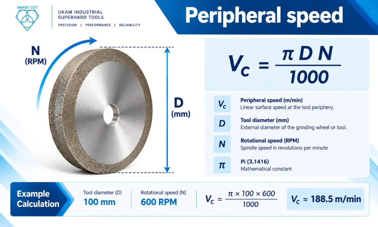
Formula 1: Peripheral speed
For tool diameter D in millimetres and rotational speed N in revolutions per minute:
Vc =π D N1000
where Vc is peripheral speed in metres per minute.
For example, a 10 mm tool at an illustrative peripheral speed of 15 m/min gives:
N =1000 (15)π (10) ≈ 477 RPM
This is a calculation example, not an operating recommendation for a UKAM product. Use the specific tool guidance and machine limits.
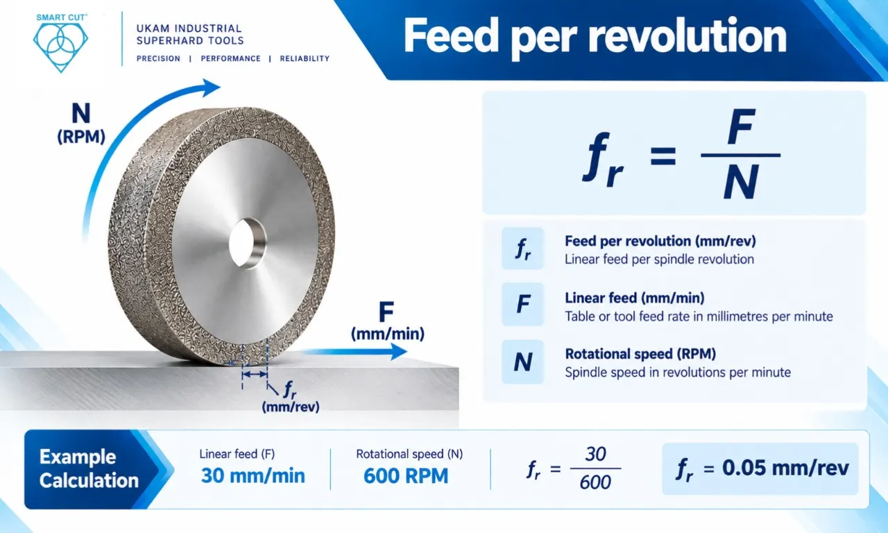
For linear feed F in millimetres per minute:
fr =FN
A feed of 30 mm/min at 600 RPM gives 0.05 mm/rev. This calculation helps document and compare operating conditions, but does not establish an optimal feed for a particular material.
Yield =Acceptable partsStarted parts
Include tool consumption, machine time, tool change downtime, inspection, finishing, scrap and rework as appropriate. Use the same accounting boundary for both trials. If the machine hourly rate already includes labor or overhead, do not add those same costs again separately.
A valid comparison requires equivalent parts, equivalent acceptance criteria and comparable operating conditions. A short trial may not represent normal tool wear or production variation, so record the limitations of the dataset.
Controlled Qualification in Seven Phases
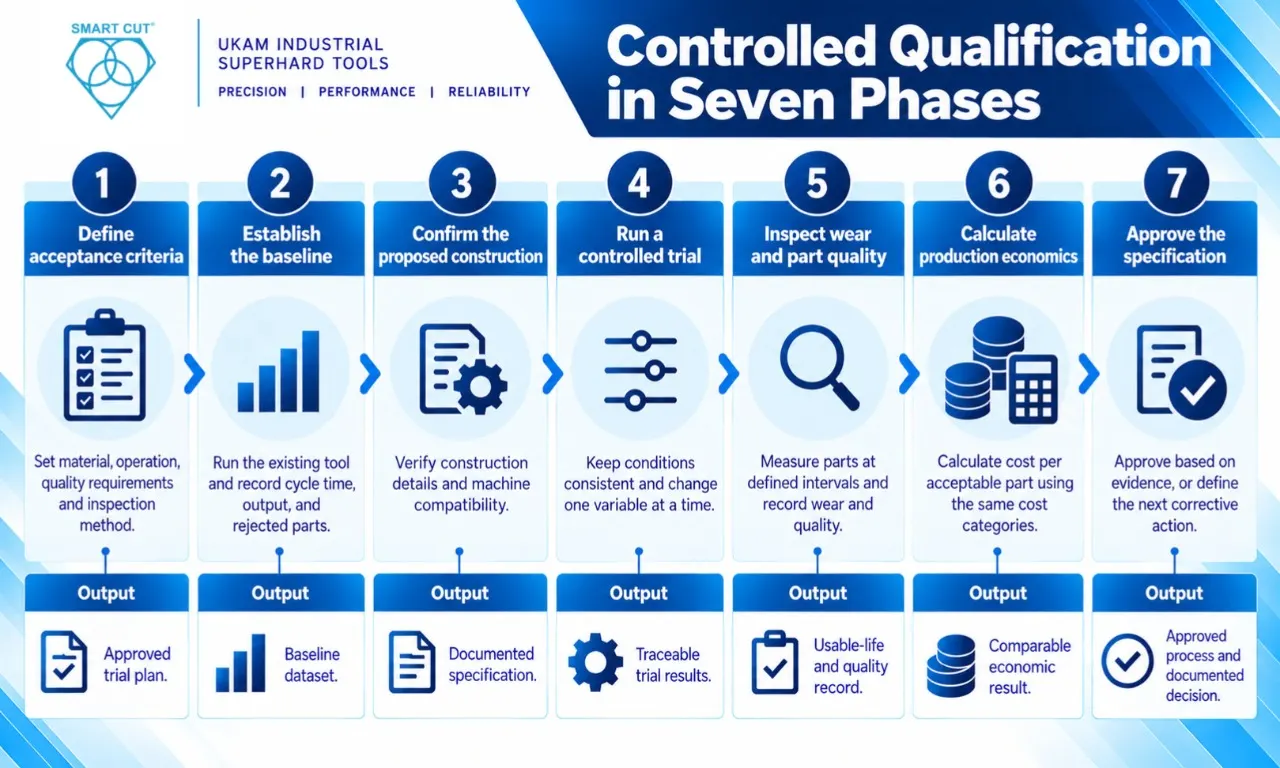
Phase 1: Define acceptance criteria
Document material grade, operation, critical dimensions, finish, edge quality, production volume and cycle time requirements. Define inspection methods and sampling frequency before the test begins.
Output: An approved trial plan with measurable pass or fail criteria.
Phase 2: Establish the baseline
Run the existing tool under recorded conditions. Measure cycle time, acceptable output, dimensional variation, tool changes, dressing and rejected parts. Record the tool’s condition.
Output: A baseline dataset.
Phase 3: Confirm the proposed construction
Request the tool’s construction, grit, concentration, matrix or coating details, geometry, operating limits and relevant limitations. Verify machine compatibility.
Output: A documented specification.
Phase 4: Run a controlled trial
Keep the workpiece, fixture, machine, coolant and inspection method consistent. Change one major variable at a time where practical, and record any deviations.
Output: Traceable trial results.
Phase 5: Inspect wear and part quality
Measure parts at defined intervals. Record dimensional drift, edge damage, surface defects, cutting behavior and replacement events.
Output: A usable-life and quality record.
Phase 6: Calculate production economics
Calculate cost per acceptable part using the same cost categories for each option. Include downtime and finishing costs where applicable.
Output: A comparable economic result based on measured data.
Phase 7: Approve the specification
Approve the tool only when the evidence shows that it meets quality and process limits. If the trial fails, identify the likely cause and plan the next controlled change.
Supplier Evaluation: Questions That Reveal Technical Capability
|
What to ask |
What the answer reveals |
|---|---|
|
What exact construction does this tool use? |
Whether the tool matches the intended abrasive retention system |
|
What grit, concentration and matrix or coating are recommended? |
Whether the recommendation addresses the application rather than only the material name |
|
What operating conditions apply to this exact tool? |
Whether the guidance is product specific |
|
What wear or failure modes should be monitored? |
Whether the supplier can support process diagnosis |
|
How should end of usable life be defined? |
Whether replacement can be based on measurable criteria |
|
Are quoted tool-life results from the same material and operation? |
Whether the comparison is relevant |
|
Whether geometry, mounting and tolerances are considered |
|
|
What inspection data would help refine the tool? |
Whether the recommendation can be improved using evidence |
A technically useful supplier recommendation should connect construction and operating conditions to the required part quality, not rely only on broad claims about life or cutting speed.
Where SMART CUT Fits
SMART CUT is a UKAM technology designation, not a third bond category that replaces electroplated and sintered construction.
UKAM describes SMART CUT in terms of abrasive orientation, exposure and an open bond design. The company also discusses this technology in relation to sintered metal bond products and multilayer electroplated products. The actual construction must be confirmed on the individual product page.
|
Verification point |
What to confirm |
|---|---|
|
Bond construction |
Electroplated, sintered or another specified construction |
|
SMART CUT designation |
Whether the exact product uses this technology |
|
Abrasive specification |
Diamond grit, concentration and relevant product details |
|
Geometry |
Dimensions, working area, mounting and tolerance |
|
Operating limits |
Recommended speed, feed, coolant and machine requirements |
|
Performance evidence |
Data relevant to the same material and operation |
For example, UKAM identifies the SMART CUT 030DSM as a sintered metal bond diamond solid drill. That product-specific description should not be applied to every SMART CUT tool. Verify the exact product specification before selecting it for a new application.
Pre-Production Qualification Checklist
Workpiece and quality
- Material grade and condition are documented.
- Edge damage limits and inspection methods are specified.
- Dimensional tolerances and surface finish are defined.
Tool and machine
- Tool construction, grit and relevant specification are confirmed.
- Geometry and mounting match the machine.
- Runout, workholding and support have been checked.
- Speed, feed and coolant requirements are documented.
Trial and economics
- Baseline data have been recorded.
- Trial conditions are traceable.
- Wear and part quality are checked at defined intervals.
- Acceptable output and usable tool life are measured.
- Cost per acceptable part uses a consistent accounting boundary.
Approval
- The tool meets the required part quality.
- Process stability has been assessed over a representative run.
- Product claims match the exact tool specification.
- The approved tool and operating conditions are documented.
Frequently Asked Questions
No. Cutting rate depends on abrasive specification, geometry, workpiece properties, machine condition and operating settings. Exposed abrasive may be advantageous in a suitable operation, but a general speed claim is not enough to select the tool. Compare cycle time and part quality under equivalent conditions.
No universal tool-life ranking applies to every application. Sintered tools contain abrasive within a metal matrix, and continued cutting depends on the relationship between matrix wear and abrasive exposure. Measure usable output and dimensional stability rather than assuming that construction alone guarantees longer life.
UKAM states that its electroplated diamond products have three diamond layers, while conventional electroplated products usually have a single diamond layer. This is a manufacturer-specific construction distinction. Confirm the actual product specification before comparing wear allowance or expected performance.
There is no single best matrix for all ceramics. UKAM describes sintered matrices made from combinations of metals such as iron, cobalt, nickel, bronze, copper and tungsten. The selection depends on the ceramic grade, operation, abrasive specification, machine capability and required finish.
Do not assume that they can. Dressing or conditioning requirements depend on the tool construction and manufacturer instructions. Confirm the approved method for the exact product before attempting to restore cutting action.
Define end of usable life using an application-specific criterion, such as failure to meet dimensional tolerance, unacceptable edge damage, excessive cycle time or a specified wear limit. Record acceptable parts, operating conditions and replacement events. A tool-life figure without its test conditions is not a reliable basis for selection.
Cost per acceptable part is often more informative than purchase price because it can account for tool consumption, machine time, downtime, finishing, scrap and rework. Use the same cost categories and acceptance criteria for each alternative.
No. SMART CUT is a UKAM technology designation. The bond construction depends on the specific product. Check the individual product page or specification rather than inferring the construction from the technology name.
Engineering Summary
- Select the tool against measurable part quality and production requirements.
- Compare the actual abrasive retention systems, not just the bond names.
- For UKAM electroplated tools, verify the stated three-layer construction and the specification of the selected product.
- For sintered tools, evaluate matrix composition, abrasive specification and wear behavior.
- Diagnose glazing, chipping and dimensional drift before changing the tool.
- Compare cost per acceptable part using actual production records and a consistent accounting boundary.
- Qualify the exact tool under controlled conditions before production approval.
- Treat SMART CUT as a technology designation and verify the construction of each product.
Trusted by Tens of Thousands of Manufacturers, Laboratories,
Research Institutions Worldwide Since 1990
American Based Manufacturer
Established in 1990
