Why the Same Diamond Blade Performs Differently on Different Machines, Materials, and Applications

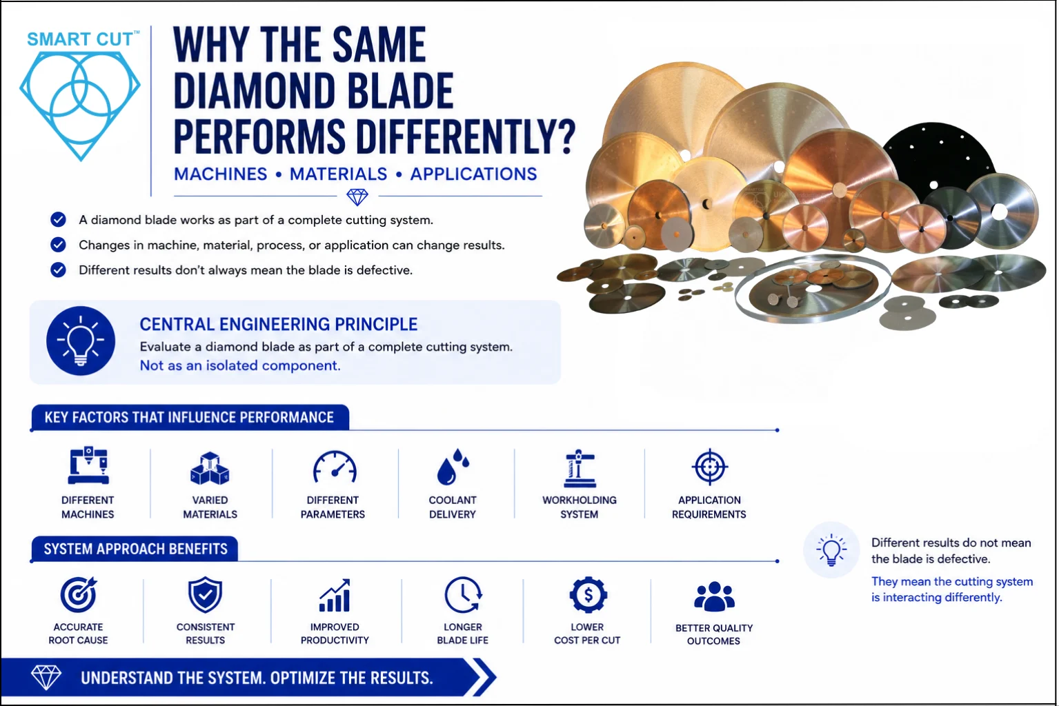
Table of Contents
ToggleA precision diamond blade does not operate independently of the cutting system around it. The blade is one component in a system that includes the machine, spindle, mounting hardware, workholding, material, cutting parameters, coolant, dressing condition, and the quality requirements of the application.
This is why the same diamond blade can produce an excellent cut on one machine and an unacceptable cut on another. The blade may also perform differently when the machine remains unchanged but the material grade, thickness, orientation, coating, or required edge quality changes.
Different results do not automatically mean that the blade is defective. They indicate that one or more parts of the cutting system are interacting differently.
Central engineering principle: Evaluate a diamond blade as part of a complete cutting system. Do not evaluate it as an isolated component.
This guide explains how machine condition, blade installation, material characteristics, cutting parameters, coolant delivery, workholding, and application requirements change diamond blade performance. It also provides a systematic method for determining whether a cutting problem originates from the blade, machine, material, or process.
Trusted by Tens of Thousands of Manufacturers, Laboratories Research Institutions Worldwide Since 1990

American Based Manufacturer

Established in 1990


Custom manufacturing


Why Diamond Blade Performance Cannot Be Evaluated in Isolation
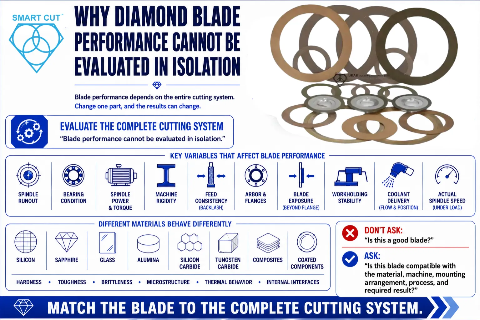
Diamond blades remove material through the combined action of the abrasive particles, the bond that holds those particles, the workpiece, and the forces generated by the cutting system. The blade must remain stable while the diamond abrasive penetrates, fractures, shears, or abrades the material.
During cutting, the blade experiences mechanical and thermal loading. The machine must maintain rotational accuracy, resist deflection, control the feed motion, support the workpiece, and deliver coolant to the cutting interface. The bond must retain the diamond particles long enough to cut effectively while allowing worn abrasive to be renewed at an appropriate rate.
If one part of this system changes, the cutting behavior can change even when the catalog blade specification remains the same.
For example, two machines may operate the same blade at the same programmed RPM and feed rate. Their results can still differ because of differences in:
• Spindle runout
• Bearing condition
• Spindle power and available torque
• Machine rigidity
• Axis backlash or feed consistency
• Arbor and flange condition
• Blade exposure beyond the flange
• Workholding stability
• Coolant flow and nozzle position
• Actual spindle speed under cutting load
The same principle applies when the blade moves from one material to another. Silicon, sapphire, glass, alumina, silicon carbide, tungsten carbide, composites, and coated components respond differently because their hardness, toughness, brittleness, microstructure, thermal behavior, and internal interfaces differ.
The correct question is not simply, “Is this a good blade?”
The correct question is, “Is this blade compatible with this material, machine, mounting arrangement, process, and required result?”
The Variables That Control Diamond Blade Performance
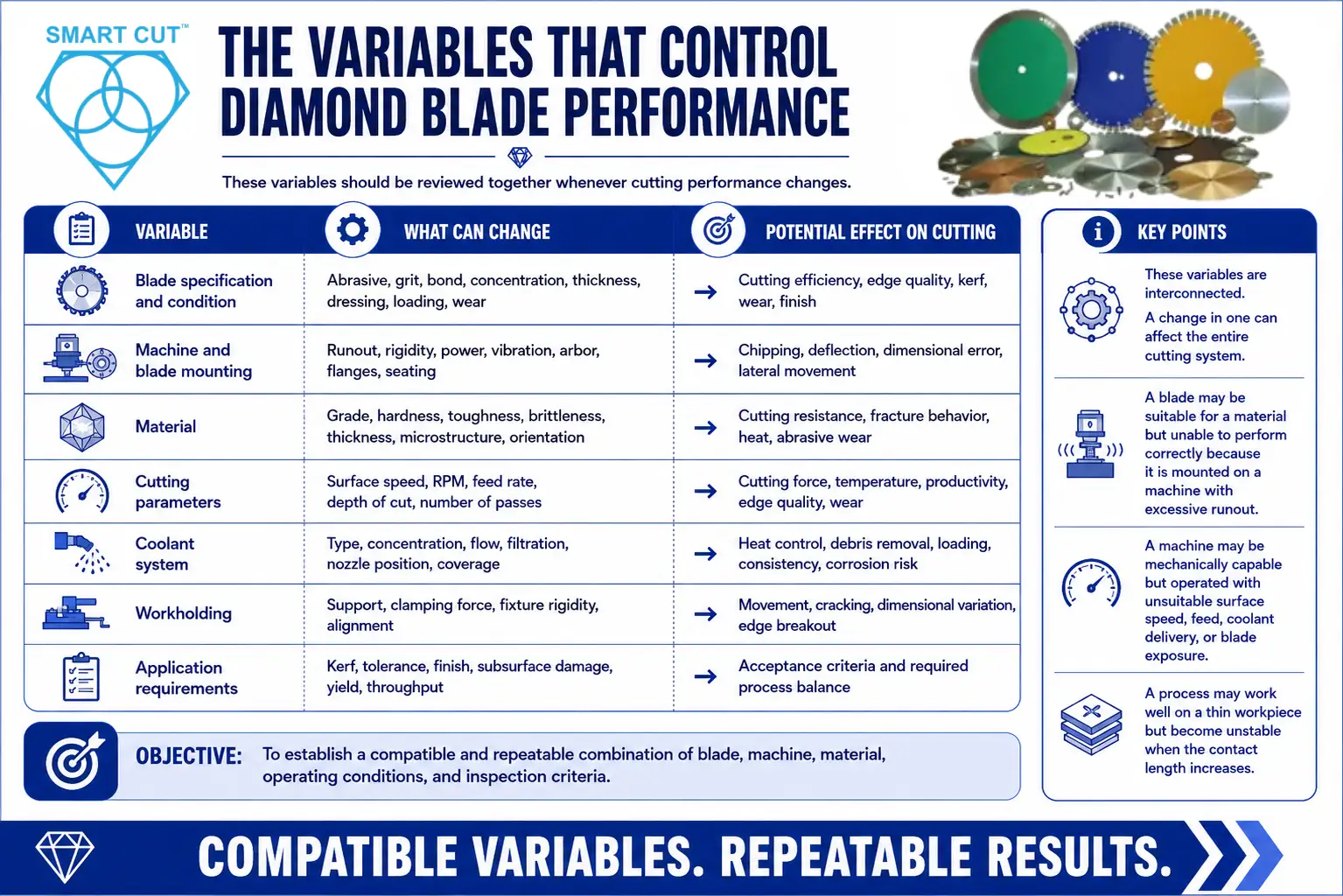
The following variables should be reviewed together whenever cutting performance changes.
| Variable | What can change | Potential effect on cutting |
|---|---|---|
| Blade specification and condition | Abrasive, grit, bond, concentration, thickness, dressing, loading, wear | Cutting efficiency, edge quality, kerf, wear, finish |
| Machine and blade mounting | Runout, rigidity, power, vibration, arbor, flanges, seating | Chipping, deflection, dimensional error, lateral movement |
| Material | Grade, hardness, toughness, brittleness, thickness, microstructure, orientation | Cutting resistance, fracture behavior, heat, abrasive wear |
| Cutting parameters | Surface speed, RPM, feed rate, depth of cut, number of passes | Cutting force, temperature, productivity, edge quality, wear |
| Coolant system | Type, concentration, flow, filtration, nozzle position, coverage | Heat control, debris removal, loading, consistency, corrosion risk |
| Workholding | Support, clamping force, fixture rigidity, alignment | Movement, cracking, dimensional variation, edge breakout |
| Application requirements | Kerf, tolerance, finish, subsurface damage, yield, throughput | Acceptance criteria and required process balance |
These variables are interconnected. A blade may be suitable for a material but unable to perform correctly because it is mounted on a machine with excessive runout. A machine may be mechanically capable but operated with unsuitable surface speed, feed, coolant delivery, or blade exposure. A process may work well on a thin workpiece but become unstable when the contact length increases.
The objective is to establish a compatible and repeatable combination of blade, machine, material, operating conditions, and inspection criteria.
How the Machine Changes Diamond Blade Performance
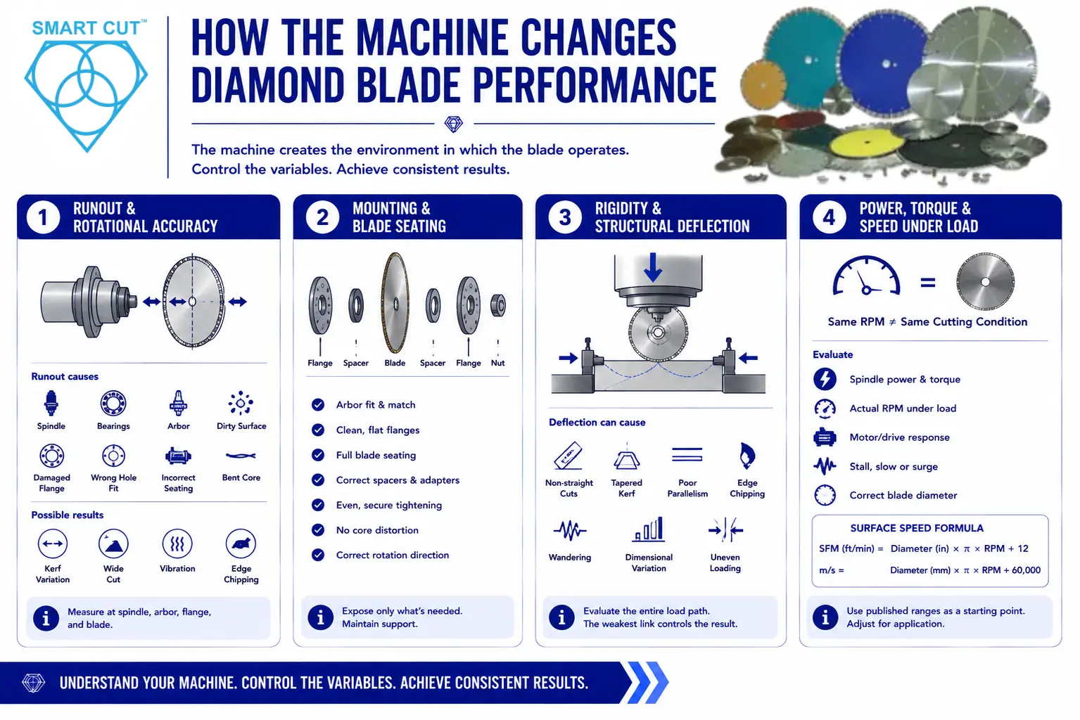
The machine provides the mechanical environment in which the blade operates. Even a properly selected precision blade cannot fully compensate for excessive runout, poor blade mounting, weak workholding, inconsistent feed motion, inadequate coolant delivery, or structural vibration.
When the same blade performs differently on two machines, the machine-side variables should be investigated before the blade is rejected.
Spindle Runout and Rotational Accuracy
Spindle runout describes unwanted deviation from the intended axis of rotation. In precision sectioning, the blade must rotate around a stable axis to maintain a consistent cutting path.
Runout can originate from several locations:
• The spindle itself
• Worn or damaged bearings
• The arbor or adapter
• Dirt, corrosion, or burrs on a mounting surface
• A damaged or distorted flange
• An arbor hole that does not fit correctly
• Incorrect blade seating
• A blade core that has been bent or damaged
Excessive runout can create lateral movement at the blade rim. The effect at the cutting edge may be greater than the deviation measured near the spindle because the blade diameter magnifies angular or mounting errors.
Possible results include:
• Kerf variation
• An unexpectedly wide cut
• Side loading
• Edge chipping
• Vibration
• Uneven blade wear
• Poor parallelism
• Reduced dimensional control
Runout should be measured systematically. A useful inspection separates the spindle, arbor, flange, and installed blade rather than measuring only one location. The measurement method should also be consistent between machines. A reading taken at the arbor cannot be compared directly with a reading taken near the blade periphery without accounting for the measurement location.
Acceptable runout depends on the blade diameter, blade thickness, construction, required kerf, and dimensional tolerance. Thin blades and applications with tight kerf requirements are generally more sensitive to lateral movement. A single universal runout limit should not be applied to every blade and machine.
Arbor Fit, Flange Condition, and Blade Seating
Blade mounting is part of the cutting system. A high-quality blade can perform poorly when the mounting surfaces do not support it correctly.
Before installation, inspect the arbor, flanges, spacers, and blade core. Mounting surfaces should be clean, flat, undamaged, and free of particles that can prevent full contact. A small chip, burr, or layer of dried coolant trapped behind a flange can introduce measurable lateral error at the blade rim.
Check the following:
• The blade arbor matches the machine arbor or approved adapter.
• The arbor fit provides concentric location without forcing the blade onto the spindle.
• Both flanges are clean and flat.
• Flange contact surfaces are free of corrosion, damage, and embedded debris.
• The flanges are appropriate for the blade diameter and thickness.
• The blade seats fully against the mounting surface.
• Spacers and adapters are correctly installed.
• The blade is tightened evenly and securely.
• Tightening does not distort the blade core.
• The blade rotation direction is correct when the blade design requires a specific direction.
Flange diameter also matters. Larger, properly matched flanges provide more lateral support and reduce the unsupported blade area. However, the flanges must leave enough cutting exposure for the required depth of cut. Excessive blade exposure can reduce lateral stability, especially with ultra-thin blades.
The goal is not to expose the largest possible portion of the blade. The goal is to expose only what the application requires while maintaining adequate support.
Machine Rigidity and Structural Deflection
Machine rigidity determines how effectively the cutting system resists movement under load. As the blade enters the material, cutting resistance acts on the blade, spindle, feed system, fixture, and workpiece.
If these components deflect, the blade may move away from its intended path. The operator may see:
• Non-straight cuts
• Tapered or uneven kerf
• Poor parallelism
• Edge chipping
• Blade wandering
• Dimensional variation
• Uneven loading on the blade sides
Rigidity becomes especially important when cutting thick sections, hard materials, brittle ceramics, long contact lengths, or workpieces that require a deep cut. A blade that performs well on a rigid precision saw may not provide the same result on a machine with greater spindle movement, frame deflection, or fixture compliance.
Machine rigidity should be considered as a complete load path. The frame may be rigid while the spindle mount, sliding axis, fixture, or workpiece support remains flexible. The weakest part of the load path can control the result.
Spindle Power, Torque, and Speed Under Load
Two machines can display the same programmed RPM but behave differently during cutting. One spindle may maintain its speed under load while another slows when the blade enters the material.
Loss of speed changes the effective cutting condition. It can increase chip load on the available abrasive, raise cutting force, reduce debris evacuation, and contribute to loading or heat generation.
Evaluate:
• Rated spindle power
• Available torque within the operating-speed range
• Actual RPM during the cut
• Motor or drive response to changing load
• Whether the machine stalls, slows, or surges
• Whether the selected blade diameter is appropriate for the machine
The relationship between RPM and blade diameter should be expressed as peripheral or surface speed when comparing different blade sizes. The same RPM applied to a 4-inch blade and a 12-inch blade does not produce the same cutting-edge speed.
Surface speed can be calculated as:
Surface speed in feet per minute = blade diameter in inches × π × RPM ÷ 12
Surface speed in meters per second = blade diameter in millimeters × π × RPM ÷ 60,000
Published operating recommendations should be treated as application-specific starting ranges. The final setting must account for the blade construction, diameter, material, contact length, machine capability, coolant, and required result.
Feed Control and Motion Quality
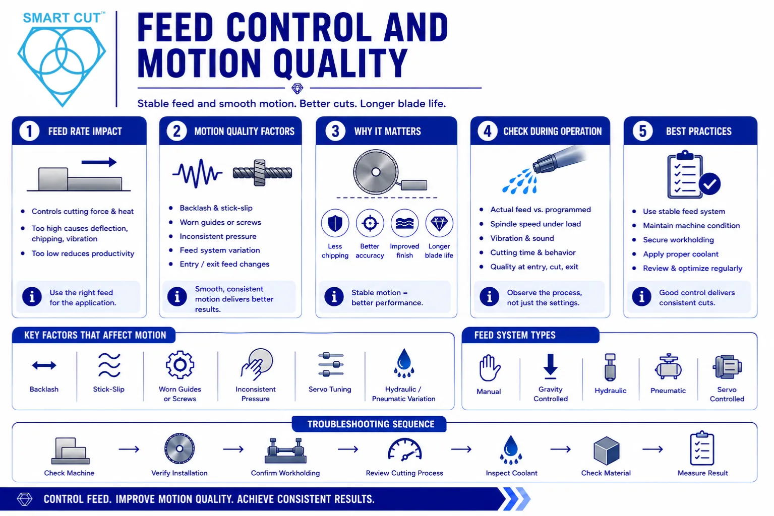
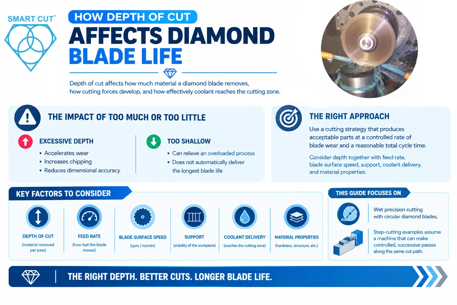
Feed rate controls how quickly the blade advances through the workpiece. It influences cutting force, abrasive engagement, heat generation, and productivity.
An excessive feed demand can cause:
• Blade deflection
• Increased edge chipping
• Higher vibration
• Slower spindle speed under load
• Increased thermal loading
• Poor surface finish
• Accelerated or uneven blade wear
However, simply reducing feed rate is not always the correct solution. An extremely slow feed may reduce productivity without correcting runout, poor mounting, unstable workholding, inadequate coolant, or an unsuitable blade specification.
Feed quality also matters. Two machines programmed for the same nominal feed rate may not produce the same motion. Differences can result from:
• Axis backlash
• Stick-slip movement
• Worn guides or screws
• Inconsistent manual pressure
• Servo tuning
• Hydraulic or pneumatic feed variation
• Changes in feed rate during entry and exit
For controlled testing, record whether the feed is manual, gravity-controlled, hydraulic, pneumatic, or servo-controlled. When possible, compare the actual cutting time and observed feed behavior, not only the programmed value.
Vibration, Resonance, and Bearing Condition
Vibration changes the contact between the blade and the workpiece. Instead of maintaining a stable abrasive interaction, the blade may repeatedly enter and leave the cutting interface or experience alternating lateral loads.
Vibration can originate from:
• Spindle imbalance
• Bearing wear
• A damaged blade core
• Improper blade mounting
• Uneven flanges
• Machine-frame resonance
• Loose guards or fixtures
• Workpiece movement
• Interrupted or layered material
• Unsuitable cutting parameters
Potential results include:
• Intermittent cutting marks
• Repeating edge chips
• Surface waviness
• Kerf variation
• Noise changes
• Increased blade wear
• Localized damage at particular positions in the cut
The distribution of damage can provide useful evidence. Random chipping may suggest a different problem from regularly spaced marks. Damage concentrated near entry or exit may point toward workpiece support, cutting direction, or feed transitions. Damage appearing only at a particular depth may indicate a change in material structure, coolant access, or system resonance.
Workholding and Workpiece Support
The workpiece must remain stable throughout the cutting operation. Poor workholding can create movement that appears to be a blade defect.
If the material shifts, lifts, twists, or vibrates during cutting, the blade can experience changing lateral forces. Possible results include:
• Blade wandering
• Irregular kerf
• Edge chipping
• Localized cracking
• Poor dimensional accuracy
• Blade damage
Workholding is particularly important for:
• Thin wafers
• Small components
• Fragile ceramics
• Laminated composites
• Coated materials
• Hollow parts
• Irregularly shaped specimens
• Components with limited clamping area
The fixture should provide adequate support without introducing unnecessary stress. Excessive clamping force can crack brittle material before cutting begins or store stress that is released as the cut progresses.
Support near the exit side can also affect edge breakout. A workpiece that becomes unsupported near the end of the cut may fracture before the blade completes material removal. This damage can be incorrectly attributed to the blade grit or bond.
Coolant Delivery, Coverage, and Filtration
Coolant does more than control temperature. It also lubricates the cutting interface where applicable, transports debris away from the blade, helps prevent loading, and improves process consistency.
Two machines using the same coolant product and concentration can produce different results because their delivery systems are different.
Evaluate:
• Coolant type
• Coolant concentration
• Flow rate
• Nozzle position
• Coverage on both sides of the blade when possible
• Whether coolant reaches the blade and workpiece contact zone
• Tank cleanliness
• Filtration quality
• Recirculation temperature
• Foam, biological contamination, or excessive debris
High flow at the wrong location may be less effective than controlled flow directed into the cutting interface. A nozzle aimed at the blade guard or blade surface far from the cut may not provide adequate cooling and debris removal where it is needed.
Insufficient or inconsistent coolant delivery can contribute to:
• Material burning or discoloration
• Resin smearing
• Blade loading
• Increased cutting resistance
• Reduced surface quality
• Thermal cracking
• Shortened blade life
• Unstable results from one cut to the next
Filtration should match the application. Recirculated abrasive particles and workpiece debris can scratch the cut surface, enter the kerf, interfere with the blade, and make it difficult to determine whether observed damage originated from the blade or contaminated coolant.
For more information, review UKAM’s guide to selecting the right coolant and coolant-delivery method.
Blade Dressing and Conditioning
Blade condition can change even when the blade specification remains unchanged. A new blade, a properly conditioned blade, and a loaded or glazed blade may behave very differently.
Dressing or conditioning may be needed to:
• Expose fresh abrasive
• Remove loaded workpiece material
• Restore cutting efficiency
• Improve coolant access to the cutting zone
• Stabilize the blade before qualification testing
The correct conditioning method depends on the blade bond, construction, application, and manufacturer recommendations. Excessive or unsuitable dressing can also shorten blade life or alter the cutting edge.
When comparing machines or materials, record:
• Whether the blade was dressed before testing
• The dressing material and method
• Dressing time or number of passes
• The number of cuts since dressing
• Whether cutting resistance changed during the test
A used blade should not be compared with a new blade without accounting for condition. Likewise, a freshly dressed blade should not be compared with a loaded blade and treated as an equivalent test.
Why Identical Machine Settings May Not Be Equivalent
Machine screens can create the impression that two processes are identical because both show the same RPM and feed rate. The real cutting conditions may still differ.
The following should be verified:
• Actual blade diameter
• Actual spindle speed under load
• Surface speed at the blade rim
• Actual cutting time through the material
• Feed behavior during entry, full engagement, and exit
• Blade exposure beyond the flange
• Coolant flow at the cutting interface
• Workpiece support and fixture stiffness
• Number of previous cuts on the blade
• Blade dressing condition
This explains why transferring settings from one machine to another should be treated as a starting point, not as proof that the processes are equivalent.
How to Troubleshoot a Machine-to-Machine Difference
When the same blade produces different results after being transferred to another machine, use a controlled comparison.
Machine
• Measure spindle and installed-blade runout using a consistent method.
• Inspect bearing condition, vibration, and unusual noise.
• Confirm that the spindle maintains speed under load.
• Review machine rigidity and feed-system condition.
Blade installation
• Clean and inspect the arbor, flanges, spacers, and blade core.
• Confirm correct seating and rotation direction.
• Verify that blade exposure is appropriate for the cut depth.
• Confirm that tightening does not distort the core.
Workholding
• Confirm fixture rigidity and workpiece support.
• Check for movement during entry and exit.
• Verify that clamping does not introduce stress.
Cutting process
• Record surface speed, RPM, feed rate, depth of cut, and number of passes.
• Compare actual cutting time.
• Verify coolant type, concentration, flow, filtration, and nozzle position.
• Record blade dressing condition.
Material
• Confirm grade, thickness, geometry, orientation, coating, and lot.
• Use comparable specimens whenever possible.
Result
• Measure kerf, edge chipping, dimensional accuracy, surface condition, and cutting time using the same inspection method.
• Photograph entry, full-cut, and exit conditions when the damage pattern matters.
Illustrative Machine-to-Machine Example
Consider an illustrative case in which the same thin precision diamond blade cuts the same ceramic material on two machines.
Machine A produces a straight cut with limited edge chipping. Machine B produces a wider and less consistent kerf with repeated chips along one edge.
Changing the blade immediately would not identify the cause. A controlled inspection could reveal that Machine B has contamination behind one flange, greater installed-blade runout, and coolant reaching only one side of the cut. Correcting the mounting and coolant delivery could improve the result without changing the blade specification.
The purpose of this example is not to suggest that every machine-to-machine problem has the same cause. It shows why the blade should be evaluated within the mechanical system before being classified as defective.
Do Not Change Multiple Variables at Once
A common troubleshooting mistake is changing the blade, feed rate, spindle speed, coolant, and fixture at the same time.
If the result improves, the engineer cannot determine which change solved the problem. If the result becomes worse, the source of the new problem is equally unclear.
Where practical, change one significant variable at a time. Record the starting condition, process change, and measured response.
Controlled troubleshooting sequence: Baseline condition → one controlled change → measured cutting response → documented conclusion
How Material and Application Requirements Change Blade Performance
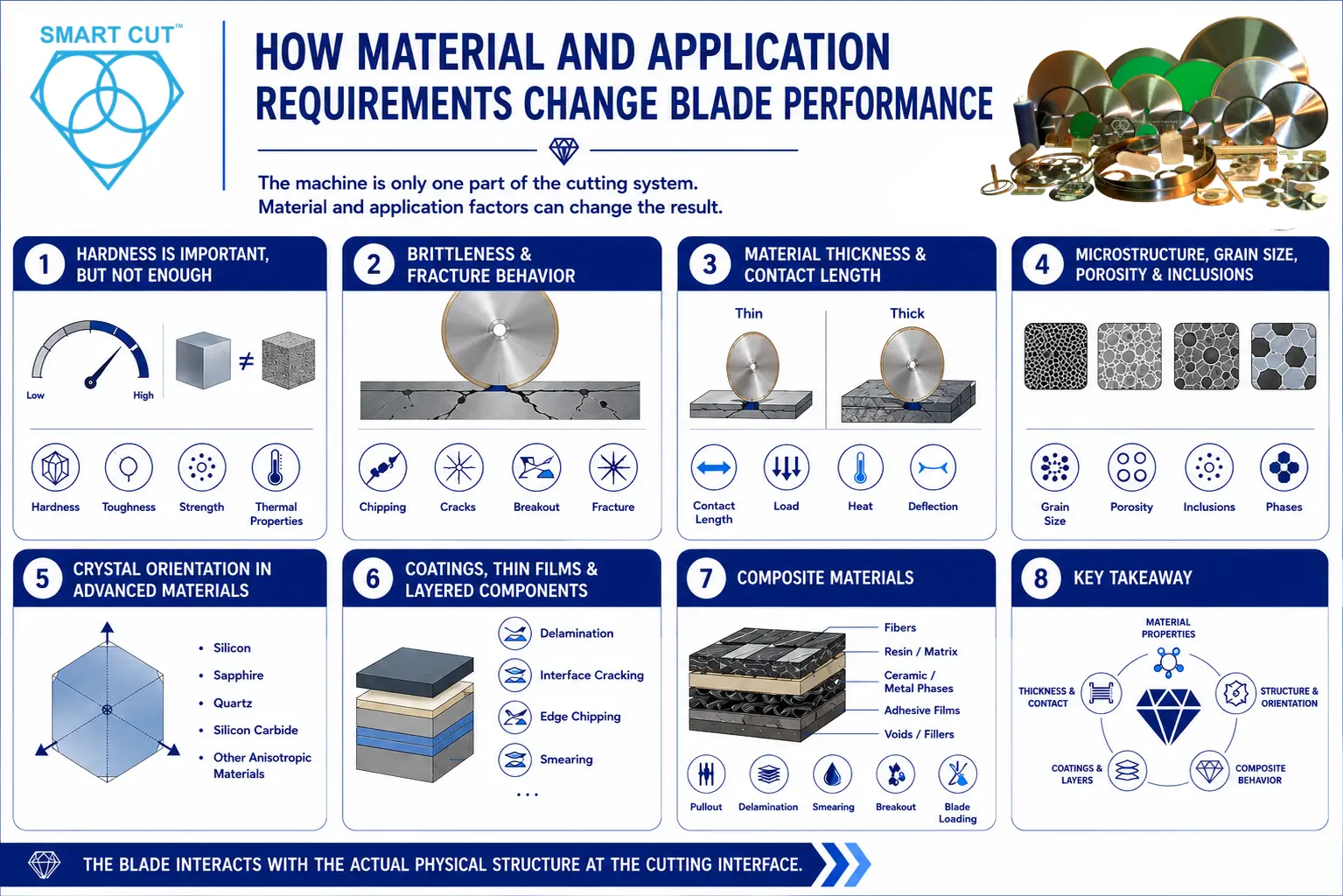
The machine is only one part of the cutting system. Even when the blade and machine remain unchanged, the cutting result can change because the material or application has changed.
Two workpieces may appear similar but respond differently because of differences in hardness, fracture toughness, brittleness, grain structure, porosity, thickness, coating, internal stress, crystal orientation, or thermal sensitivity.
The blade is not interacting with a material name. It is interacting with the actual physical structure presented at the cutting interface.
Hardness Is Important, but It Is Not Enough
Hardness influences how readily the diamond abrasive penetrates and removes material. Hard materials can place substantial demands on the abrasive system and may require a different balance of grit size, bond behavior, diamond concentration, surface speed, feed, and coolant.
However, hardness alone does not predict cutting behavior.
Two materials with similar hardness can produce different results because they have different:
- Fracture toughness
- Brittleness
- Grain structure
- Porosity
- Thermal conductivity
- Coefficient of thermal expansion
- Chemical composition
- Internal stress
Blade selection should therefore be based on the complete application, not on a single hardness value.
Material family also matters. Diamond is generally well suited for many nonferrous, abrasive, and hard brittle materials. For hardened ferrous materials, CBN may be more appropriate because diamond can experience accelerated chemical wear at elevated cutting temperatures when interacting with iron-based materials. The final abrasive selection should account for the specific alloy, operation, temperature, and process requirements.
Brittleness and Fracture Behavior
Brittle materials can crack instead of deforming when the cutting load exceeds their local fracture resistance. Cracks can initiate at the cutting edge and extend beyond the intended kerf.
Possible results include:
- Edge chipping
- Microcracking
- Subsurface damage
- Exit breakout
- Fracture propagation
- Complete part breakage
Materials such as glass, silicon, sapphire, alumina, silicon carbide, quartz, and many advanced ceramics can be particularly sensitive to changing mechanical loads.
Reducing unnecessary cutting force is important, but a lower feed rate is not automatically the complete solution. Runout, vibration, poor support, dull abrasive, excessive blade exposure, inadequate coolant, and unsuitable blade construction can all contribute to fracture.
The location and pattern of damage should be documented. Entry chipping, continuous edge damage, isolated mid-cut damage, and exit breakout may have different causes.
Material Thickness and Contact Length
The same blade cutting a thin section may experience a very different load from the same blade cutting a thicker section of the same material.
As material thickness or blade engagement increases, the process can experience changes in:
- Contact length
- Number of abrasive particles engaged
- Cutting resistance
- Heat generation
- Debris-removal demand
- Coolant access
- Blade deflection
- Cutting time
Parameters that work on a thin specimen should not automatically be transferred to a thick workpiece. A thicker section may require a different feed strategy, cutting depth, number of passes, coolant arrangement, blade thickness, bond, or machine configuration.
Thickness should always be recorded during blade qualification. The term “same material” is not sufficient if the contact length has changed substantially.
Microstructure, Grain Size, Porosity, and Inclusions
Nominal composition does not fully describe cutting behavior. The internal structure of a material can influence how the cutting force is transmitted and how cracks initiate.
Relevant variables may include:
- Grain size
- Grain distribution
- Porosity
- Voids
- Inclusions
- Phase composition
- Heat treatment
- Sintering condition
- Reinforcement distribution
A dense fine-grained ceramic may not cut the same way as a more porous or coarse-grained ceramic with a similar chemical composition. An inclusion can locally change cutting resistance and redirect a crack. A sintered part may have density variation from one region to another.
When unexplained performance changes appear, confirm whether the test specimens came from the same material lot, production condition, or region of the component.
Crystal Orientation in Advanced Materials
Some crystalline materials do not respond identically in every cutting direction. The relationship between the cut direction and the crystal structure can influence crack initiation, edge quality, and subsurface damage.
This can be relevant for:
- Silicon wafers
- Sapphire
- Quartz
- Silicon carbide
- Single-crystal ceramics
- Other anisotropic materials
If two specimens are cut in different orientations, differences in chipping may be incorrectly attributed to the blade. Controlled comparisons should maintain the same orientation whenever orientation is relevant to the material and application.
The orientation should be documented rather than described only as “the same material.”
Coatings, Thin Films, and Layered Components
Coated and layered components introduce multiple interfaces. The blade may pass through materials with substantially different hardness, toughness, adhesion, and thermal behavior.
A component may contain:
- Protective coatings
- Hard coatings
- Plated layers
- Thin films
- Thermal barriers
- Adhesive layers
- Polymer layers
- Ceramic-to-metal interfaces
- Bonded assemblies
As the blade crosses an interface, the cutting mechanism and local force can change. Possible results include:
- Coating delamination
- Interface cracking
- Edge chipping
- Uneven material removal
- Smearing of a soft layer
- Pullout of a brittle layer
- Changes in cutting resistance
A blade that performs well on the substrate alone may not provide the same result when the full material stack is present. The coating type, thickness, adhesion, layer order, and required inspection surface should be included in the application description.
Composite Materials
Composite materials can be challenging because their constituents respond differently to the same cutting action.
A composite may contain combinations of:
- Glass, carbon, ceramic, or polymer fibers
- Resin
- Ceramic phases
- Metallic phases
- Adhesive films
- Laminated structures
- Voids and fillers
Potential cutting problems include:
- Fiber pullout
- Delamination
- Resin smearing
- Edge breakout
- Matrix cracking
- Uneven surface finish
- Loading of the blade
Fiber orientation and cut direction can materially affect the result. A transverse cut may produce a different edge from a cut parallel to the fibers. A different layup sequence may also change the support available to each layer as the blade exits the material.
One composite test should not automatically be treated as representative of another composite with a different resin, fiber, orientation, or layup.
Thermal Sensitivity and Heat-Affected Damage
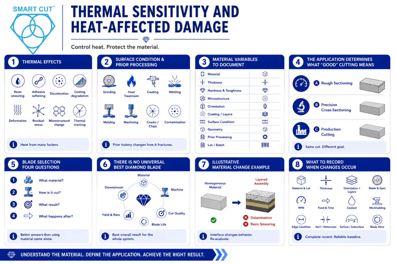
Some materials tolerate thermal input better than others. Polymers, resins, adhesives, coatings, and certain microstructures may soften, smear, discolor, deform, or degrade when heat accumulates at the cutting interface.
Thermal effects can include:
- Resin smearing
- Adhesive softening
- Surface discoloration
- Coating degradation
- Thermal deformation
- Residual stress
- Microstructural change
- Thermally assisted cracking
Thermal damage is influenced by more than coolant temperature. Cutting force, blade sharpness, surface speed, contact length, feed, coolant access, and debris evacuation all affect heat generation and removal.
If a material is thermally sensitive, the evaluation should include both visible cut quality and any downstream evidence of heat damage.
Surface Condition, Residual Stress, and Prior Processing
The workpiece may contain damage or stress before cutting begins. Grinding marks, heat treatment, coating processes, molding stresses, machining damage, and handling damage can influence how the part fractures during sectioning.
Record relevant prior processing such as:
- Grinding or polishing
- Heat treatment
- Coating or plating
- Welding or brazing
- Molding or curing
- Prior machining
- Existing cracks or chips
- Surface contamination
If two specimens have different prior histories, the same blade may reveal different damage even when their nominal material grades are identical.
Material Variables to Document
| Material Variable | What to Document |
|---|---|
| Material Identity | Exact material, grade, specification, or composition |
| Thickness | Actual thickness and maximum blade engagement |
| Hardness and Toughness | Available specification or measured result |
| Microstructure | Grain, phase, porosity, reinforcement, or structural condition |
| Orientation | Crystal, fiber, rolling, or cutting orientation where relevant |
| Coating or Layers | Material, thickness, sequence, and interface information |
| Surface Condition | Existing finish, contamination, damage, or coating condition |
| Geometry | Workpiece dimensions, shape, and unsupported features |
| Prior Processing | Heat treatment, molding, curing, grinding, welding, or coating |
| Lot or Batch | Material lot, production batch, or specimen source |
This information becomes particularly important when results appear inconsistent. A material change can alter cutting performance even when the blade and machine remain unchanged.
The Application Determines What “Good” Cutting Means
The required result depends on what happens after cutting. One application may prioritize maximum throughput while another prioritizes minimal edge damage, narrow kerf, low subsurface damage, or reduced polishing.
The same cut may therefore be acceptable for one application and unacceptable for another.
Application A: Rough sectioning
The objective is to separate material quickly before heavy grinding or machining. The process may tolerate more chipping, surface damage, and material loss if the remaining component stays usable.
Application B: Precision cross-sectioning
The cut is intended for microscopy, failure analysis, dimensional evaluation, or final inspection. The application may require minimal edge chipping, low subsurface damage, controlled kerf, good flatness, and limited polishing.
Application C: Production cutting
The objective may require a controlled balance of throughput, yield, blade life, dimensional consistency, automation, and downstream processing time.
The same blade should not be judged by the same single criterion in all three applications.
Blade Selection Should Begin With Four Questions
1. What material is being cut?
Identify the exact material, grade, hardness, brittleness, thickness, microstructure, orientation, coating, and geometry.
2. How is the material being cut?
Identify the machine, spindle, arbor, flanges, feed system, coolant system, workholding, cutting direction, and required cut depth.
3. What result is required?
Define the acceptable edge chipping, kerf, dimensional tolerance, surface condition, flatness, subsurface damage, material loss, and cutting time.
4. What happens after cutting?
Consider grinding, polishing, microscopy, failure analysis, assembly, coating, further machining, or direct use.
These questions provide a more reliable basis for blade selection than asking only which blade is suitable for a material name.
There Is No Universal Best Diamond Blade
A blade that provides excellent life in one application may not provide the lowest chipping in another. A blade that cuts quickly may create additional polishing work. A blade that minimizes kerf may require a more rigid machine and more precise mounting.
The appropriate blade is the one that produces the best overall result for the specific combination of:
- Material
- Machine
- Workpiece geometry
- Required cut quality
- Production rate
- Material yield
- Blade life
- Downstream processing
- Total process cost
This is why application-specific evaluation is often more reliable than selecting a blade solely from a catalog description or price.
Illustrative Material-Change Example
Consider a blade that produces an acceptable cut through a dense ceramic substrate. The same blade is then used on a coated assembly containing a brittle ceramic layer, adhesive, and polymer backing.
The operator observes coating delamination and resin smearing. This does not prove that the blade has failed. The cutting interface has changed from one homogeneous material to a layered system with different fracture and thermal behavior.
The next test should evaluate coolant access, surface speed, feed strategy, layer orientation, support near the exit, blade condition, and whether another blade construction would better balance the brittle and ductile layers.
What to Record When the Material or Application Changes
At minimum, document:
- Material specification and lot
- Workpiece dimensions and thickness
- Material orientation and layer sequence
- Blade model and complete specification
- Blade condition and dressing history
- Machine and spindle configuration
- Arbor and flange arrangement
- Surface speed and RPM
- Feed rate and actual cutting time
- Cutting depth and number of passes
- Coolant type, concentration, flow, and filtration
- Workholding method
- Edge condition after cutting
- Kerf and dimensional result
- Surface and subsurface condition
- Blade wear
- Downstream processing required
This record creates a baseline that can be compared with future tests.
How to Determine Whether the Problem Is the Blade, Machine, Material, or Process
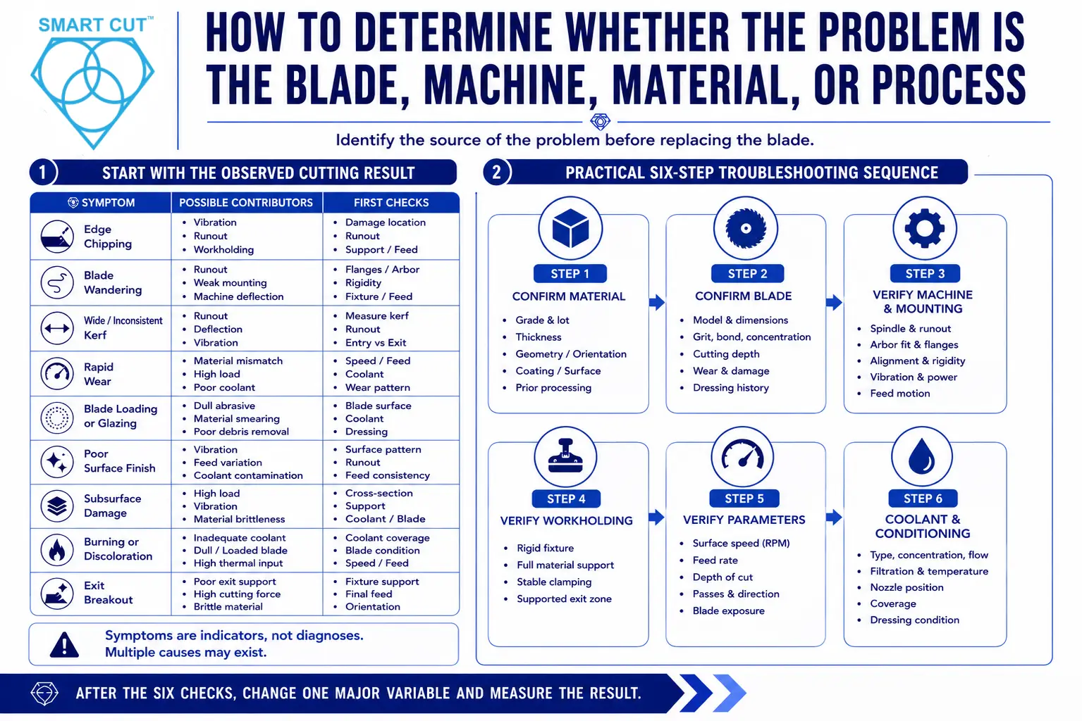
When cutting performance changes, replacing the blade should not automatically be the first response. The more reliable approach is to identify what changed and determine whether the problem follows the blade, remains with the machine, occurs only with one material, or appears only under one set of operating conditions.
Start With the Observed Cutting Result
Define the problem before changing anything. Avoid general descriptions such as “the blade does not work.” Record the measurable symptom and where it occurs.
| Cutting Problem | Possible Contributors | First Checks |
|---|---|---|
| Excessive edge chipping | Cutting load, vibration, runout, workholding, blade compatibility, material fracture | Damage location, installed-blade runout, support, feed, blade condition |
| Blade wandering | Runout, blade exposure, weak mounting, machine deflection, workpiece movement, excessive force | Flanges, arbor, blade seating, rigidity, fixture, feed motion |
| Wide or inconsistent kerf | Runout, deflection, lateral wear, mounting error, vibration, unstable feed | Measure runout and kerf, inspect mounting, compare entry and exit |
| Rapid blade wear | Blade and material mismatch, high load, poor coolant, vibration, unsuitable conditioning | Material, surface speed, feed, coolant, blade wear pattern |
| Blade loading or glazing | Dull abrasive, unsuitable bond behavior, material smearing, poor debris removal | Blade surface, coolant delivery, dressing history, material response |
| Poor surface finish | Grit and bond, vibration, feed variation, coolant contamination, material structure | Surface pattern, filtration, runout, blade condition, feed consistency |
| Subsurface damage | Mechanical load, vibration, material brittleness, thermal stress | Cross-sectional inspection, support, feed, coolant, blade specification |
| Burning or discoloration | Inadequate coolant, dull or loaded blade, high thermal input | Coolant coverage, blade condition, spindle load, surface speed, feed |
| Exit breakout | Inadequate exit support, high cutting force, brittle material, cutting direction | Fixture support, final feed stage, blade condition, material orientation |
These symptoms are indicators, not automatic diagnoses. The same symptom can have several causes, and several causes can be present at the same time.
A Practical Six-Step Troubleshooting Sequence
Step 1: Confirm the material
Verify that the material is comparable with the previous successful test. Check the exact grade, lot, thickness, geometry, orientation, coating, surface condition, and prior processing.
Step 2: Confirm the blade
Document the model, diameter, thickness, arbor, abrasive type, grit, bond, concentration, cutting depth, blade condition, number of previous cuts, and dressing history.
Inspect the blade for visible damage, loading, uneven wear, side contact, or a distorted core.
Step 3: Verify the machine and mounting
Check spindle condition, runout, arbor fit, flange flatness and cleanliness, blade seating, machine rigidity, vibration, alignment, power under load, and feed-system motion.
Measure the installed condition rather than assuming that a clean-looking spindle is accurate.
Step 4: Verify workholding
Confirm that the fixture is rigid, the material is supported, the workpiece does not move, clamping does not introduce stress, and the exit region remains supported.
Step 5: Verify cutting parameters
Record surface speed, RPM, feed rate, actual cutting time, depth of cut, number of passes, cutting direction, blade exposure, and spindle behavior under load.
Step 6: Verify coolant and conditioning
Check coolant type, concentration, flow, filtration, temperature, nozzle position, cutting-interface coverage, and blade dressing condition.
After the six checks, change one major variable and measure the result.
Troubleshooting Excessive Edge Chipping
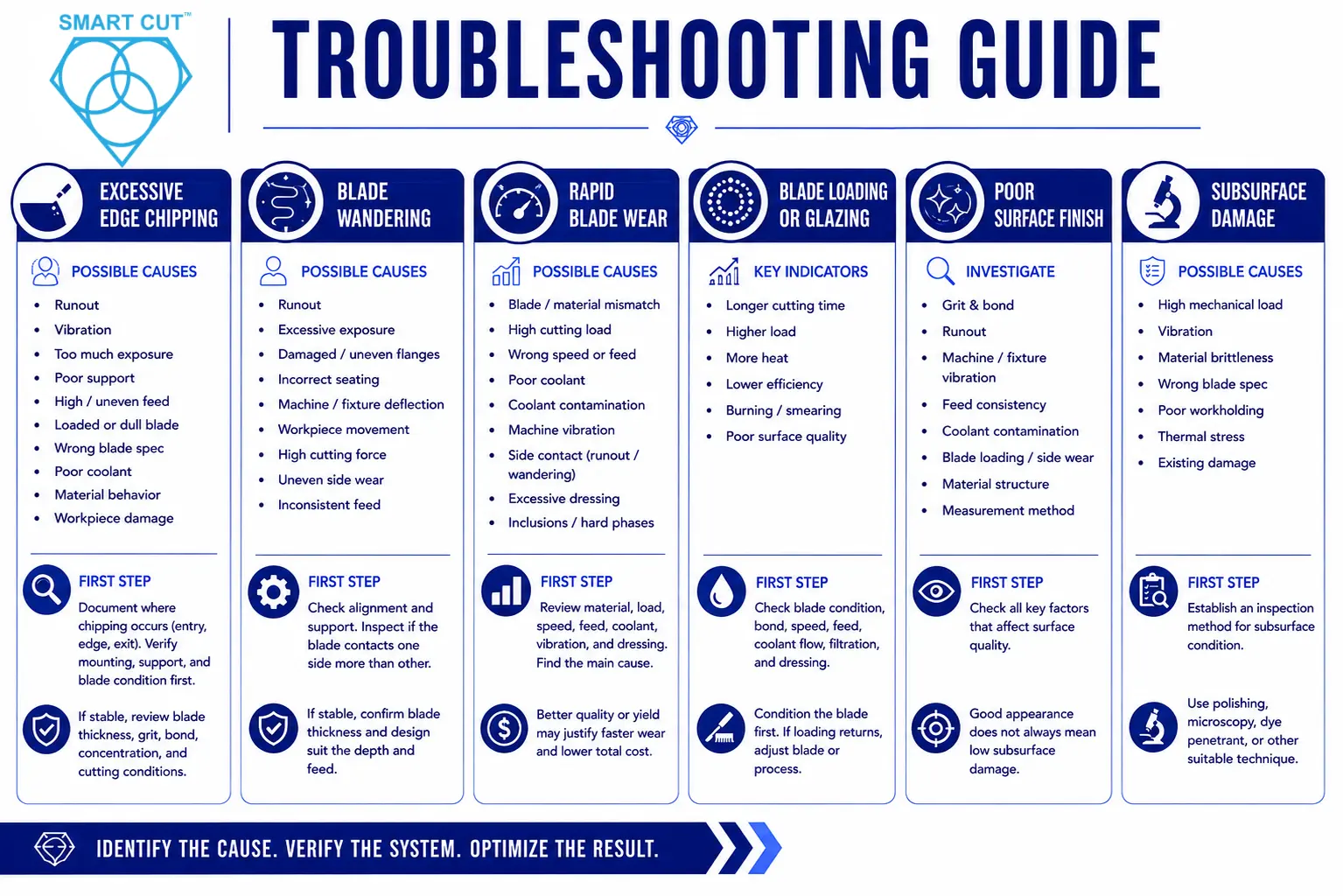
Excessive chipping is common when cutting brittle materials, but it should not be treated as proof that the blade grit is too coarse.
Possible contributors include:
- Excessive installed-blade runout
- Machine vibration
- Too much unsupported blade exposure
- Inadequate workpiece support
- Excessive or inconsistent feed
- A loaded or poorly conditioned blade
- Unsuitable blade specification
- Poor coolant delivery
- Material fracture behavior
- Damage already present in the workpiece
Begin by documenting where the chipping occurs. Compare entry, continuous edge, and exit damage. Verify mounting, support, and blade condition before selecting a different blade.
If the machine and process are stable, then evaluate blade thickness, grit size, bond behavior, concentration, and cutting conditions for the material and required edge quality.
Troubleshooting Blade Wandering
Blade wandering occurs when the blade does not maintain the intended cutting path.
Possible contributors include:
- Spindle or installed-blade runout
- Excessive blade exposure
- Small, damaged, or uneven flanges
- Incorrect blade seating
- Machine or fixture deflection
- Workpiece movement
- Excessive cutting force
- Uneven side wear
- Inconsistent feed motion
Start with mechanical alignment and support. Inspect whether the blade is contacting one side of the cut more heavily than the other. If the mechanical system is stable, evaluate whether the blade thickness and construction provide enough lateral stability for the required depth and feed.
Troubleshooting Rapid Blade Wear
Rapid wear does not necessarily mean that the blade is defective. Wear must be evaluated in the context of the material, cut depth, feed, coolant, machine stability, dressing practice, and quality obtained.
Possible causes include:
- Blade and material incompatibility
- Excessive cutting load
- Unsuitable surface speed or feed
- Poor coolant delivery
- Abrasive contamination in recirculated coolant
- Machine vibration
- Side contact caused by wandering or runout
- Excessive dressing
- Workpiece inclusions or abrasive phases
A blade that wears faster but substantially improves edge quality, yield, or downstream processing may still provide better total process economics than a longer-life blade that creates more damage.
Troubleshooting Blade Loading or Glazing
Blade loading occurs when workpiece material or debris accumulates at the cutting surface. Glazing describes a condition in which the abrasive system becomes dull or ineffective and cutting resistance increases.
Potential indicators include:
- Increasing cutting time
- Higher spindle load
- More heat
- Reduced cutting efficiency
- Material burning or smearing
- Deteriorating surface quality
Investigate the blade condition, bond behavior, material response, surface speed, feed, coolant flow, filtration, and dressing requirements.
Before changing the blade specification, determine whether proper conditioning restores cutting efficiency. If loading returns quickly under controlled conditions, the blade and process may need to be adjusted for the material.
Troubleshooting Poor Surface Finish
Poor surface finish can originate from the blade, machine, material, coolant, or inspection method.
Investigate:
- Diamond grit and bond characteristics
- Installed-blade runout
- Machine and fixture vibration
- Feed consistency
- Coolant contamination
- Blade loading or side wear
- Material porosity, grain pullout, or inclusions
- Surface measurement direction and method
A visually smooth surface does not automatically indicate low subsurface damage. For demanding applications, surface appearance should be evaluated together with edge integrity, dimensional accuracy, and cross-sectional condition.
Troubleshooting Subsurface Damage
Subsurface damage may not be visible at the cut edge. It is especially important when the specimen will undergo microscopy, polishing, semiconductor inspection, bonding, coating, or high-reliability service.
Possible contributors include:
- Excessive mechanical load
- Machine vibration
- Material brittleness
- Unsuitable blade specification
- Poor workholding
- Thermal stress
- Previous material damage
When subsurface condition is critical, establish an inspection method. This may include polishing and microscopy, dye penetrant where applicable, dimensional inspection, or another validated technique appropriate for the material.
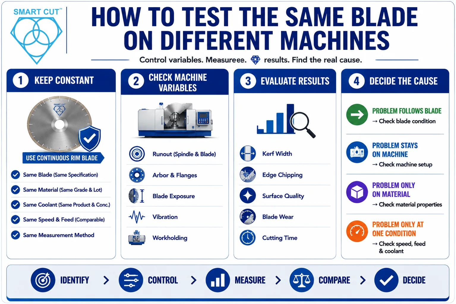
How to Test the Same Blade on Different Machines
To determine whether machine condition is responsible for different results, hold the blade and material conditions as constant as practical.
Use:
- The same blade specification
- Comparable blade condition
- The same material grade and lot
- The same thickness and orientation
- The same workpiece geometry
- The same coolant product and concentration
- Comparable surface speed and feed conditions
- The same dressing condition
- The same measurement method
Then document the machine-specific variables:
- Spindle and installed-blade runout
- Arbor and flange configuration
- Blade exposure
- Spindle power and actual speed under load
- Feed-system type and motion quality
- Workholding
- Coolant delivery and filtration
- Vibration
Evaluate measurable results such as kerf, edge chipping, dimensional accuracy, surface condition, cutting time, spindle load, and blade wear.
How to Test the Same Blade on Different Materials
When comparing materials, keep the machine and blade conditions stable.
Record:
- Material and grade
- Lot or source
- Thickness and geometry
- Hardness or available mechanical data
- Orientation
- Coating or layer structure
- Surface condition
- Prior processing
Interpret the results in the context of the application. A higher level of chipping on a more brittle material does not automatically demonstrate poor blade quality. The correct question is whether the blade produces acceptable performance for that specific material and required result.
Do Not Judge a Blade by One Measurement
A common mistake is selecting the preferred blade using only one result.
- The narrowest kerf does not automatically mean the lowest total cost.
- The longest blade life does not automatically mean the best cut quality.
- The fastest cut does not automatically mean the highest usable output.
- The lowest surface roughness does not automatically mean the lowest subsurface damage.
- The lowest blade price does not automatically mean the lowest cost per acceptable part.
A complete evaluation should consider the measurements that matter to the application.
These may include:
- Edge integrity
- Kerf consistency
- Dimensional accuracy
- Surface condition
- Subsurface damage
- Flatness and parallelism
- Material utilization
- Blade life
- Cutting time
- Operator involvement
- Dressing frequency
- Downstream grinding or polishing
- Yield of acceptable parts
Establish Application-Specific Acceptance Criteria
There is no universal acceptance value for chipping, kerf variation, surface roughness, flatness, or subsurface damage across all diamond blade applications.
Acceptance criteria should come from:
- Component drawings
- Customer specifications
- Validated internal standards
- Downstream process requirements
- Functional performance
- Microscopy or inspection requirements
- Production-yield objectives
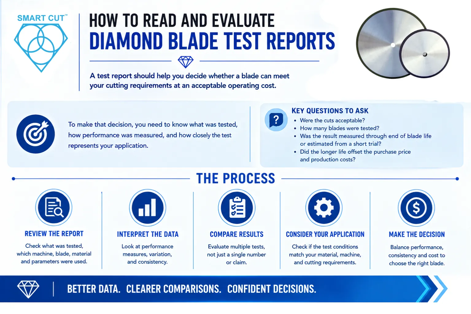
Define acceptance criteria before testing whenever possible. If the criteria change after the results are reviewed, the comparison can become subjective.
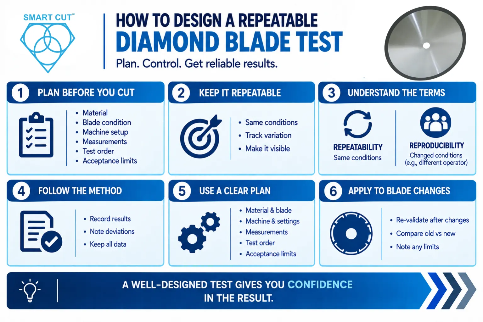
Create a Controlled Blade Qualification Procedure
A repeatable qualification procedure should document the complete cutting system.
| Qualification Area | Information to Record |
|---|---|
| Blade | Model, dimensions, abrasive, grit, bond, concentration, condition, dressing history |
| Machine | Make, model, spindle, arbor, flanges, runout, rigidity, power, feed system |
| Material | Grade, lot, thickness, geometry, orientation, coating, prior processing |
| Workholding | Fixture, support, clamping method, alignment, exit support |
| Process | Surface speed, RPM, feed, cutting time, depth, passes, direction, blade exposure |
| Coolant | Product, concentration, flow, filtration, temperature, nozzle position |
| Results | Kerf, chipping, dimensional accuracy, finish, subsurface damage, wear, cycle time |
| Decision | Acceptance criteria, conclusion, approved range, remaining risks |
Run enough cuts to determine whether the result is repeatable. A single successful cut may not represent production performance. The appropriate sample size depends on material variation, part value, process risk, and production requirements.
When Should the Blade Be Changed?
The following logic helps separate blade problems from machine, material, and process problems.
If the problem follows the blade across multiple machines
Investigate blade condition, blade damage, mounting compatibility, manufacturing variation, or blade specification.
If the problem remains on one machine with different blades
Investigate spindle condition, arbor and flanges, workholding, feed motion, coolant delivery, vibration, and alignment.
If the problem occurs only with one material or material lot
Investigate material characteristics, prior processing, orientation, coating, geometry, and blade-to-material compatibility.
If the problem appears only under one set of cutting conditions
Investigate surface speed, feed, cut depth, blade exposure, coolant, dressing condition, and spindle load.
If the blade no longer responds to proper conditioning
Inspect for wear, damage, loss of abrasive exposure, side wear, core distortion, or a condition that requires replacement.
The blade should be changed when the evidence indicates that its condition or specification is responsible, not simply because a cutting problem appeared.
Practical Engineering Checklist
Before concluding that a precision diamond blade is failing, verify:
- The material grade, thickness, orientation, and lot are correct.
- The blade specification matches the order and application.
- Blade condition and dressing history are known.
- The blade core is not damaged or distorted.
- The arbor and flanges are clean, flat, and appropriate.
- Blade seating and rotation direction are correct.
- Installed-blade runout has been measured.
- Machine rigidity and vibration have been investigated.
- Spindle speed remains stable under load.
- Workholding is rigid and does not stress the part.
- Surface speed and RPM are documented.
- Feed rate and actual cutting time are documented.
- Cutting depth, number of passes, and blade exposure are appropriate.
- Coolant type and concentration are correct.
- Coolant reaches the cutting interface.
- Coolant filtration and tank condition have been checked.
- Edge quality and kerf have been measured.
- Surface and subsurface requirements are defined.
- Results have been compared under controlled conditions.
- Only one major variable was changed during each test.
How UKAM Application Engineering Supports Blade Selection
For demanding applications, selecting a diamond blade often requires more than matching a catalog description to a material name.
UKAM Industrial Superhard Tools manufactures SMART CUT® precision diamond blades and precision cutting machines for applications where controlled sectioning, material preservation, dimensional accuracy, and repeatable performance are important.
The appropriate blade and process depend on the actual material, machine configuration, workpiece geometry, required cut quality, coolant system, production rate, and downstream operation.
For difficult-to-cut, high-value, or damage-sensitive materials, application-specific evaluation can help establish:
- A suitable blade specification
- An appropriate starting surface-speed range
- A practical feed strategy
- Workholding and blade-support requirements
- Coolant and filtration requirements
- Dressing and conditioning procedures
- Inspection and acceptance criteria
Information to Provide When Requesting a Recommendation
To receive a useful recommendation, provide as much of the following information as possible:
- Exact material, grade, hardness, or available technical data
- Workpiece dimensions and required cut depth
- Coatings, layers, reinforcement, or internal structures
- Machine make, model, spindle-speed range, and available power
- Arbor size and flange configuration
- Current blade specification, RPM, feed rate, and actual cutting time
- Coolant type, concentration, flow, and filtration
- Workholding method
- Current cutting problem
- Required kerf, tolerance, edge quality, and surface condition
- Acceptable subsurface damage, if controlled
- Production quantity and required throughput
- Photographs of the blade, mounting arrangement, workholding, and cut result
You can submit this information through UKAM’s application consultation request so the recommendation can be based on the complete cutting system.
Final Engineering Principle
The same diamond blade can produce different results because a diamond blade is only one component of a precision cutting system.
Machine rigidity, spindle accuracy, arbor and flange condition, blade mounting, workholding, material properties, surface speed, feed control, coolant delivery, blade condition, and application requirements all influence the final result.
The most reliable troubleshooting method is to identify what changed, control the remaining variables, measure the cutting response, and determine whether the problem follows the blade, machine, material, or process.
The objective is not simply to find a blade that cuts. The objective is to establish a repeatable process that delivers the required edge quality, dimensional accuracy, kerf, material yield, blade life, productivity, and downstream performance for the specific application.
When a blade is expected to perform across different machines, materials, or workpiece geometries, controlled application testing provides the most reliable basis for qualification and process transfer.
Trusted by Tens of Thousands of Manufacturers, Laboratories,
Research Institutions Worldwide Since 1990
American Based Manufacturer
Established in 1990
Custom manufacturing
RELATED ARTICLES