


Coolant Delivery Optimization for Diamond Core Drilling in Advanced Ceramics
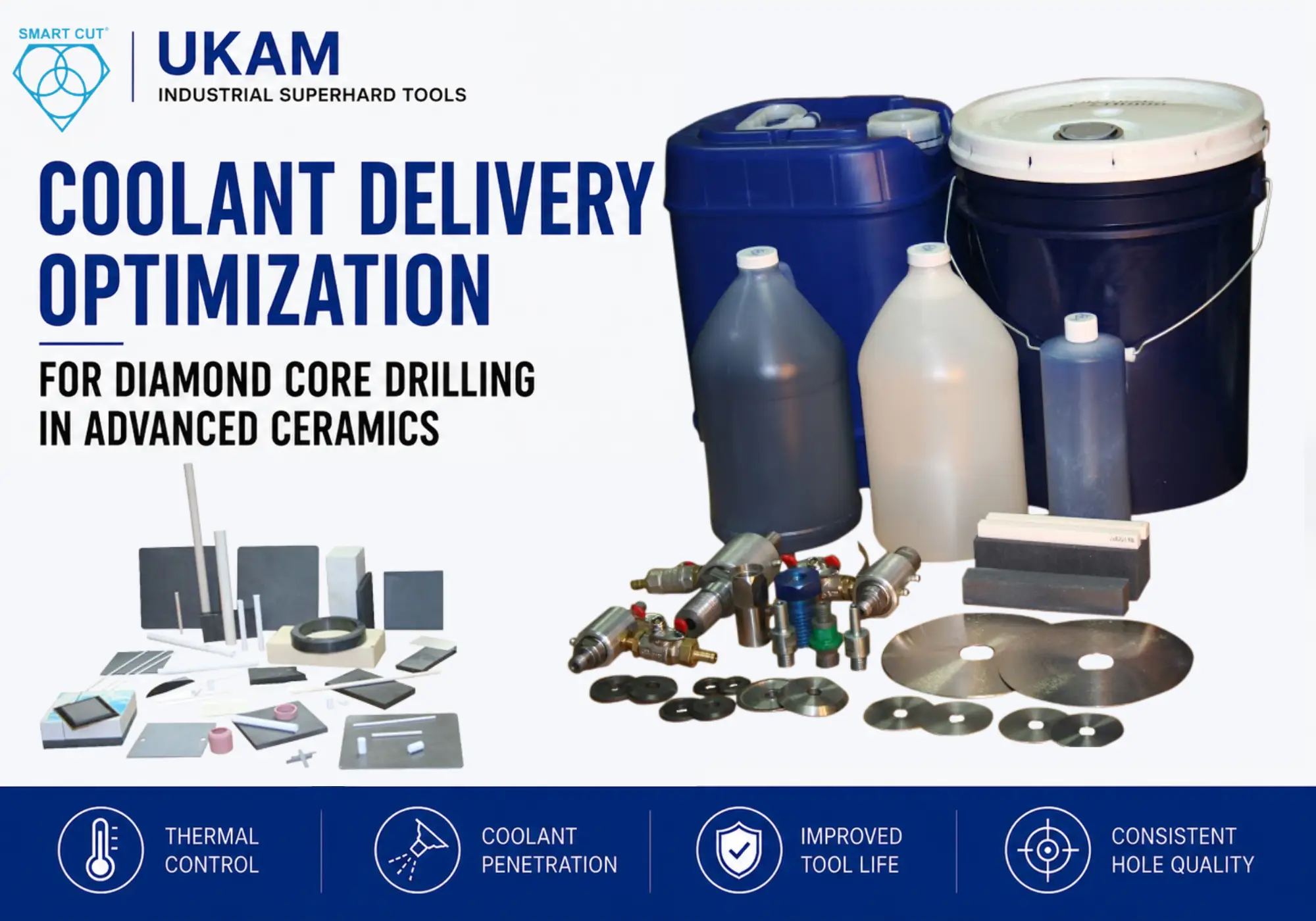
Table of Contents
Toggle
American Based Manufacturer

Established in 1990


Custom manufacturing


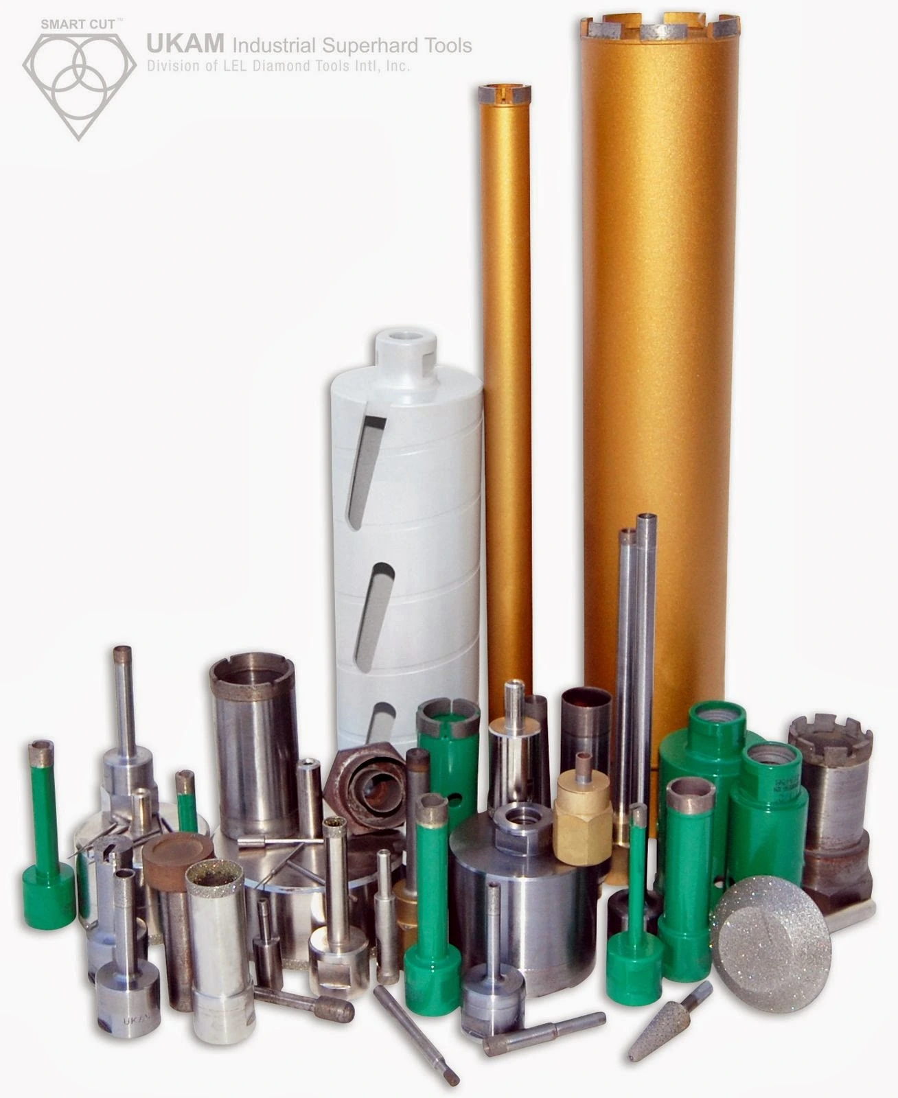
Diamond core drills were failing prematurely during deep-hole drilling of silicon carbide, alumina, sapphire, and fused silica components used in semiconductor, aerospace, and medical manufacturing applications. Operators reported excessive heat generation, rapid diamond loss, edge cracking near hole exits, inconsistent cycle times, and unstable hole tolerances during production drilling.
The original process used standard external flood coolant with general-purpose sintered diamond core drills. The setup produced acceptable results on shallow holes in lower-density ceramics but became unstable during deep-hole drilling above 12 mm depth. Heat accumulated at the cutting interface faster than coolant could evacuate debris and thermal energy. Diamond exposure deteriorated rapidly, spindle load increased progressively, and thermal fracture propagated into the ceramic body.
Initial troubleshooting focused on lowering RPM and reducing feed pressure. These adjustments reduced heat slightly but did not stabilize tool life because coolant penetration at the drilling interface remained inconsistent. The root cause was insufficient coolant delivery into the active cutting zone combined with incorrect bond behavior for highly abrasive ceramic materials.
A revised qualification program evaluated coolant pressure, nozzle geometry, center-feed delivery systems, bond structure, peck cycle frequency, and spindle load trends. Recommended process optimization strategies may include center-feed coolant delivery, controlled peck drilling intervals, and bond structures suited to abrasive ceramic materials. The optimized process improved drilling consistency, coolant penetration, and thermal control during deep-hole ceramic drilling applications. Explore UKAM’s Diamond Core Drills for Ceramics engineered for these applications.
Customer Application and Manufacturing Environment
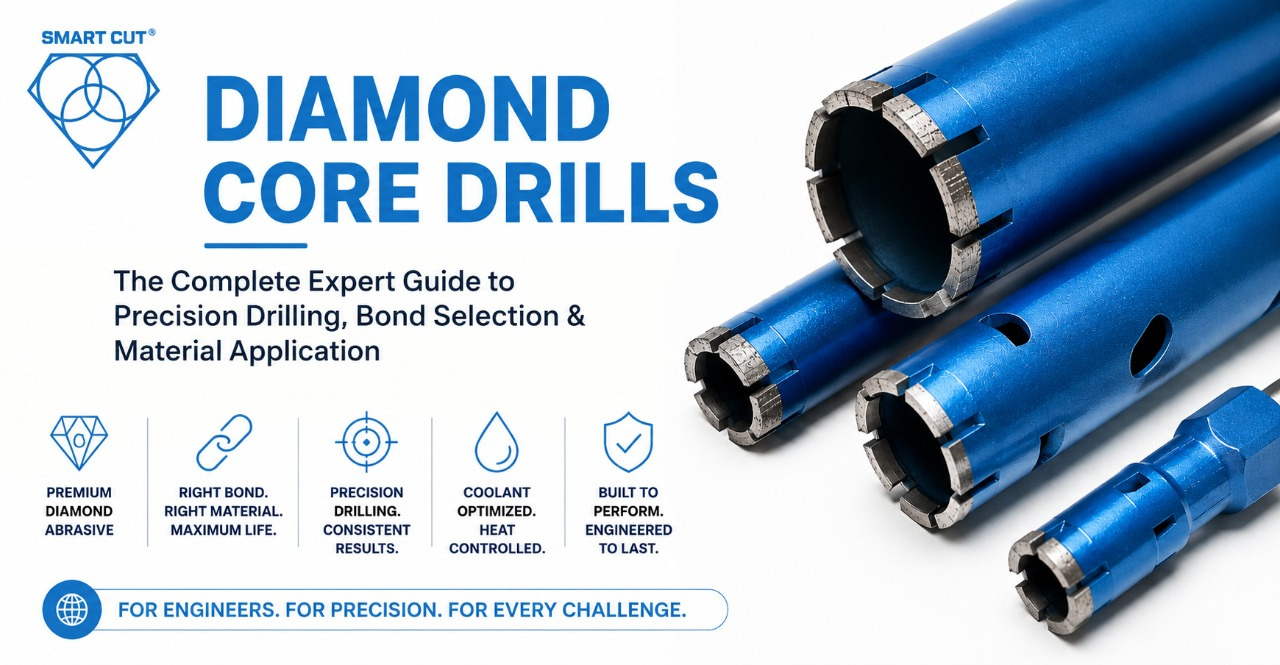
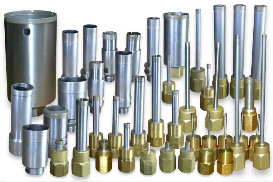
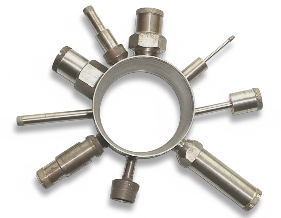
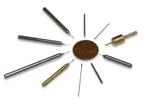
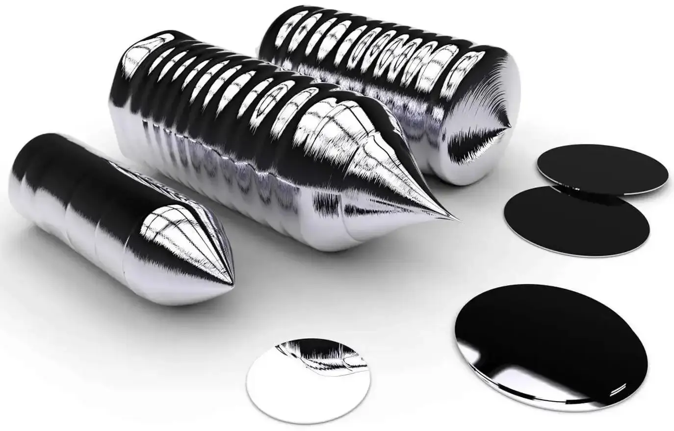
The components were precision ceramic substrates and insulating assemblies used in semiconductor packaging, vacuum systems, and high-temperature electronic applications. Hole geometry ranged from 0.8 mm micro holes to 25 mm through-holes in brittle advanced ceramics. UKAM’s Precision Ceramic Drilling Tools cover this full range of geometries.
Production Environment
|
Parameter |
Original Production Setup |
|---|---|
|
Materials processed |
Silicon carbide, alumina, sapphire, fused silica |
|
Industry |
Semiconductor, aerospace, medical |
|
Machine type |
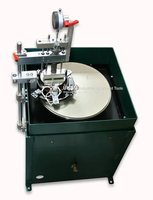
CNC core drilling machine |
|
Drill type |
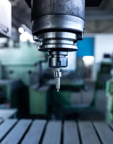
Sintered diamond core dril |
|
Coolant delivery |
External flood coolant |
|
Hole depth range |
4 mm to 25 mm |
|
Hole tolerance |
±0.03 mm |
|
Main production issue |
Thermal damage and rapid drill wear |
|
Typical spindle load instability |
High |
The process became unstable during longer drilling cycles because coolant flow could not consistently reach the cutting interface inside deeper holes
Why Coolant Delivery Fails During Deep Ceramic Drilling

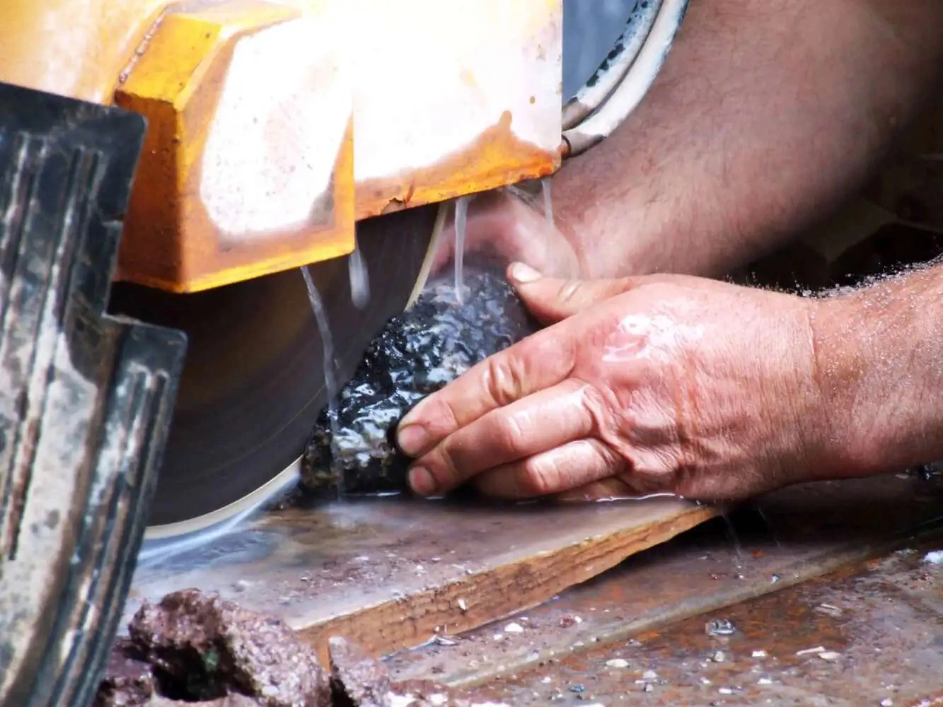
External flood coolant systems often appear adequate during shallow drilling operations because heat escapes more easily from the cutting zone. Deep-hole drilling behaves differently. Coolant flow becomes restricted as hole depth increases, swarf evacuation slows, and thermal energy accumulates inside the drilling interface.
Silicon carbide and alumina amplify this problem because both materials generate abrasive debris that accelerates bond wear while simultaneously increasing friction at the cutting face. See UKAM’s Silicon Carbide Machining Solutions for material-specific guidance
Material Behavior During Drilling
|
Material |
Relative Abrasiveness |
Thermal Sensitivity |
Primary Failure Mode |
|---|---|---|---|
|
Silicon Carbide |
Very high |
Moderate |
Rapid drill wear |
|
Alumina 99.6% |
Moderate |
High |
Edge breakout |
|
Sapphire |
Low |
Very high |
Thermal cracking |
|
Fused Silica |
Low |
Very high |
Micro fracture propagation |
|
Silicon Nitride |
Moderate |
High |
Corner chipping |
|
Quartz |
Moderate |
High |
Heat cracking |
The original drilling setup relied entirely on external coolant flooding. Once hole depth exceeded approximately 2× drill diameter, coolant penetration into the active cutting zone became inconsistent.
Baseline Documentation Before Process Optimization
The engineering team documented production conditions before modifying drilling parameters. Several previous troubleshooting attempts failed because operators changed multiple variables simultaneously.
Baseline Qualification Data
|
Parameter |
Measurement Method |
Unit |
Notes |
|---|---|---|---|
|
Material grade |
Incoming inspection |
Material type |
Verify purity and density |
|
Drill specification |
Supplier documentation |
Bond and grit |
Confirm concentration |
|
Drill diameter |
Caliper verification |
mm |
Verify actual OD |
|
Spindle speed |
Tachometer |
RPM |
Verify loaded RPM |
|
Surface speed |
Calculated |
SFM |
Primary drilling parameter |
|
Feed rate |
CNC verification |
mm/min |
Record actual feed |
|
Coolant pressure |
Inline gauge |
PSI |
Verify during drilling |
|
Coolant flow rate |
Flow meter |
GPM |
Measure at nozzle |
|
Peck interval |
CNC cycle verification |
mm |
Track retract frequency |
|
Hole cycle time |
Machine monitoring |
Seconds |
Compare by depth |
|
Spindle load |
Machine monitoring |
% load |
Monitor continuously |
|
Scrap rate |
Inspection report |
% rejected parts |
Primary KPI |
The process review identified two repeating trends. Spindle load increased sharply during holes deeper than 10 mm, and coolant pressure fluctuated significantly during extended drilling cycles.
Coolant Delivery Variables to Document During Qualification
|
Variable |
Why It Matters |
|---|---|
|
Coolant Method |
Determines heat removal capability |
|
Nozzle Position |
Influences interface cooling |
|
Coolant Pressure |
Affects penetration into deep holes |
|
Coolant Flow Rate |
Affects debris evacuation |
|
Filtration Quality |
Influences tool wear consistency |
|
Drill Design |
Influences coolant access |
Existing Process Problems
The original drilling process generated stable results during low-volume prototyping but failed during continuous production runs.
Production Failure Indicators
|
Observation |
Root Cause |
|---|---|
|
Burned swarf |
Excess heat accumulation |
|
Dark coolant discharge |
Bond degradation |
|
Rapid diamond pullout |
Insufficient cooling |
|
Increasing cycle times |
Drill loading |
|
Hole taper variation |
Uneven drill wear |
|
Edge cracking near exits |
Thermal stress |
|
Frequent dressing requirements |
Poor self-sharpening |
Operators attempted to compensate by lowering feed pressure, which reduced throughput but did not stabilize drill wear
Quick Troubleshooting Guide for Diamond Core Drilling
|
Symptom |
Likely Cause |
|---|---|
|
Edge chipping near hole exit |
Excessive feed pressure or thermal stress |
|
Dark coolant discharge |
Bond degradation or excessive wheel wear |
|
Rising spindle load |
Poor coolant penetration or drill loading |
|
Hole taper variation |
Uneven tool wear or machine instability |
|
Thermal cracks |
Excessive heat accumulation |
|
Rapid diamond pullout |
Inadequate coolant delivery |
|
Increasing cycle times |
Drill loading and reduced cutting efficiency |
|
Frequent dressing requirements |
Improper bond selection |
Engineering Note: These symptoms should be evaluated together with coolant delivery, drill specification, bond structure, machine rigidity, and process parameters. Changing a single variable rarely resolves deep-hole ceramic drilling problems permanently.
Cost Per Part Analysis: Conventional Coolant Setup vs Optimized Coolant Delivery
Drill price alone does not determine production economics. Tool life, coolant efficiency, spindle stability, scrap rate, and production downtime strongly affect actual manufacturing cost.
|
Cost Factor |
Impact on Production Cost |
|---|---|
|
Tool Life |
Influences replacement frequency |
|
Scrap Rate |
Affects material waste and yield |
|
Cycle Time |
Influences throughput |
|
Dressing Frequency |
Creates machine downtime |
|
Coolant Efficiency |
Influences thermal stability |
|
Process Stability |
Impacts consistency and quality |
In many advanced ceramic drilling applications, thermal stability is often one of the most influential factors affecting tool life, hole quality, and process consistency.
Coolant Qualification Trials
The engineering group evaluated multiple coolant delivery configurations during qualification testing.
Qualification Matrix
|
Setup |
Coolant Method |
Relative Tool Life |
Relative Scrap Rate |
Process Stability |
|---|---|---|---|---|
|
A |
External Flood Coolant |
Baseline |
Highest |
Poor |
|
B |
Directed Nozzle Flow |
Improved |
Reduced |
Moderate |
|
C |
Center-Feed Coolant |
Significantly Improved |
Lower |
Stable |
|
D |
Center-Feed + Adaptive Peck Cycle |
Highest |
Lowest |
Most Stable |
Add note: Actual tool life, coolant pressure, flow rate, and scrap rate values vary depending on material, drill geometry, machine rigidity, and hole depth. Application-specific qualification testing is recommended.
Explore UKAM’s Center-Feed Diamond Core Drills designed for deep-hole ceramic applications.
Why RPM Reduction Alone Failed
The production team initially attempted to solve thermal cracking by reducing spindle RPM while maintaining the original coolant configuration. The approach lowered heat generation slightly but did not stabilize drilling conditions because coolant penetration remained inconsistent. Abrasive debris continued accumulating inside deeper holes, increasing friction and thermal loading.
Root Cause Evaluation
|
Attempted Correction |
Result |
Why It Failed |
|---|---|---|
|
Lower spindle RPM |
Minor improvement |
Coolant penetration unchanged |
|
Reduced feed pressure |
Better edge quality |
Throughput unacceptable |
|
Increased flood coolant volume |
Moderate improvement |
Interface cooling still inconsistent |
|
More frequent peck cycles |
Improved debris removal |
Heat accumulation remained |
|
Center-feed coolant system |
Major improvement |
Direct cooling at drilling interface |
The qualification trials confirmed that coolant delivery geometry affected drill life more significantly than RPM reduction alone.
Technical Explanation: Why Center-Feed Coolant Worked
Center-feed coolant delivery directs coolant through the drill body directly into the cutting interface. This stabilizes temperature, improves debris evacuation, and reduces localized friction at the drilling face.
The original external coolant system cooled the outside surface effectively but failed to remove heat from the internal drilling interface during deeper cuts.
Coolant System Comparison
|
Parameter |
External Flood Coolant |
Center-Feed Coolant |
|---|---|---|
|
Interface cooling |
Limited |
Direct |
|
Debris evacuation |
Moderate |
Improved |
|
Thermal stability |
Variable |
Stable |
|
Drill wear consistency |
Unstable |
Improved |
|
Diamond retention |
Lower |
Higher |
|
Hole quality consistency |
Variable |
More repeatable |
Thermal management improved because coolant reached the highest heat concentration area directly rather than relying on indirect surface cooling
Peck Cycle Optimization
Continuous drilling generated unstable heat accumulation during holes deeper than 12 mm. The revised process introduced controlled retract intervals to evacuate debris and restore coolant access.
|
Drilling Method |
Thermal Stability |
Tool Life |
|---|---|---|
|
Continuous drilling |
Variable |
Lower |
|
Fixed peck intervals |
Improved |
Moderate |
|
Adaptive peck cycle |
Stable |
Highest |
Supplier Evaluation
|
Question |
What the Answer Reveals |
|---|---|
|
What coolant pressure is recommended for deep-hole ceramic drilling? |
Process engineering capability |
|
Does the drill support center-feed coolant delivery? |
Deep-hole application knowledge |
|
What bond structure is recommended for silicon carbide? |
Abrasive behavior understanding |
|
What peck interval is recommended for deep holes? |
Real production experience |
|
What spindle parameters were used during qualification? |
Process validation capability |
|
Can different bond systems be recommended for shallow and deep holes? |
Advanced drilling expertise |
Suppliers focused only on drill dimensions and pricing rarely provide stable process optimization support for advanced ceramic drilling operations.
SMART CUT Process Comparison
|
Parameter |
Conventional Flood Coolant Process |
SMART CUT Optimized Drilling Process |
|---|---|---|
|
Thermal loading |
Higher |
Reduced |
|
Coolant penetration |
Limited |
Improved |
|
Drill wear consistency |
Variable |
Stable |
|
Diamond retention |
Lower |
Improved |
|
Spindle load stability |
Unstable |
More consistent |
|
Hole quality consistency |
Variable |
More repeatable |
|
Scrap rate |
Higher |
Reduced |
In many advanced ceramic drilling applications, direct interface cooling can provide greater process stability than RPM reduction alone. For precision cutting applications, explore UKAM’s Diamond Dicing Blades and Precision Grinding Wheels.
Coolant Delivery Method Comparison
|
Method |
Typical Advantage |
Typical Limitation |
|---|---|---|
|
External Flood |
Simple setup |
Less effective at depth |
|
Directed Nozzle |
Improved targeting |
Limited penetration |
|
Center-Feed |
Direct interface cooling |
Requires compatible tooling |
|
Center-Feed + Adaptive Peck |
Improved cooling and debris evacuation |
Higher process complexity |
Qualification Checklist
Machine Condition
- Verify spindle runout below 0.0003 inches
- Confirm machine rigidity during deep-hole drilling
- Inspect spindle bearing condition
- Verify spindle speed stability
Coolant System
- Measure coolant pressure at drilling interface
- Verify center-feed flow consistency
- Inspect nozzle alignment
- Check coolant filtration condition
Drill Qualification
- Validate peck cycle consistency
- Record spindle load trends
- Confirm bond specification
- Verify drill balance and concentricity
Process Parameters
- Record feed rates by hole depth
- Monitor thermal discoloration
- Track hole taper variation
- Record scrap rate by shift
Frequently Asked Questions
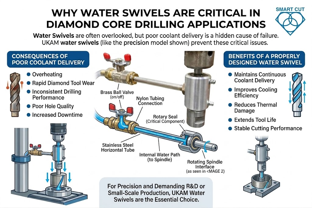
External coolant systems cool exposed surfaces effectively but struggle to reach the active drilling interface inside deeper holes. Heat accumulation increases rapidly once coolant penetration becomes restricted.
Center-feed systems direct coolant into the highest heat concentration area at the cutting interface. This stabilizes temperature, improves debris evacuation, and reduces friction at the drilling face.
Lower spindle speed reduced heat generation slightly but did not correct the underlying coolant penetration problem. Abrasive debris still accumulated inside deeper holes, increasing friction and thermal loading.
Silicon carbide generates aggressive abrasive wear while simultaneously producing high cutting force. Bond structures optimized for alumina or ferrite materials often fail rapidly during SiC drilling operations.
Adaptive retract cycles restored coolant access and evacuated abrasive debris before thermal accumulation became unstable. Fixed peck intervals were less effective because heat generation changed with drilling depth.
Spindle load trends revealed drill instability before visible edge damage or catastrophic failure occurred. Stable spindle load usually indicates stable abrasive exposure and thermal behavior.
In many advanced ceramic drilling applications, coolant penetration and thermal control are among the most influential variables affecting process stability.
Key Engineering Principles
- Deep-hole ceramic drilling failures are primarily thermal management and coolant delivery problems.
- External flood coolant becomes less effective as hole depth increases.
- Center-feed coolant systems stabilize interface temperature and debris evacuation.
- Silicon carbide requires different bond behavior than alumina or ferrite materials.
- Controlled self-sharpening improves drilling stability in abrasive ceramics.
- Adaptive peck cycles reduce thermal accumulation during deep drilling.
- Spindle load monitoring provides early warning of drill instability.
- Stable drilling performance requires balancing coolant delivery, bond behavior, machine rigidity, and feed pressure together.
- Scrap reduction often produces larger savings than maximizing drill retention alone.
- Deep-hole ceramic drilling processes should be qualified separately by material family and hole depth range.
Trusted by Tens of Thousands of Manufacturers, Laboratories,
Research Institutions Worldwide Since 1990
American Based Manufacturer
Established in 1990
Custom manufacturing
RELATED ARTICLES