





















Diamond Wire Saw Troubleshooting: A Root-Cause Guide for Manufacturing Engineers

Table of Contents
Toggle
American Based Manufacturer

Established in 1990


Custom manufacturing


Treat Cutting Defects as Process Failures, Not Just Tool Problems
When a diamond wire sawing process begins producing chipped edges, inconsistent kerf, wire breakage, or longer cutting cycles, replacing the consumable may not resolve the underlying problem.
For manufacturing engineers, the first task is to determine what changed, where the failure occurs, and whether the evidence points to the wire, machine, workpiece, or operating conditions.
A useful investigation separates three things:
- Observed symptom: what the operator or inspection system actually detects.
- Suspected cause: the process condition that might explain the symptom.
- Verified root cause: a cause supported by repeatable measurements or controlled testing.
This distinction matters in precision cutting of silicon, sapphire, quartz glass, ceramics, and other hard materials. A change that reduces one visible defect may increase cycle time, material loss, or another defect elsewhere.
This article focuses on diagnosing production faults, validating corrective actions, and deciding when a process is ready for release. For general information about wire configurations and machine designs, see UKAM’s Guide to Diamond Wire Sawing.
Establish Exactly What Has Changed
Before adjusting feed rate, tension, or wire speed, compare the affected production run with the last known acceptable condition.
Start with the production records rather than relying on operator recollection. Review whether the problem appeared after a wire change, material-lot change, machine maintenance, fixture adjustment, coolant change, or program revision.
|
Data category |
Information to capture |
Question it helps answer |
|---|---|---|
|
Defect |
Type, location, frequency, and measured severity |
Is the failure consistent or variable? |
|
Workpiece |
Material grade, lot, geometry, and orientation where relevant |
Did the material or cutting geometry change? |
|
Wire |
Product designation, specification, lot, and operating history |
Did the consumable configuration change? |
|
Machine |
Equipment identification, maintenance, alarms, and setup |
Did the problem coincide with a machine event? |
|
Operating settings |
Actual and commanded feed, wire speed, and tension where measurable |
Is the process following the approved recipe? |
|
Coolant |
Product, concentration, flow, temperature, and delivery condition |
Has the cutting environment changed? |
|
Quality |
Kerf, dimensional deviation, edge damage, and surface inspection |
Which acceptance requirement is failing? |
|
Production |
Cutting time, total cycle time, downtime, and wire consumption |
What is the operational impact? |
Use consistent inspection methods and measurement units. If edge damage is measured with magnification, retain the same inspection method throughout the investigation.
Where the process lacks a reliable baseline, establish one using an approved condition before attempting optimization. Do not assume that the most recent settings were necessarily the best-qualified settings.
Diagnose Wire Breakage Using Failure Evidence
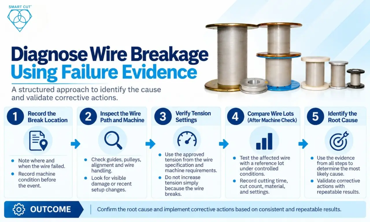
Repeated wire breakage can cause scrap, machine downtime, interrupted production, and additional setup work. The break itself is evidence, but it does not automatically identify the cause.
Step 1: Record the break location
Document where the wire failed and the machine condition immediately before the event. Check whether failures repeatedly occur in the same region, during a particular cutting phase, or after a similar amount of operation.
A repeated location may justify closer inspection of the wire path and associated machine components. It does not, by itself, prove that a guide or pulley caused the failure.
Step 2: Inspect the wire path and machine
Follow the machine manufacturer’s inspection procedure. Check relevant guides, pulleys, alignment, wire handling, and visible damage. Review recent maintenance or setup changes.
Where the machine provides tension or drive monitoring, compare the readings with the approved operating range and available historical records.
Step 3: Verify the tension specification
Do not increase tension simply because the wire breaks.
The wire’s breaking force is not its normal operating-tension setting. Approved working tension must be determined from the applicable wire specification and machine requirements.
UKAM’s diamond wire product information discusses the importance of tension to cutting stability. The appropriate setting remains application-specific. See the UKAM diamond wire product page.
Step 4: Compare wire lots only after checking the machine
If mechanical and setup problems have been investigated, compare the affected wire with a suitable reference lot under controlled conditions.
Record operating time, number of cuts or cutting length where applicable, breakage frequency, material, and operating settings. A single successful run with a replacement wire does not establish that the original wire was defective.
Corrective-action criterion: do not close the investigation until the suspected cause has supporting evidence and the corrective action demonstrates repeatable operation within the approved limits.
Diagnose Chipping and Surface Defects by Location
A general statement such as “the cut quality is poor” is not sufficient for root-cause analysis. Record the defect type, position, frequency, and severity.
|
Defect pattern |
Investigation priority
|
Evidence to collect |
|---|---|---|
|
Damage concentrated at entry |
Entry conditions, workpiece support, and initial feed behavior |
Entry-edge inspection and setup records |
|
Damage concentrated at exit |
Exit conditions, part support, and cut completion |
Exit-edge inspection and workpiece restraint |
|
Damage along one side |
Alignment, workpiece movement, and cutting geometry |
Kerf measurements and fixture checks |
|
Material condition, wire condition, and process stability |
Material traceability, surface inspection, and parameter history |
|
|
Variable damage between nominally identical parts |
Setup repeatability, material variation, and machine condition |
Results grouped by lot, machine, and operator |
These patterns guide the investigation; they are not universal diagnoses. Several causes can produce similar defects.
Verify workpiece support first
Confirm that the part is held securely and that its support remains suitable throughout the cutting cycle. Review the fixture arrangement, clamping procedure, and workpiece condition.
For brittle materials, a defect may become visible during cutting or later processing. Where subsurface damage is critical, visual inspection alone may not establish compliance. Use the inspection method required by the drawing, process specification, or customer acceptance criteria.
Test process parameters systematically
Once the workholding and machine condition have been checked, examine the approved feed rate, wire speed, tension, and coolant conditions.
Do not reduce feed rate automatically. A lower setting may reduce throughput while leaving the real cause untouched. If the suspected cause is uncertain, design a controlled trial rather than making several adjustments at once.
Corrective-action criterion: the selected adjustment must reduce the defined defect without causing unacceptable changes in dimensions, surface condition, cycle time, or other critical quality characteristics.
Investigate Inaccurate Cuts and Variable Kerf
When kerf width, cut straightness, or final dimensions vary, first confirm that the measurement method is repeatable.
Inspect the cut at several defined positions rather than relying on one measurement. Record the location of each measurement so that the results can be compared across workpieces.
Recommended diagnostic sequence
- Verify the measurement system. Check instrument suitability, calibration status where applicable, and measurement repeatability.
- Check workpiece restraint. Confirm that the part remains in its intended position during cutting.
- Inspect the wire path and machine condition. Follow the equipment manufacturer's procedure for alignment and relevant mechanical checks.
- Compare commanded and actual settings. Review the operating record for feed, tension, and wire speed.
- Compare the results by material and setup. Look for patterns linked to particular lots, machines, or fixture arrangements.
- Repeat the measurement after correction. Use the same measurement locations and method.
Do not attribute an inaccurate cut to wire diameter alone without checking the full system. Actual kerf and cut geometry can reflect multiple interacting factors.
If the error remains after basic checks, define the measured deviation and review it with the machine or tooling supplier. Provide the workpiece material, geometry, measured results, current settings, and machine configuration rather than requesting a recommendation based only on the symptom.
Investigate Increasing Cutting Time Without Sacrificing Quality
An increase in cycle time can result from slower cutting, machine interruptions, loading delays, alignment work, or inspection requirements. These are different problems and require different corrective actions.
Separate total cycle time into the activities that make up the process.
|
Time component |
What to record |
|---|---|
|
Wheel shape and profile |
Time from workpiece handling to verified setup |
|
Alignment and approach |
Time required before material engagement |
|
Actual cutting |
Time during which the cutting operation is performed |
|
End-of-cut operations |
Dwell or other programmed completion steps |
|
Unloading and inspection |
Time to remove and assess the part |
|
Interruptions |
Alarms, adjustments, stops, and recovery time |
Compare these components with the last acceptable production run. If actual cutting time increased, investigate material variation, wire condition, feed execution, and machine behavior. If cutting time remains stable but total cycle time rises, investigate handling, setup, inspection, or interruptions.
Avoid increasing feed rate until the cause is understood. A faster programmed feed does not guarantee a faster accepted-part cycle if it increases defects or triggers machine limitations.
Control Coolant and Process Conditions During Troubleshooting
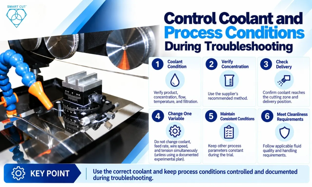
Coolant condition is one of the process variables to record when investigating inconsistent cutting results. Check the specified product, dilution or concentration, flow, temperature, filtration, and delivery position.
For a concentration-controlled coolant, verify the mixture using the method specified by the coolant supplier. Confirm that the fluid reaches the cutting zone and that the delivery system is functioning as intended.
UKAM provides product-specific information for its SMART CUT® diamond wire and related coolant products. Use the current documentation for the exact product and application rather than transferring a dilution ratio or coolant recipe from another process.
During a troubleshooting trial, do not change coolant concentration, feed rate, wire speed, and tension simultaneously. If multiple variables must be investigated together, use a documented experimental plan that allows their individual and combined effects to be evaluated.
For processes with strict contamination requirements, include the applicable fluid quality and handling requirements in the qualification plan.
Run a Controlled Root-Cause Trial
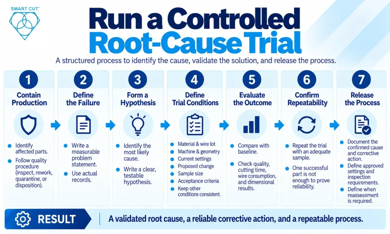
A trial should answer a specific question. It should not be a sequence of undocumented adjustments made until the cut looks acceptable.
Phase 1: Contain affected production
Identify potentially affected parts and follow the applicable quality procedure for inspection, rework, quarantine, or disposition.
Phase 2: Define the failure
Write a measurable problem statement. For example:
Edge chipping exceeded the established acceptance limit on three consecutive production lots after a setup change.
Use actual records to complete the statement. Do not invent a defect rate or claim a trend without evidence.
Phase 3: Form a testable hypothesis
For example:
The setup change may have altered workpiece restraint. Inspecting the fixture and repeating the cut under the previously qualified setup will test this hypothesis.
Phase 4: Define the trial conditions
Record the material lot, wire lot, machine, workpiece geometry, current settings, proposed change, sample size, and acceptance criteria.
Keep other relevant conditions consistent where practical. Where variables interact, use a structured experimental design.
Phase 5: Evaluate the outcome
Compare the trial with the baseline using the same measurement methods. Include quality, cutting time, wire consumption, dimensional results, and any relevant machine events.
Phase 6: Confirm repeatability
Repeat the trial across a sample appropriate to the risk and variability of the application. One successful part does not demonstrate that a corrective action is reliable.
Phase 7: Release the process
Document the confirmed cause, corrective action, approved settings, inspection requirements, and conditions under which the process must be reassessed.
Calculate the Cost of the Failure
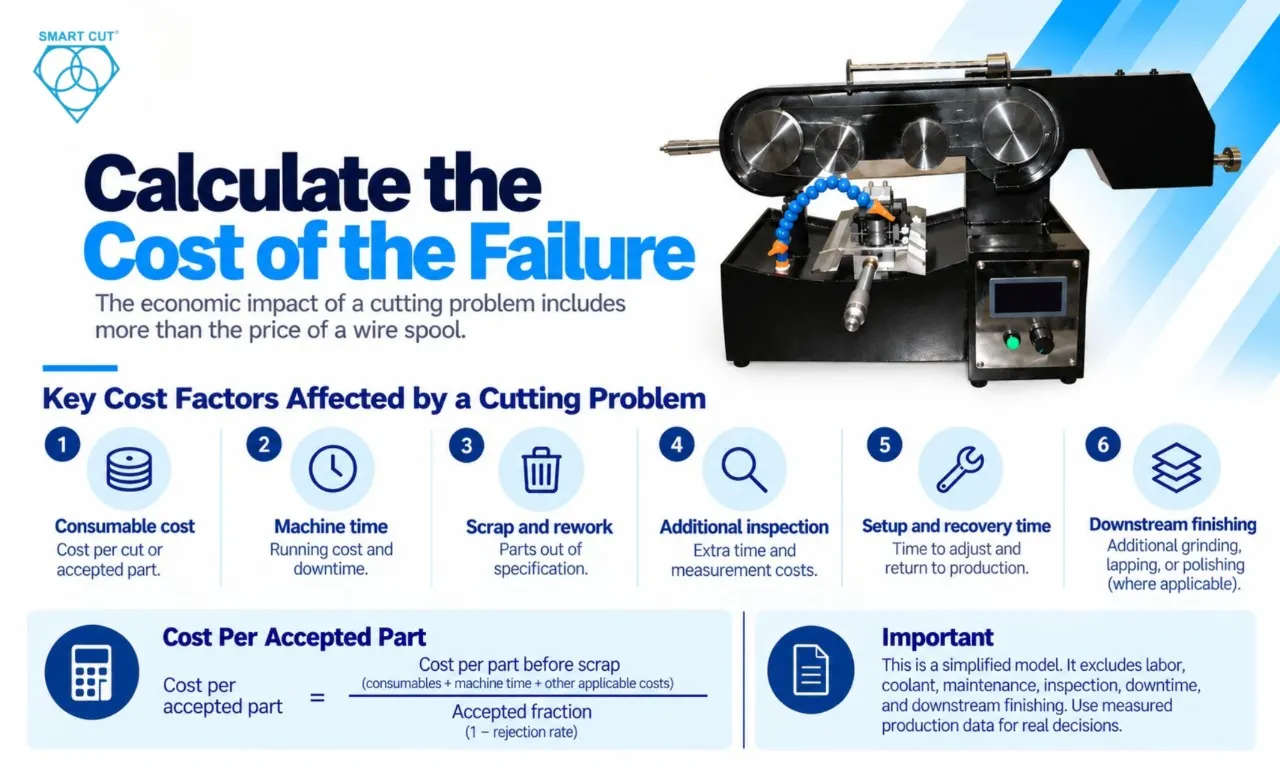
The economic impact of a cutting problem includes more than the price of a wire spool. Engineers should evaluate the costs that are directly affected by the failure.
A useful analysis can include:
- Consumable cost per cut or accepted part
- Machine time and downtime
- Scrap and rework
- Additional inspection
- Setup and recovery time
- Downstream finishing where applicable
Illustrative cost-per-accepted-part calculation
The following example uses hypothetical values only. It is not actual UKAM pricing or verified UKAM performance.
|
Measure |
Scenario A |
Scenario B |
|---|---|---|
|
Wire cost per cut |
$1.00 |
$0.875 |
|
Machine cost per cut |
$12.00 |
$9.00 |
|
Combined cost before scrap |
$13.00 |
$9.875 |
|
Assumed rejection rate |
5% |
2% |
|
Accepted fraction |
95% |
98% |
|
Estimated cost per accepted part |
$13.68 |
$10.08 |
The calculation is:
Cost per accepted part =Cost per part before scrapAccepted fraction
For Scenario A:
$13.000.95≈ $13.68
For Scenario B:
$9.8750.98≈ $10.08
Under these assumptions, Scenario B has the lower estimated cost per accepted part.
This is a simplified model. It excludes labor, coolant, maintenance, inspection, downtime, and downstream finishing. The assumptions must be replaced with measured production data before using the comparison to justify a purchasing or process decision.
The purpose is to demonstrate the calculation method, not to suggest that a particular wire will achieve the assumed cycle time or rejection rate.
When to Escalate to the Machine or Wire Supplier
Escalation is appropriate when the initial investigation does not isolate the cause, when the fault repeats after a controlled correction, or when the machine and wire specifications do not clearly define an acceptable operating condition.
Prepare a technical evidence package before requesting support.
|
Information to provide |
Why it is useful |
|---|---|
|
Establishes equipment context |
|
|
Material grade and workpiece geometry |
Defines the application |
|
Wire product, specification, and lot |
Identifies the consumable |
|
Current operating settings |
Establishes the process condition |
|
Defect measurements and photographs where appropriate |
Documents the failure |
|
Breakage or alarm history |
Establishes the failure pattern |
|
Coolant information |
Records a relevant process variable |
|
Baseline and trial results |
Shows what has already been tested |
|
Required acceptance criteria |
Defines what a successful correction must achieve |
For product-specific questions, engineers can refer to the UKAM Diamond Wire product page. For broader information about wire configurations and machine designs, use the UKAM diamond wire sawing guide.
The troubleshooting article should remain the destination for readers investigating production defects; the other pages provide supporting product and technology information.
Production Release Checklist
Before returning a corrected process to routine production, verify the following:
- The failure has been defined using measurable criteria.
- A baseline has been established or reconstructed from reliable records.
- Material, wire, machine, and coolant conditions have been documented.
- The suspected cause is supported by evidence.
- Relevant mechanical and setup checks have been completed.
- The approved process settings and inspection requirements have been documented.
- Corrective actions have been tested under controlled conditions.
- Quality requirements have been met using the approved inspection method.
- Repeatability has been demonstrated across a suitable sample.
- Cutting time, wire consumption, and rejection rate have been recorded.
- The economic impact has been recalculated using actual data.
- The current wire and machine specifications have been verified.
A process should not be treated as fully qualified while critical acceptance requirements remain unverified.
Frequently Asked Questions
Record the break location and operating conditions, then inspect the wire path, relevant machine components, and tension history. Confirm the approved operating limits before changing settings. Do not assume that the wire is defective based on one breakage event.
Measure the location and severity of the damage. Check workpiece restraint, material condition, machine setup, and the history of operating parameters. Test a specific corrective action and confirm that the improvement is repeatable.
Material variation, machine performance, feed execution, setup delays, and inspection requirements can all affect production time. Compare actual cutting time with total cycle time and review changes against the last qualified baseline.
No. Reducing feed may be appropriate in some cases, but it can also reduce throughput without correcting the cause. First investigate the defect, workpiece support, machine condition, and current operating settings.
Provide the machine configuration, material grade, workpiece dimensions, wire specification and lot, operating settings, defect measurements, coolant condition, and results from previous trials. This gives the supplier a clearer basis for technical guidance.
Define acceptance criteria before the trial, document the operating conditions, compare results with the baseline, and test repeatability across a suitable sample. Release the process only after the applicable quality requirements are satisfied.
Conclusion: Close the Investigation With Evidence
Diamond wire saw troubleshooting should begin with a measurable defect and end with a documented, repeatable corrective action.
The most effective sequence is to establish the baseline, inspect the relevant machine and workpiece conditions, test the suspected cause, measure the result, and confirm repeatability before production release.
For engineers, the key question is not simply which wire or parameter to change. It is which process condition caused the failure, what evidence supports that conclusion, and whether the correction consistently restores the required quality and productivity.
That focus makes troubleshooting more useful than generic advice about cutting speed, wire selection, or product benefits. It also gives manufacturing teams a defensible basis for quality decisions, supplier discussions, and cost-control improvements.
American Based Manufacturer
Established in 1990
