








































Diamond Lapping Disc Selection: How Engineers Choose Grit, Bond, and Disc Type

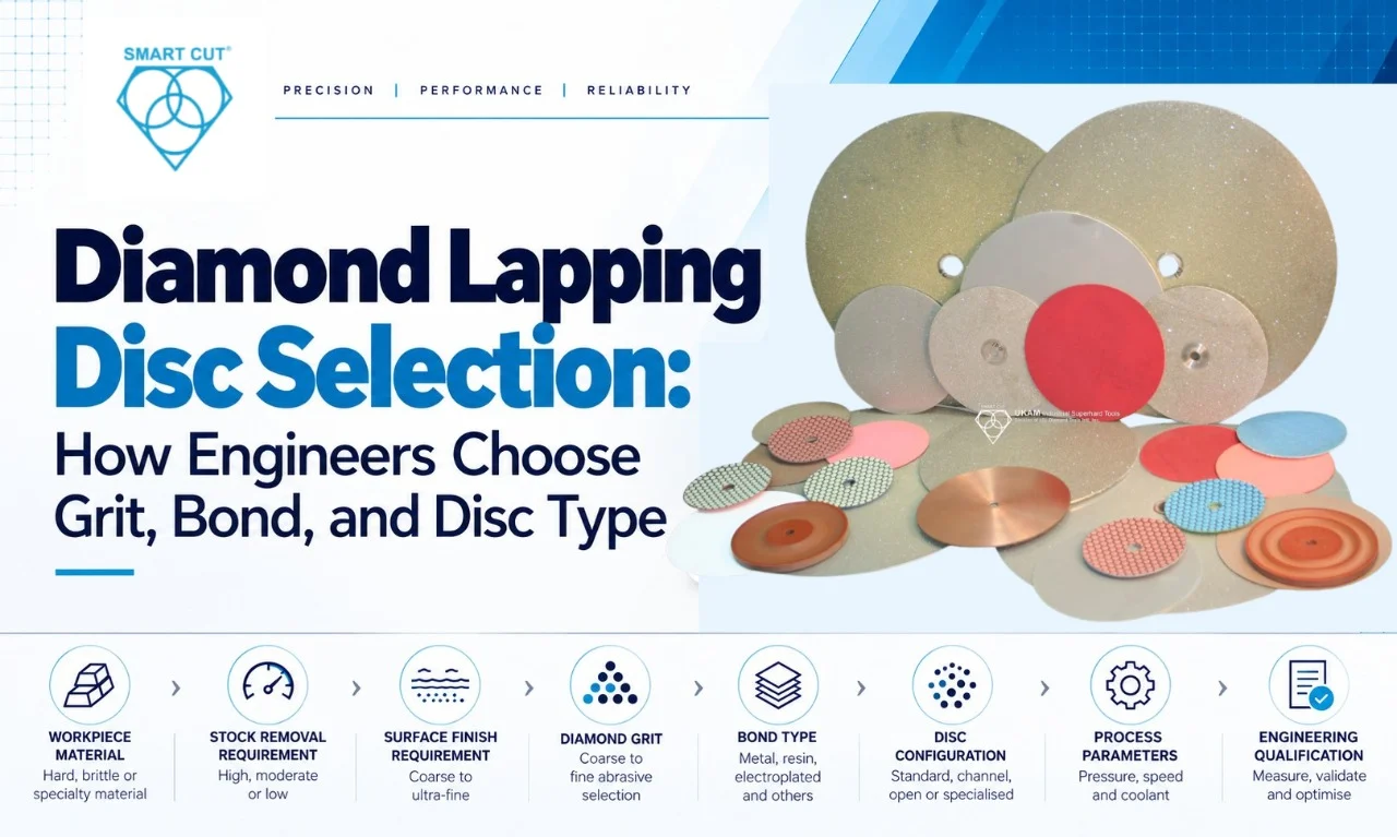
Table of Contents
Toggle
American Based Manufacturer

Established in 1990


Custom manufacturing


Selecting a diamond lapping disc is a process engineering decision, not simply a grit selection exercise. The wrong combination of abrasive size, bond behavior, disc configuration, pressure, speed, coolant, and material can increase cycle time, generate subsurface damage, accelerate disc wear, or produce an unstable surface finish.
For production and laboratory applications, engineers should select the disc against measurable process requirements:
- Material removal rate
- Dimensional tolerance
- Surface finish
- Subsurface damage
- Edge quality
- Disc life
- Changeover frequency
- Cost per accepted part
A disc with a lower purchase price is not necessarily the lower cost option if it produces more scrap, shorter tool life, or longer cycle times.
Why Engineers Revisit Diamond Lapping Disc Selection
Diamond lapping disc selection normally comes under review when the existing process stops meeting one or more production requirements.
|
Production trigger |
What the engineer should investigate |
|---|---|
|
Cycle time has increased |
Disc loading, glazing, abrasive exposure, pressure, speed |
|
Surface finish has degraded |
Grit condition, disc wear, contamination, process stability |
|
Edges are chipping |
Grit severity, pressure, workpiece support |
|
Material removal has slowed |
Disc loading, abrasive wear, grit or bond suitability |
|
Disc consumption has increased |
Bond wear, pressure, coolant, material interaction |
|
Dimensional variation has increased |
Disc flatness, platen condition, uneven wear, workpiece loading |
|
Scrap rate has increased |
Subsurface damage, thermal effects, contamination, operator variation |
The first step should be measurement rather than immediate tooling replacement.
Establish a Baseline Before Changing the Disc
Record the existing process before running a qualification trial.
|
Parameter |
Baseline value to record |
|---|---|
|
Material |
Grade and condition |
|
Starting thickness |
Actual measured value |
|
Target thickness |
Required final value |
|
Stock removal |
Starting thickness minus final thickness |
|
Disc grit |
Mesh or micron specification |
|
Disc type |
Metal bond, resin bond, electroplated, channel, or other |
|
Bond specification |
Manufacturer designation |
|
Manufacturer specification |
|
|
Model and platen diameter |
|
|
Speed |
RPM or surface speed |
|
Applied pressure |
Actual process value |
|
Type and concentration |
|
|
Cycle time |
Time per operation |
|
Surface finish |
Ra, Rz, or application specific requirement |
|
Flatness |
Measured result |
|
Scrap |
Rejected parts per defined lot |
|
Disc life |
Parts or minutes per disc |
During qualification, change one primary variable at a time whenever practical. Changing grit, pressure, RPM, and coolant simultaneously makes the result difficult to interpret.
Engineering qualification rule
If grit is the variable under evaluation, keep pressure, speed, coolant, machine, workholding, and cycle strategy consistent.
After the grit has been qualified, evaluate pressure or speed separately.
This produces process data that can be reproduced rather than a one time trial result.
Diamond Grit Selection
Diamond grit controls the size and number of abrasive cutting points interacting with the workpiece.
A coarser abrasive generally has greater potential for stock removal, while a finer abrasive is normally selected as surface finish, dimensional control, and damage requirements become more demanding.
The correct selection depends on the complete process.
Practical Diamond Lapping Disc Selection Matrix
|
Material/process condition |
Stock removal requirement |
Finish requirement |
Initial grit direction |
Primary qualification concern |
|---|---|---|---|---|
|
Hard, high stock removal |
High |
Moderate |
Coarser |
Removal rate and disc loading |
|
Hard material, controlled removal |
Moderate |
Fine |
Intermediate |
Balance of removal and finish |
|
Moderate |
Fine |
Fine or controlled |
Edge chipping and subsurface damage |
|
|
Optical or semiconductor surface |
Low |
Very fine |
Fine |
Surface integrity and contamination |
|
Low |
Fine |
Fine |
Flatness and dimensional control |
|
|
Heavy swarf generation |
High |
Moderate |
Coarser or open configuration |
Debris evacuation |
|
Very low |
Very fine |
Fine |
Scratch depth and surface roughness |
This matrix is a starting point for qualification, not a universal grit prescription.
UKAM currently lists diamond lapping products across a broad range of mesh sizes. Current listed diamond lap products include 60, 80, 100, 180, 260, 360, 600, 1,200, and 3,000 mesh, depending on configuration.
Mesh designations should be evaluated according to the supplier’s stated specification. Engineers should not assume that two suppliers’ equivalent grit numbers will produce identical cutting behavior without qualification.
Worked engineering calculation
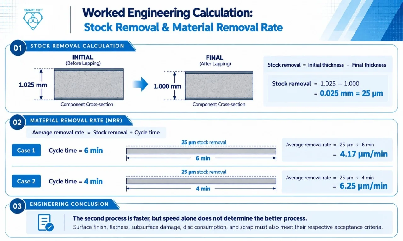
Suppose a component enters the lapping operation at:
Initial thickness = 1.025 mm
Final thickness = 1.000 mm
Required stock removal:
Stock removal = 1.025 − 1.000 = 0.025 mm
Therefore:
Stock removal = 25 µm
If the operation requires six minutes:
Average removal rate = 25 µm ÷ 6 min = 4.17 µm/min
If another disc removes the same 25 µm in four minutes:
Average removal rate = 25 µm ÷ 4 min = 6.25 µm/min
The second process is faster, but speed alone does not determine the better process. Surface finish, flatness, subsurface damage, disc consumption, and scrap must also meet their respective acceptance criteria.
Diamond Concentration
Diamond concentration affects the population of abrasive particles participating in the cutting process.
Higher concentration can influence abrasive life and cutting behavior. Lower concentration changes abrasive exposure and the interaction between individual diamond particles and the workpiece.
|
Observation |
Investigation |
|---|---|
|
Disc wears rapidly |
Review concentration, bond retention, pressure, and material interaction |
|
Cutting is excessively aggressive |
Review concentration, grit, and pressure |
|
Disc appears loaded |
Review abrasive exposure, coolant, pressure, and workpiece material |
|
Surface finish is unstable |
Review concentration, grit, disc condition, and contact uniformity |
|
Long disc life but low cutting efficiency |
Evaluate whether sufficient abrasive exposure is available |
Concentration should be evaluated together with grit and bond rather than selected independently.
Bond Selection
The bond determines how firmly diamond particles are retained and how the abrasive surface develops during use.
The engineering objective is not maximum diamond retention. The process requires an appropriate balance between abrasive retention and exposure.
|
Bond characteristic |
Process implication |
|---|---|
|
Higher retention |
Longer abrasive retention, potentially lower abrasive release |
|
Lower retention |
Greater potential for abrasive exposure, potentially higher wear |
|
Rigid structure |
Strong dimensional support, depending on configuration |
|
More yielding structure |
Different contact and finishing behavior |
|
Strong retention of a plated diamond layer |
|
|
Different abrasive release and finishing characteristics |
|
|
Diamond retained within a metal matrix |
A useful selection chain is:
Diamond retention → abrasive exposure → cutting efficiency → disc wear → surface result
Bond selection should therefore be based on the required process behavior rather than tool life alone.
Disc Configuration Selection
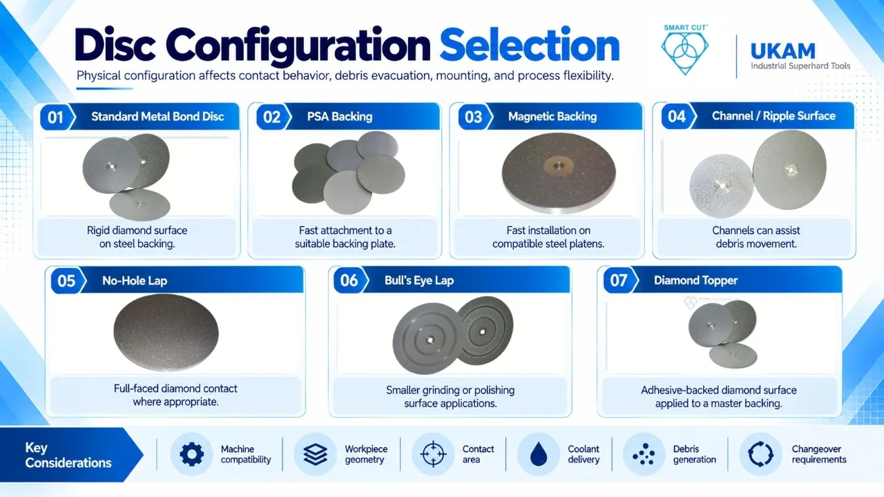
Physical configuration affects contact behavior, debris evacuation, mounting, and process flexibility.
|
Configuration |
Engineering consideration |
|---|---|
|
Standard metal bond disc |
Rigid diamond surface on steel backing |
|
Fast attachment to a suitable backing plate |
|
|
Fast installation on compatible steel platens |
|
|
Channel or ripple surface |
Channels can assist debris movement |
|
Full faced diamond contact where appropriate |
|
|
Bull's Eye Lap |
Smaller grinding or polishing surface applications |
|
Adhesive backed diamond surface applied to a master backing |
The correct configuration depends on machine compatibility, workpiece geometry, contact area, coolant delivery, debris generation, and changeover requirements.
Pressure, Speed, and Coolant
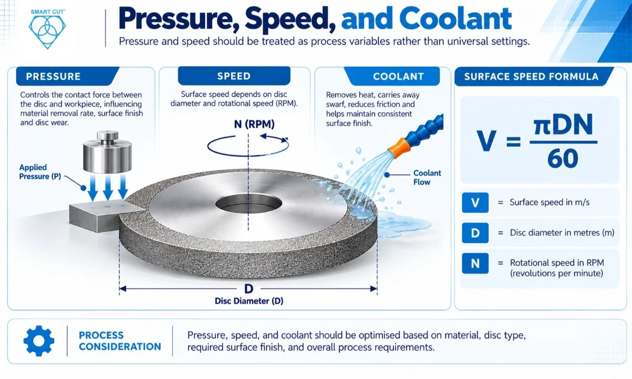
Pressure and speed should be treated as process variables rather than universal settings.
For a rotating disc:
Surface speed = πDN
Using metric units:
V = πDN / 60
Where:
V = surface speed in m/s
D = disc diameter in metres
N = RPM
The same RPM does not produce the same surface speed on different disc diameters.
Pressure affects abrasive and workpiece interaction. Excessive pressure can increase heat generation, abrasive wear, loading, edge damage, and subsurface damage. Insufficient pressure can reduce cutting efficiency.
Coolant can:
- Remove heat
- Carry away swarf
- Reduce friction
- Control surface temperature
- Reduce loading in appropriate applications
Operating values should be selected according to the specific disc, machine, workpiece, diameter, and manufacturer’s recommendations.
Important Engineering Formulas
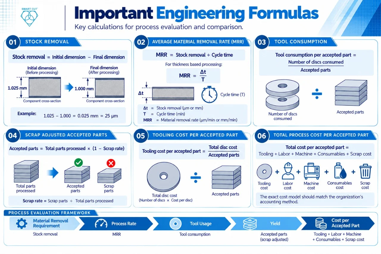
Stock removal
Stock removal = Initial dimension − Final dimension
Average material removal rate
MRR = Stock removal ÷ Cycle time
For thickness based processing:
MRR = Δt / T
Tool consumption
Tool consumption per accepted part = Number of discs consumed ÷ Accepted parts
Scrap adjusted accepted parts
Accepted parts = Total parts processed × (1 − Scrap rate)
Tooling cost per accepted part
Tooling cost per accepted part = Total disc cost ÷ Accepted parts
Total process cost per accepted part
Total cost per accepted part = Tooling + Labor + Machine + Consumables + Scrap cost
The exact cost model should match the organization’s accounting method.
Cost Per Part Comparison
The following numbers are illustrative engineering values, not UKAM pricing or production data.
|
Metric |
Supplier A |
Supplier B |
|---|---|---|
|
Disc price |
$90 |
$120 |
|
Parts per disc |
180 |
300 |
|
4 |
2 |
|
|
Cycle time |
7.0 min |
5.5 min |
|
Scrap rate |
4.0% |
1.5% |
|
Accepted parts from 1,000 processed |
960 |
985 |
|
Disc consumption for 1,000 parts |
5.56 |
3.33 |
|
Approx. disc cost for 1,000 parts |
$500 |
$500 |
|
Tooling cost per accepted part |
$0.52 |
$0.41 |
The higher purchase price in this illustrative example does not translate directly into higher tooling cost. Disc life and scrap rate change the economics.
A complete production comparison should also include labor, machine time, coolant, dressing, changeover, and rejected part cost.
Step by Step Diamond Lapping Disc Qualification
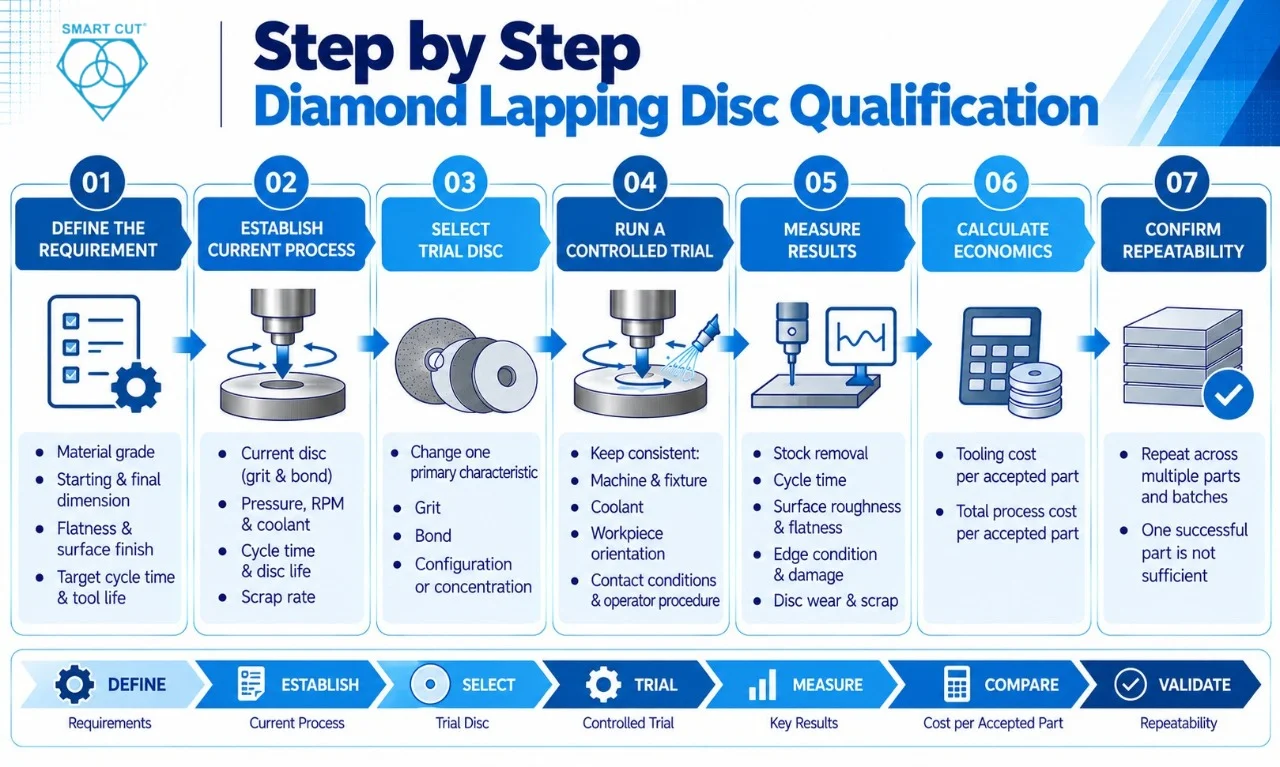
Phase 1: Define the requirement
Document:
- Material grade
- Starting dimension
- Final dimension
- Flatness
- Surface finish
- Maximum allowable damage
- Target cycle time
- Expected tool life
Phase 2: Establish the current process
Record:
- Current disc
- Grit
- Bond
- Pressure
- RPM
- Coolant
- Cycle time
- Disc life
- Scrap rate
Phase 3: Select the trial disc
Change one primary characteristic, such as:
- Grit
- Bond
- Disc configuration
- Concentration
Phase 4: Run a controlled trial
Maintain consistency in:
- Machine
- Fixture
- Coolant
- Workpiece orientation
- Contact conditions
- Operator procedure
Phase 5: Measure results
Record:
- Stock removal
- Cycle time
- Surface roughness
- Flatness
- Edge condition
- Subsurface damage
- Disc wear
- Scrap
Phase 6: Calculate economics
Compare tooling cost and total process cost per accepted part.
Phase 7: Confirm repeatability
Repeat the trial across multiple parts and, where practical, multiple batches.
A single successful part is not sufficient process qualification.
Material Specific Failure Modes
Silicon Carbide
Primary failure mode: subsurface microcracking.
Silicon carbide has high hardness and can respond poorly to aggressive contact conditions. Excessive pressure, inappropriate grit, or unstable contact can increase damage beneath the visible surface.
When subsurface integrity is critical, cross sectional inspection should be included in qualification.
Alumina
Primary failure mode: edge chipping.
Alumina can develop localized edge damage when contact pressure becomes concentrated near unsupported edges. Fine abrasive selection, adequate support, and controlled pressure can reduce this risk.
Silicon Nitride
Primary failure mode: surface microfracture.
Silicon nitride requires control of abrasive interaction because aggressive cutting conditions can produce surface defects that become visible during subsequent finishing.
Tungsten Carbide
Primary failure mode: nonuniform material removal.
Tungsten carbide components can show differences in removal behavior depending on binder content, geometry, and surface condition. Flatness and removal uniformity should therefore be evaluated alongside cycle time.
Sapphire
Primary failure mode: surface and subsurface cracking.
Sapphire is extremely hard and brittle. Aggressive abrasive interaction can create damage below the visible surface. Fine finishing stages should be qualified against both surface finish and subsurface integrity.
Fused Silica
Primary failure mode: persistent scratching and subsurface damage.
Fused silica requires careful control of abrasive size and process contamination. A single coarse particle entering a finishing stage can create a scratch that affects an otherwise acceptable surface.
Gallium Arsenide
Primary failure mode: surface damage combined with process contamination.
For semiconductor materials, surface integrity and contamination control must be evaluated together. Dedicated tooling and controlled cleaning procedures may be required depending on the application.
PCD
Primary failure mode: edge chipping or preferential binder removal.
PCD contains diamond and binder phases, so removal behavior can vary with diamond structure and binder characteristics. The process should be evaluated for edge integrity and uniform removal rather than cutting speed alone.
Common Diamond Lapping Disc Selection Mistakes
|
Mistake |
Result |
|---|---|
|
Selecting grit only by desired finish |
Removal rate may become unacceptable |
|
Selecting the most aggressive disc |
Increased damage or scrap |
|
Changing grit and pressure together |
Trial result becomes difficult to interpret |
|
Ignoring disc diameter |
Surface speed calculation becomes inaccurate |
|
Cost per accepted part may be higher |
|
|
Ignoring coolant |
Heat and loading can increase |
|
Using one disc for incompatible materials |
Cross contamination risk |
|
Measuring only cycle time |
Surface integrity problems may be missed |
|
Continuing to use a glazed disc |
Removal rate becomes unstable |
|
Failing to record disc life |
Long term tooling cost cannot be calculated |
Troubleshooting Diamond Lapping Disc Performance
|
Symptom |
Potential cause |
Corrective investigation |
|---|---|---|
|
Removal rate drops |
Loading or glazing |
Inspect disc condition and coolant |
|
Surface becomes rougher |
Abrasive damage or contamination |
Inspect disc and workpiece |
|
Disc wears rapidly |
Excessive pressure or unsuitable bond |
Review pressure and bond |
|
Edge chipping increases |
Aggressive contact |
Review grit, pressure, and support |
|
Finish varies across part |
Uneven contact or disc wear |
Check platen and wear pattern |
|
Disc loads quickly |
Disc loads quickly |
Swarf accumulation |
|
Disc loads quickly |
Swarf accumulation |
Review coolant and process |
|
New disc performs poorly |
Mounting or break in issue |
Verify mounting, flatness, and initial process |
|
Results vary between operators |
Parameter variation |
Establish controlled SOP |
Supplier Evaluation
A supplier should be able to provide more than a grit number.
|
What to ask |
What the answer reveals |
|---|---|
|
What bond is used? |
Abrasive retention behavior |
|
What diamond size is specified? |
Cutting scale |
|
What concentration is available? |
Abrasive population |
|
What backing options are available? |
Machine compatibility |
|
What materials has the disc been qualified on? |
Application experience |
|
What operating range is recommended? |
Process starting point |
|
How is disc wear measured? |
Tool life methodology |
|
Can the disc be customized? |
Ability to match process requirements |
|
Are cross reference numbers available? |
Replacement compatibility |
|
What technical support is available? |
Qualification support |
A supplier that can discuss failure modes, process variables, and qualification criteria can contribute more useful information during process development than a specification sheet alone.
UKAM SMART CUT Diamond Lapping Technology Comparison
The purpose of this comparison is to identify configuration differences and qualification considerations, not to assign a universal performance ranking.
|
UKAM configuration |
Relevant characteristic |
Primary qualification variable |
Consider when |
|---|---|---|---|
|
SMART CUT Diamond Topper |
Adhesive backed diamond surface |
Adhesion, flatness, cutting behavior |
A topper is suitable for the existing master backing |
|
Nickel bonded diamond on steel backing |
Grit, bond behavior, wear, removal rate |
Rigid diamond lapping is required |
|
|
Channel/Ripple Diamond Disc |
Textured surface with channels |
Debris evacuation and contact behavior |
Swarf management is a process concern |
|
No Hole Lap |
Full faced diamond disc |
Contact uniformity and surface result |
Full surface contact is appropriate |
|
Bull's Eye Lap |
Smaller grinding or polishing surface |
Contact area and removal uniformity |
Smaller contact areas are required |
|
PSA backing |
Adhesive attachment |
Bonding consistency and mounting |
Fast disc installation is required |
|
Magnetic backing |
Magnetic attachment |
Platen compatibility and mounting stability |
Compatible steel platen is available |
UKAM’s current product listings identify these configurations. Its current metal bond diamond disc specification lists nickel bond, steel construction, PSA or magnetic backing, 8, 10, and 12 inch diameters, and diamond sizes from 250 to 6 microns.
The appropriate configuration should still be confirmed through the application qualification process.
Qualification Acceptance Matrix
Before approving a diamond lapping disc for production, define pass/fail criteria.
|
Category |
Target |
Pass/Fail |
|---|---|---|
|
Cycle time |
≤ approved target |
|
|
Stock removal |
Within tolerance |
|
|
Surface roughness |
≤ specification |
|
|
Flatness |
Within drawing requirement |
|
|
Edge quality |
No unacceptable chips |
|
|
Subsurface damage |
Within material requirement |
|
|
Disc life |
≥ target |
|
|
Scrap rate |
≤ target |
|
|
Cost per accepted part |
≤ approved cost |
|
|
Repeatability |
Stable across trial lot |
This prevents a disc from being approved simply because it cuts faster.
Defining End of Tool Life
Disc life should have a measurable production endpoint.
Possible end of life criteria include:
- Removal rate falls below the process limit.
- Surface finish exceeds specification.
- Disc wear causes dimensional instability.
- Dressing no longer restores required performance.
- Diamond exposure becomes insufficient.
- Disc flatness becomes unacceptable.
- Scrap rate exceeds the process limit.
A practical definition is:
End of tool life = the first condition that causes the process to fail an approved acceptance criterion.
This provides a consistent basis for comparing tooling between suppliers.
Engineering Process Flow
Define material and tolerance
Measure current process
Select initial grit direction
Evaluate bond and concentration
Select disc configuration and backing
Set controlled pressure, speed, and coolant
Run qualification trial
Measure removal, finish, flatness, damage, and disc wear
Calculate cost per accepted part
Repeat for confirmation
Release process specification
This converts diamond lapping disc selection from trial and error into a controlled engineering qualification.
Frequently Asked Questions
The correct grit depends on material, stock removal, surface finish, dimensional tolerance, and acceptable damage. Coarser abrasive generally supports higher stock removal, while finer abrasive is normally used as the process moves toward tighter surface and dimensional requirements. The final selection should be confirmed through controlled testing.
No. A finer disc can reduce scratch depth and improve surface finish, but it can also reduce material removal rate and increase cycle time. Using a fine abrasive too early in the process can therefore reduce productivity.
The primary difference is abrasive retention and release behavior. Metal bond systems can provide strong diamond retention and dimensional support, while resin bond systems provide different abrasive exposure and finishing characteristics. The appropriate choice depends on material, removal rate, surface requirement, heat generation, and disc life.
Disc life should be tied to a defined process endpoint. Useful measures include accepted parts per disc, material removed per disc, operating time, or the point at which the disc can no longer meet surface finish or dimensional requirements.
Common causes include loading, glazing, insufficient abrasive exposure, unsuitable pressure, incorrect speed, inadequate coolant, or disc wear. Inspect the disc condition and process history before replacing the tooling.
Yes. Disc diameter affects surface speed at a given RPM. The same RPM on different diameter discs produces different surface velocities, so RPM should not be evaluated independently of disc diameter.
Increasing pressure can increase cutting interaction, but it can also increase heat, abrasive wear, loading, edge damage, and subsurface damage. Pressure should therefore be qualified against material response and surface requirements rather than increased simply to reduce cycle time.
A disc may process multiple materials, but dedicated tooling can be preferable when contamination, surface integrity, or material compatibility is critical. Semiconductor, optical, and other high purity applications may require stricter segregation and cleaning controls.
Engineering Principles
- Select the disc against the complete process, not grit alone.
- Establish a measurable baseline before changing tooling.
- Change one primary variable at a time during qualification.
- Match grit to stock removal and surface requirements.
- Evaluate bond according to abrasive retention and exposure.
- Treat pressure, speed, and coolant as interacting variables.
- Measure tool life using a defined production endpoint.
- Compare tooling using cost per accepted part rather than purchase price.
- Monitor subsurface damage when processing brittle and advanced materials.
- Use dedicated tooling where contamination can affect product quality.
- Confirm repeatability before releasing a new disc specification.
- Document the qualified process so results do not depend on operator preference.
Planning a Diamond Lapping Disc Qualification?
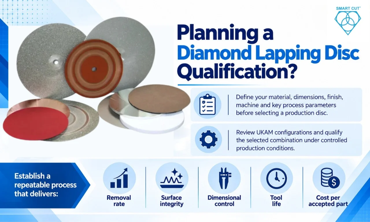
Before selecting a production disc, define the material, starting and final dimensions, required finish, flatness, machine, disc diameter, grit, bond, pressure, speed, coolant, target cycle time, and acceptance criteria.
For application specific diamond lapping disc selection, review the available UKAM configurations against those requirements and qualify the selected combination under controlled production conditions.
The objective is not simply to find a diamond lapping disc that cuts. The objective is to establish a repeatable process that delivers the required removal rate, surface integrity, dimensional control, tool life, and cost per accepted part.
Trusted by Tens of Thousands of Manufacturers, Laboratories,
Research Institutions Worldwide Since 1990
American Based Manufacturer
Established in 1990
