








































Incoming Diamond Blade Inspection and Trial-Cut Checklist

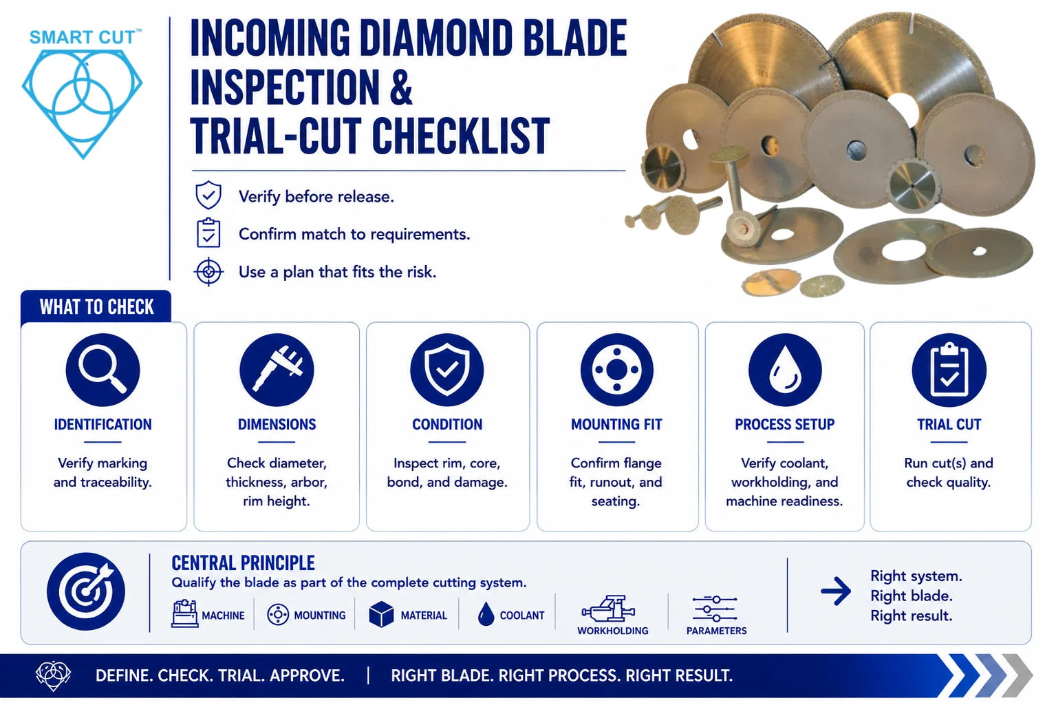
Table of Contents
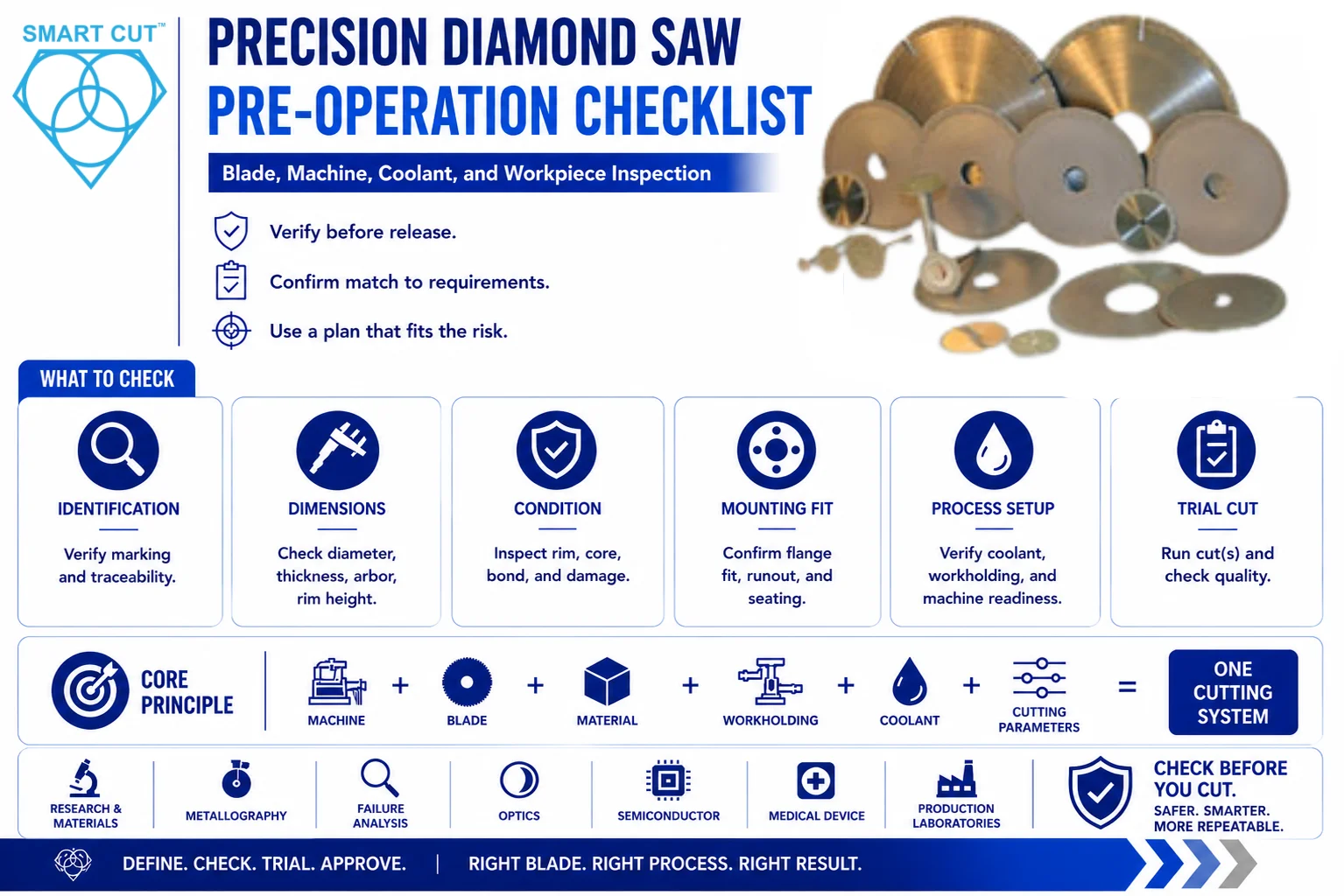
ToggleFor new, changed, high-value, or process-critical applications, incoming verification and a controlled trial cut can reduce risk before a diamond blade is released for regular production. The goal is not to impose one universal test on every blade. The goal is to confirm that the received blade matches the approved requirements and that the complete cutting process can produce the required result under defined conditions.
A useful acceptance plan is proportional to risk. It may be limited to identification and dimensional checks for a stable, previously qualified process, or it may include a documented series of trial cuts for a new or demanding application. In either case, the plan should state what will be checked, how it will be measured, and who can approve the result.
Central principle: Qualify the blade as part of the complete cutting system. A blade can meet its dimensional requirements and still produce unacceptable results when the machine, mounting, material, coolant, workholding, or operating parameters are not suitable for the application.
Trusted by Tens of Thousands of Manufacturers, Laboratories Research Institutions Worldwide Since 1990

American Based Manufacturer

Established in 1990


Custom manufacturing


| Stage | Primary question | Typical timing |
|---|---|---|
| Incoming inspection | Does the received blade match the approved identification, dimensions, condition, and mounting requirements? | Before installation |
| Trial-cut qualification | Can the blade and configured cutting process produce the required result under controlled, production-representative conditions? | Before production release when qualification is required |
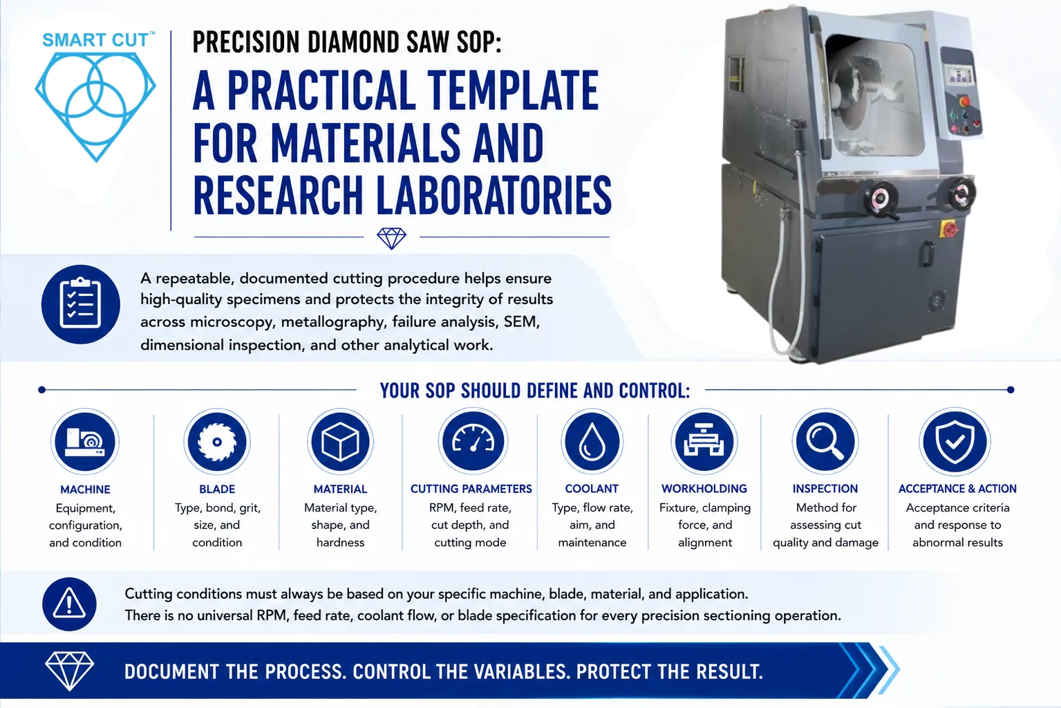
This procedure is intended for precision diamond blades used on controlled cutting equipment. It can be adapted to thin continuous-rim blades, slotted or segmented constructions, hub-mounted blades, and other application-specific designs. Not every inspection applies to every construction. For example, a flexible ultra-thin blade requires different handling and measurement pressure than a rigid metal-core blade, while a blade with a keyed or proprietary mounting interface requires checks that may not apply to a plain arbor hole.
Use the approved blade drawing, product documentation, machine manual, and internal quality procedure to decide which characteristics are mandatory. The checklist does not create universal tolerances for outside diameter, thickness, flatness, runout, kerf, chipping, surface finish, or blade life. Those limits depend on the blade design, equipment, material, part requirements, and qualified process.
When is trial-cut qualification appropriate?
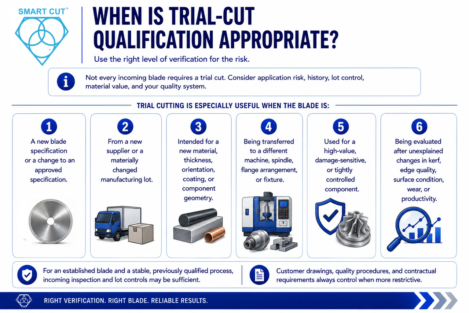
Not every incoming blade requires a separate trial cut. The level of verification should reflect application risk, qualification history, lot control, material value, and the organization’s quality system. Trial cutting is especially useful when the blade is:
- A new blade specification or a change to an approved specification
- From a new supplier or a materially changed manufacturing lot
- Intended for a new material, thickness, orientation, coating, or component geometry
- Being transferred to a different machine, spindle, flange arrangement, or fixture
- Used for a high-value, damage-sensitive, or tightly controlled component
- Being evaluated after unexplained changes in kerf, edge quality, surface condition, wear, or productivity
For an established blade and a stable, previously qualified process, documented incoming inspection and lot controls may be sufficient. The customer’s drawings, quality procedures, and contractual requirements always control when they are more restrictive.
Seven-step incoming inspection and trial-cut procedure
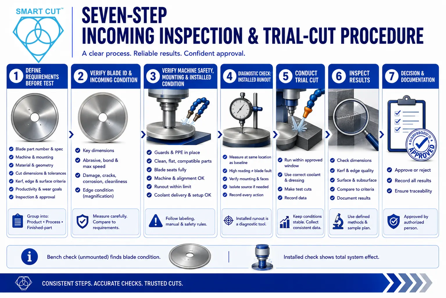
Step 1: Define requirements before opening the test
Document the intended application and acceptance basis before reviewing the cutting results. This prevents the criteria from changing after the outcome is known.
- Approved blade part number and specification
- Machine identification and mounting configuration
- Material type, grade, lot, thickness, geometry, and orientation
- Required cut dimensions and dimensional tolerances
- Acceptable kerf, edge condition, surface condition, and subsurface condition where applicable
- Productivity, material-loss, and blade-wear requirements
- Inspection methods, measurement locations, sampling requirements, and approval authority
Separate the requirements into three groups. Product requirements define what the blade must physically match. Process requirements define the machine and operating window in which it will be evaluated. Finished-part requirements define the cut result that must be achieved. This separation makes it easier to determine whether a nonconformance belongs to the received blade, the test setup, or the cutting process.
Important: Do not create arbitrary numerical limits when the approved drawing, customer specification, or qualified process does not contain them. Establish a documented baseline or obtain engineering approval for proposed criteria.
Step 2: Verify blade identification and incoming condition
Match the blade and its documentation to the purchase order, approved drawing, product specification, or internal purchasing record. Record the supplier lot, batch, serial identification, or package traceability when available.
- Outside diameter, cutting edge thickness, arbor or mounting interface, hub dimensions, and other specified geometry
- Abrasive type, grit, bond or construction, concentration, and maximum operating speed where documented
- Cracks, chips, distortion, corrosion, contamination, damaged mounting surfaces, and packaging damage
- Cutting edge condition under suitable magnification when blade size and application risk require it
Use a measurement method that will not damage an ultra-thin blade or deform its cutting edge. Compare each measurement with an approved requirement. The physical cutting edge thickness and the resulting kerf are separate characteristics and should not be treated as interchangeable measurements.
Measurement practice for thin or precision blades
Support the blade so it is not bent by its own weight or by the measuring tool. Apply only the contact force appropriate for the blade construction. When thickness varies by location, define whether measurements are taken at the core, hub, abrasive rim, or another specified feature. Record the instrument, resolution, measurement locations, and observed range rather than retaining only one convenient value.
A bench inspection of the unmounted blade and an installed runout check serve different purposes. Bench measurements can identify incoming geometry or damage. Installed measurements show the combined effect of the blade, arbor, flanges, spindle, cleanliness, and mounting practice.
Step 3: Verify machine safety, mounting, and installed condition
Before mounting or operating the blade, follow the blade labeling, machine manual, facility safety procedures, and applicable requirements. Confirm that the intended spindle speed does not exceed the blade’s documented maximum operating speed. Confirm the specified rotation direction where one is marked or documented.
- Machine guard and required protective equipment are in place
- Arbor, flanges, spacers, hub interface, and mounting surfaces are clean, flat, undamaged, and compatible
- The blade seats fully without forcing, excessive clearance, or trapped contamination
- Spindle condition, machine alignment, bearings, feed motion, and workholding are suitable for the test
- Installed-blade axial or lateral runout is checked against the applicable machine or process requirement
- Coolant delivery, concentration, filtration, temperature, and nozzle position are appropriate for the blade and material
Safety note: This guide provides general technical information. It does not replace the blade manufacturer’s instructions, the machine manual, operator training, a workplace risk assessment, or applicable safety requirements.
Use installed runout as a diagnostic check
Measure installed runout at a defined location and with the same setup used for the approved baseline. A high reading does not by itself identify the blade as the cause. First verify that the mounting faces are clean, the flange arrangement is correct, and the indicator setup is stable. If permitted by the equipment and procedure, remounting the blade or checking the spindle and flange separately can help isolate the source. Record each action so an improved reading is not mistaken for an unexplained change.
Do not attempt to correct runout by forcing the blade, over-tightening fasteners, or using unapproved shims. Any adjustment must follow the machine and mounting-system instructions.
Step 4: Prepare representative material, workholding, and metrology
The trial material should represent production as closely as practical. Differences in grade, lot, thickness, orientation, coating, prior processing, or internal structure can change cutting behavior. The fixture should reproduce the production support and exit condition without allowing movement or stressing the component.
Select measurement equipment before cutting. Equipment resolution and uncertainty must be suitable for the required tolerance. Use calibrated or otherwise controlled equipment when required by the organization’s quality system. Keep magnification, lighting, sample preparation, inspection locations, and measurement methods consistent between the candidate blade and the approved baseline.
Prepare enough representative material to complete conditioning, preliminary cuts, and the planned repeatability check without changing lots midway through the evaluation. Mark samples so each measured result can be traced to its cut order and process record. When the production component is too valuable for initial testing, use a representative coupon first, then confirm the result on the actual part geometry before unrestricted release.
Step 5: Condition the blade when required and perform controlled trial cuts
Some precision diamond blades require dressing or conditioning to expose the abrasive and establish stable cutting behavior. Follow the applicable blade instructions. Record any dressing stick, dressing method, duration, depth, or number of conditioning cuts used before evaluation.
Begin with previously qualified parameters when they apply to the same blade, machine, material, and application. Otherwise, use a documented engineering starting point. Record:
- Actual spindle speed and blade surface speed where used
- Feed rate or feed load, cutting depth, number of passes, and cutting direction
- Blade exposure beyond the flange or hub where relevant
- Coolant product, concentration, flow, filtration, temperature, and nozzle position
- Workholding method, operator, material identification, and test sequence
- Cutting time, spindle load or cutting resistance when available, noise, vibration, heat, and visible process instability
Controlled adjustment: Change one significant variable at a time whenever practical. If speed, feed, coolant, fixture, material, and blade are changed together, the result cannot reliably identify which change affected performance.
Use a planned test sequence
A controlled sequence helps distinguish normal break-in from unstable performance. The exact sequence depends on the application, but it should normally identify:
- Conditioning or dressing cuts that are excluded from acceptance measurements
- Preliminary cuts used to confirm safe operation, coolant delivery, and stable workholding
- Measured cuts made at the approved starting parameters
- Repeat cuts used to evaluate variation over time rather than one isolated result
- Any deliberate parameter change, including its reason and the cut on which it began
Stop the test if there is abnormal vibration, noise, heat, visible blade damage, loss of coolant, workpiece movement, or another unsafe condition. Preserve the last valid setup and observations before troubleshooting. A stopped test should be documented as incomplete or held for investigation, not forced into an accept or reject decision.
Step 6: Measure cut quality and demonstrate repeatability
Do not release a new blade based only on one favorable cut when production risk is meaningful. Predetermine the number of trial pieces or cuts. Increase the test quantity when material variation, component value, production volume, or process criticality is high. If a formal sampling plan applies, follow that plan instead of inventing an informal sample size.
| Characteristic | What to evaluate | Control needed for comparison |
|---|---|---|
| Edge integrity | Chipping, cracking, breakout, fracture propagation, and damage pattern | Use consistent magnification and inspect defined entry, middle, exit, or other representative locations |
| Kerf | Average width, variation along the cut, and variation between samples | Use the same optical or dimensional method and distinguish kerf from physical blade thickness |
| Dimensional result | Cut location, straightness, thickness, flatness, parallelism, and repeatability where required | Use equipment and resolution appropriate to the tolerance |
| Surface and subsurface condition | Scratches, pullout, smearing, roughness, thermal damage, and damage below the visible surface | Use the same preparation, profilometry, microscopy, or cross-sectional method |
| Blade condition | Loading, glazing, side wear, loss of cutting efficiency, change in kerf, and visible damage | Record condition before and after the test and include dressing history |
| Process result | Cutting time, material loss, yield, operator intervention, and downstream processing | Compare results under equivalent machine, material, coolant, and workholding conditions |
When a result differs from the approved baseline, determine whether the pattern follows the blade, machine, material, fixture, coolant, or operating condition. A failed trial is a diagnostic event. It is not automatic proof that the blade is defective.
Interpret the pattern, not one isolated number
Compare the location and direction of each defect with the cut sequence. Entry-edge chipping, exit breakout, periodic marks, taper, wandering, and progressive kerf change can point to different parts of the system. A defect that repeats at the same position on every sample may be related to support, entry or exit conditions, or machine motion. A result that worsens with cut count may indicate loading, glazing, insufficient conditioning, coolant loss, wear, or changing material response.
Review productivity together with quality. A faster cut is not an improvement if it increases chipping, material loss, downstream finishing, or blade consumption. Likewise, a very slow cut may look acceptable on one sample but fail the production requirement. The acceptance decision should reflect the required balance of dimensional accuracy, edge and surface integrity, repeatability, throughput, yield, and blade usage.
Step 7: Document the decision and production release
Evaluate the complete result against the criteria established before testing. Record one of three controlled outcomes:
- Accepted: The blade meets the defined requirements and is released for the qualified machine, material, and process conditions.
- Conditionally accepted: The blade is approved only within documented limitations, additional monitoring, a restricted material range, a defined parameter range, or a limited production evaluation.
- Rejected or held for investigation: The blade does not meet the applicable specification, is damaged or incompatible, produces unacceptable results under a valid controlled test, or requires additional investigation before disposition.
Before rejecting a blade for cutting performance, confirm that the machine setup, material, fixture, coolant, operating parameters, measurement method, and test execution were valid. Document the reason for rejection or hold and preserve supporting measurements and photographs.
Conditional acceptance must be specific enough to control production. State the approved machine, material range, parameter window, monitoring frequency, production quantity, and expiration or review point. If those conditions change, the conditional approval no longer demonstrates that the process remains qualified.
| Record category | Information to retain |
|---|---|
| Blade | Manufacturer, UKAM or customer part number, approved specification, lot or batch, incoming measurements, and pre-test condition |
| Machine and mounting | Machine identification, spindle, arbor, flanges, spacers, installed runout, guard, and relevant configuration |
| Material | Type, grade, lot, thickness, geometry, orientation, coating, and prior processing where relevant |
| Process | Speed, feed, depth, passes, blade exposure, cutting direction, conditioning, coolant, workholding, and cutting time |
| Inspection | Measurement equipment, magnification, inspection locations, measured results, photographs, and applicable acceptance criteria |
| Decision | Accepted, conditionally accepted, rejected, or held, including limitations, approver, approval date, and test identification |
Lot acceptance and sampling
A qualification test on one blade does not automatically establish conformity for every blade in a large incoming lot. Lot acceptance should follow the approved sampling plan, customer requirement, internal quality procedure, and the demonstrated consistency of the supplier and process.
For stable, qualified production, the plan may combine document review, dimensional or visual sampling, lot traceability, and periodic performance verification. For a new supplier, changed process, critical application, or history of variation, more extensive verification may be justified. Do not assign an arbitrary AQL or lot-acceptance rule without quality-engineering and customer approval where required.
Define the lot before sampling. Record the quantity, lot or batch identification, packaging groups, and any mixed dates or manufacturing identifiers. Select samples so they represent the lot rather than only the easiest packages to reach. If one sample fails, follow the approved escalation rule for additional inspection, containment, supplier notification, or lot disposition. Do not quietly replace the failed sample with another blade and report only the passing result.
Illustrative qualification example
A facility receives a new lot of thin diamond blades for cutting a brittle technical material. The blades pass identification and dimensional inspection. After installation, the first blade shows higher runout and more exit-edge chipping than the approved baseline. The team cleans the mounting faces, verifies the flange arrangement, remounts the blade, and repeats the installed measurement. Runout returns to the established range. The blade is then conditioned according to the applicable procedure, and a planned series of cuts is completed using the same material lot, fixture, coolant, speed, feed, and inspection method as the baseline.
The repeated cuts meet the defined kerf, edge-condition, and dimensional requirements, so the blade is accepted. The record includes the initial observation and corrective setup actions. This example is illustrative. It shows why acceptance testing should preserve both the first result and the controlled investigation instead of treating the initial poor cut as automatic proof of a defective blade.
When is requalification needed?
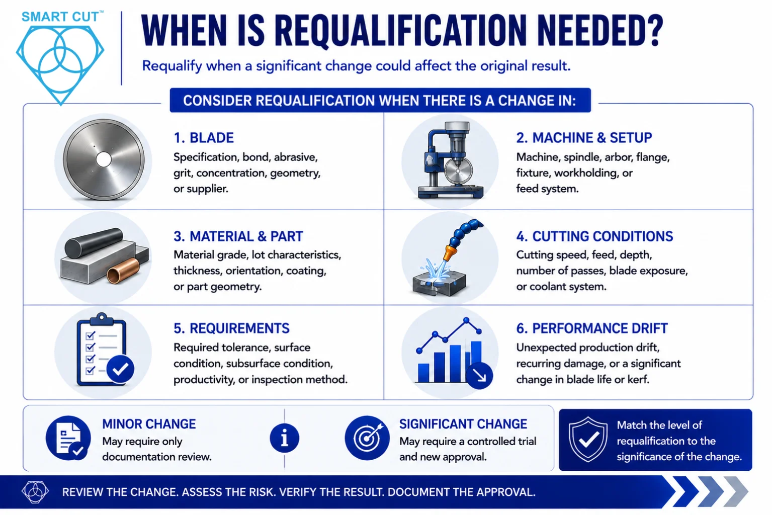
Requalification should be considered when a significant change could affect the original result, including:
- Blade specification, bond, abrasive, grit, concentration, geometry, or supplier
- Machine, spindle, arbor, flange, fixture, workholding, or feed system
- Material grade, lot characteristics, thickness, orientation, coating, or part geometry
- Cutting speed, feed, depth, number of passes, blade exposure, or coolant system
- Required tolerance, surface condition, subsurface condition, productivity, or inspection method
- Unexpected production drift, recurring damage, or a significant change in blade life or kerf
The level of requalification should reflect the significance of the change. A minor administrative change may require only documentation review. A change affecting the cutting interface or the required result may require a controlled trial and new approval.
Common acceptance-testing mistakes
- Treating visual inspection as proof of production performance
- Starting the test without defined acceptance criteria
- Using material or workholding that does not represent production
- Testing on a machine with unresolved runout, vibration, alignment, or coolant problems
- Changing several process variables at the same time
- Judging the blade from one cut, one measurement, or one location
- Measuring blade life without considering cut quality, material yield, productivity, and downstream processing
- Releasing the blade without linking approval to the qualified machine, material, process, and inspection conditions
Related UKAM technical resources
Why the Same Diamond Blade Performs Differently on Different Machines, Materials, and Applications explains how to separate blade, machine, material, and process causes during troubleshooting.
How to Properly Use Precision Diamond and CBN Blades provides additional guidance on operating speed, coolant, dressing, and blade use.
The most useful acceptance procedure reflects the actual blade, machine, material, workholding, coolant, and finished-part requirements. UKAM Industrial Superhard Tools can assist with blade selection, trial-cut planning, process variables, and the information needed to evaluate a demanding precision cutting application.
RELATED ARTICLES

Careful sample preparation is the key to good metallographic analysis. Although equipment features and process conditions are significant factors, the impact
