








































Diamond Dicing Blades: How to Select and Qualify the Complete Dicing Process

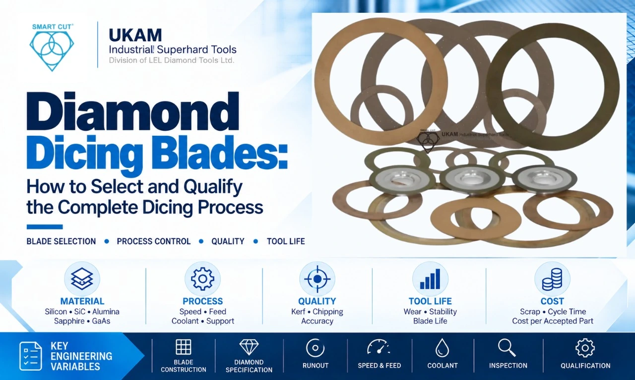
Table of Contents
Toggle
American Based Manufacturer

Established in 1990


Custom manufacturing


Start With the Dicing Requirement, Not the Blade
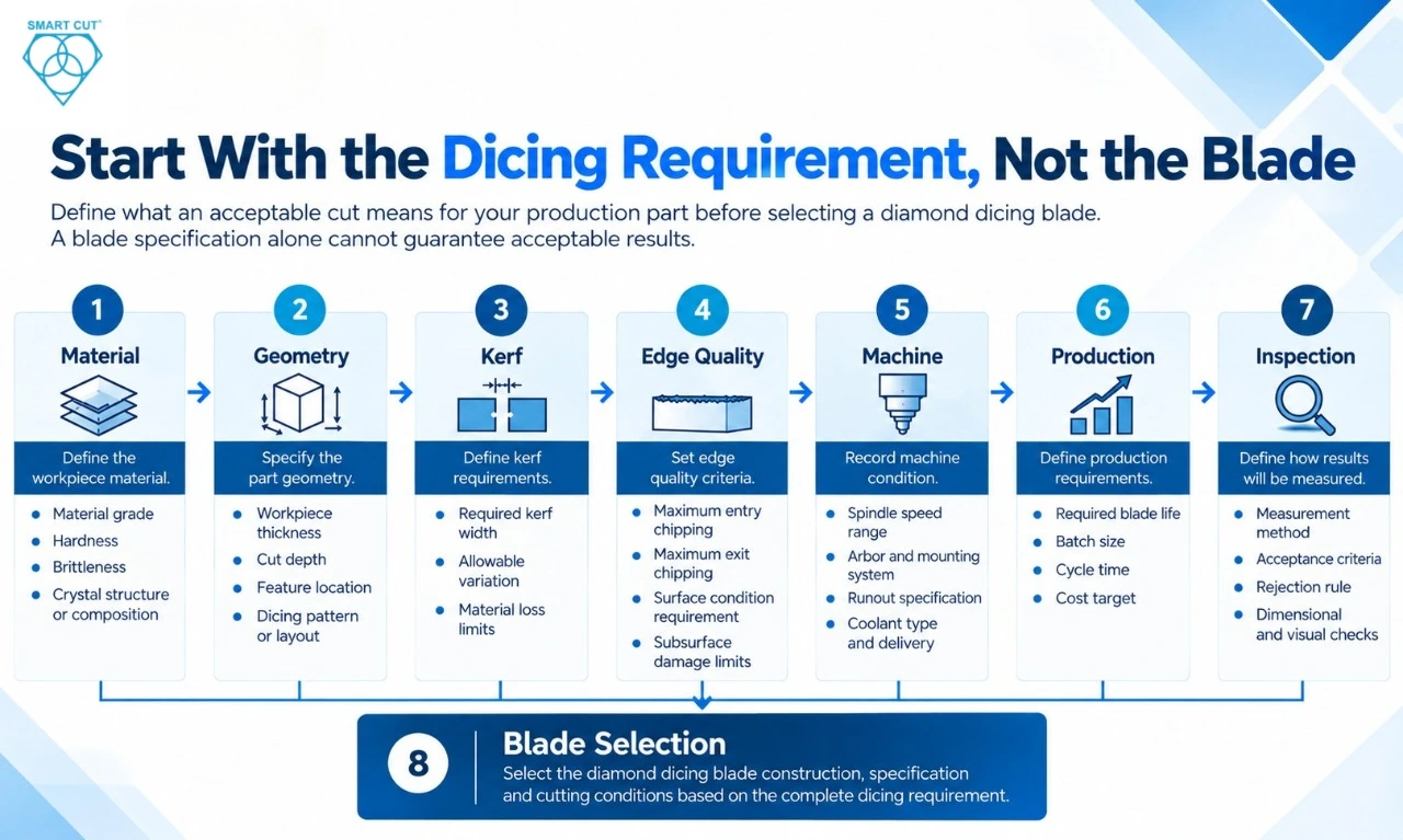
Chipping, excessive kerf, blade wear, dimensional drift and subsurface damage rarely come from one variable alone. A blade can appear suitable from its specification and still produce unacceptable results because the material, machine, mounting condition, spindle runout, feed, coolant, workholding or inspection method differs from the condition used during selection.
The first engineering step is to define what an acceptable cut means for the actual production part.
Record the material grade, workpiece thickness, cut depth, required kerf, allowable edge damage, dimensional tolerance, surface condition, production quantity and inspection method. Useful blade life ends when the defined quality requirement is no longer met, even if the blade can still physically make a cut.
The client reference methodology follows the same principle for precision drilling. Tool selection starts with the hole requirement, machine condition, inspection criteria and production requirement rather than selecting a tool from diameter alone.
Dicing Requirement Baseline
|
Parameter |
Record before blade selection |
Why it matters |
|---|---|---|
|
Material |
Grade, hardness, brittleness and structure |
Influences fracture and abrasive interaction |
|
Geometry |
Thickness, cut depth and feature location |
Influences blade exposure and stability |
|
Kerf |
Required kerf and allowable variation |
Controls material loss and dimensional accuracy |
|
Edge quality |
Maximum entry and exit chipping |
Defines the acceptance limit |
|
Spindle speed, arbor, runout and coolant |
Establishes process capability |
|
|
Production |
Required blade life and batch size |
Defines economic qualification |
|
Inspection |
Measurement method and rejection rule |
Makes comparisons reproducible |
Establish a Baseline Before Changing the Blade
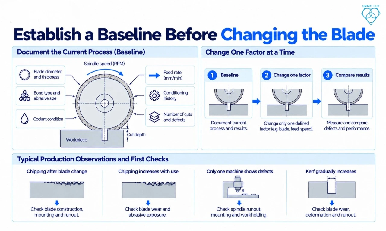
A blade comparison has value only when the existing process is documented.
Record the current blade diameter, thickness, bond, abrasive size, concentration when available, spindle speed, feed rate, cut depth, coolant condition, conditioning history, number of cuts and measured defects.
If the existing process produces acceptable parts, use it as the reference condition. During screening, change one defined factor at a time. Changing the blade, feed and spindle speed simultaneously may improve the result, but it does not identify which change produced the improvement.
Production Symptoms and First Checks
|
Production observation |
First verification |
|---|---|
|
Chipping begins after a blade change |
|
|
Chipping increases as blade life progresses |
Blade wear and abrasive exposure |
|
Only one machine produces the defect |
Spindle runout, mounting and workholding |
|
Different blades fail on the same material |
Material condition and machine capability |
|
Results change between material batches |
Material hardness, thickness or internal structure |
|
Kerf gradually increases |
Blade wear, deformation and runout |
|
Cutting load increases |
Blade loading, bond condition and coolant delivery |
The purpose of this stage is not to identify a cause immediately. It is to determine which variables should be controlled during the next comparison.
Select Blade Construction From the Material and Failure Requirement
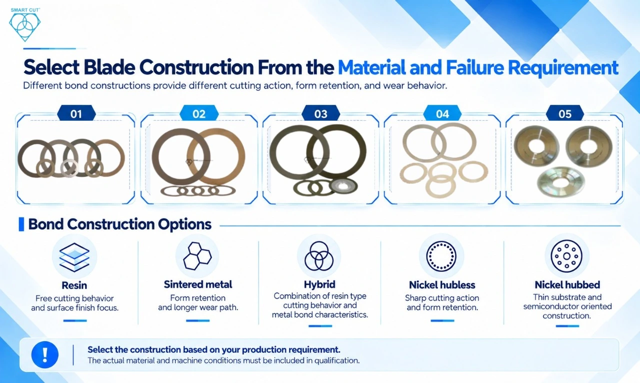
Diamond dicing blades are available in different bond constructions because the cutting process requires different combinations of abrasive exposure, form retention, cutting action and wear behavior.
UKAM currently lists resin, sintered metal, hybrid, nickel hubless and nickel hubbed dicing blade constructions. Its published descriptions associate these constructions with different cutting and wear characteristics and different application categories.
The selection should therefore begin with the production requirement rather than with a statement that one bond is universally better.
Bond Construction Reference
|
Bond construction |
General characteristic |
Qualification question |
|---|---|---|
|
Free cutting behavior and surface finish focus |
Does the cut quality justify the demonstrated wear rate? |
|
|
Form retention and longer wear path |
Can the material be cut without unacceptable edge damage or load? |
|
|
Combination of resin type cutting behavior and metal bond wear characteristics |
Does the combined behavior improve the limiting production variable? |
|
|
Sharp cutting action and form retention |
Can kerf and edge quality remain stable through useful blade life? |
|
|
Nickel hubbed |
Thin substrate and semiconductor oriented construction |
Can the required kerf and dimensional stability be maintained? |
No construction should be released to production based only on its general category. The actual material and machine conditions must be included in qualification.
Match Diamond Size, Concentration and Blade Thickness
Bond selection is only one part of blade specification. Diamond size, concentration and blade thickness also affect the cutting process.
A finer abrasive size may be considered when surface condition and edge integrity are the primary requirements. A coarser abrasive may be considered when material removal is limiting the process. The actual response depends on material, bond structure, cutting speed, feed and coolant.
Diamond concentration also changes the available abrasive population within the working zone. Higher concentration does not automatically mean better performance. It must be evaluated against cutting load, wear and the required cutting behavior.
Blade thickness directly affects kerf. Reducing thickness can reduce material loss, but thinner blades can also become more sensitive to mounting condition, runout, lateral stability and workpiece support.
Specification Decision Table
|
Variable |
Possible benefit |
Risk if selected without qualification |
|---|---|---|
|
Finer diamond size |
Lower surface damage |
Reduced material removal capability |
|
Coarser diamond size |
Higher cutting capability |
Increased edge damage |
|
Higher concentration |
Greater abrasive availability |
Increased cutting load in some conditions |
|
Lower concentration |
More open cutting behavior |
Reduced useful life in some conditions |
|
Thinner blade |
Lower kerf |
Greater sensitivity to runout and stability |
|
Greater exposure |
Deeper cutting capability |
Increased lateral deflection |
The specification should therefore be treated as a complete system rather than a single grit or bond selection.
Blade Specification Record
Before a production trial, document the complete blade specification.
|
Blade parameter |
Record |
|---|---|
|
Outside diameter |
Actual value |
|
Inside diameter |
Actual value |
|
Blade thickness |
Actual value |
|
Bond construction |
Actual specification |
|
Diamond size |
Actual specification |
|
Diamond concentration |
Actual specification when available |
|
Hub type |
Hubbed or hubless |
|
Blade exposure |
Actual value |
|
Maximum operating speed |
Manufacturer specification |
|
Conditioning method |
Actual production method |
This record prevents a common qualification problem where two blades are described simply as “diamond blades” even though their construction and operating conditions are different.
Check Runout, Mounting and Blade Exposure
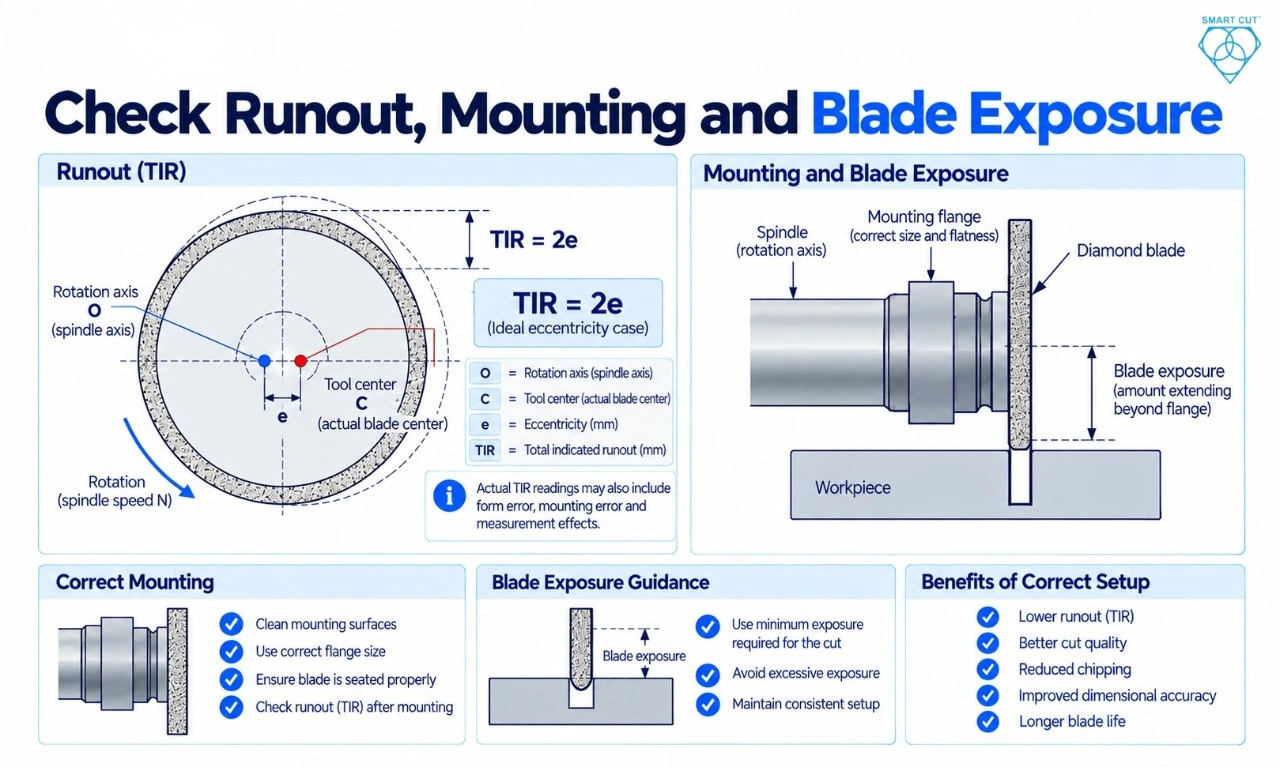
Runout should be measured rather than inferred from the cut.
Record where the measurement is taken, the gauge method and the mounting condition. A blade that measures acceptably before mounting can show a different condition after assembly on the arbor or hub.
Blade exposure also affects stability. Excessive exposure can increase lateral deflection. Insufficient exposure can prevent the blade from reaching the required cut depth.
Workholding must resist movement without distorting the workpiece.
The machine is part of the cutting system. A blade specification cannot compensate for unacceptable spindle runout, poor mounting, unstable workholding or incorrect machine conditions.
Engineering Checks
|
Check |
Record |
|---|---|
|
Spindle runout |
Measured value |
|
Blade runout |
Measured value |
|
Arbor condition |
Cleanliness and damage |
|
Flatness and contact |
|
|
Blade exposure |
Actual value |
|
Workholding |
Method and support condition |
|
Blade mounting |
Assembly procedure |
Spindle Speed, Feed and Cutting Conditions
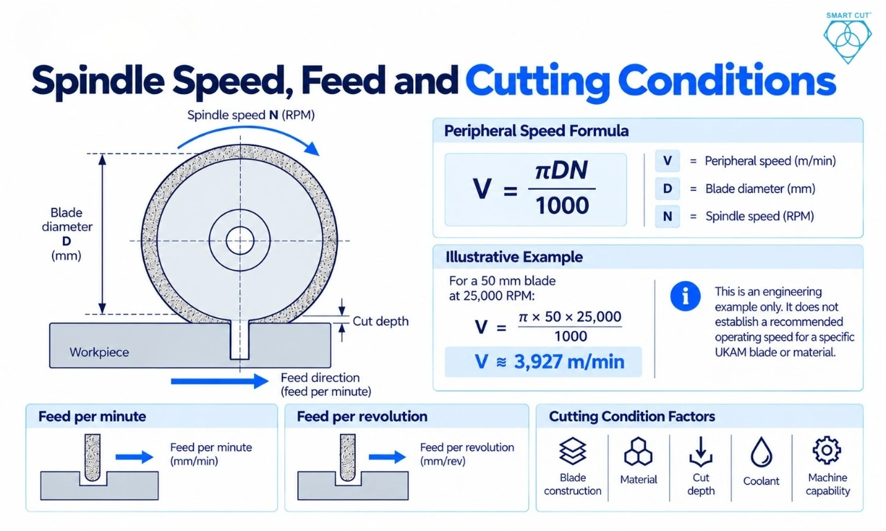
Peripheral speed can be calculated from blade diameter and spindle speed:
V = πDN / 1000
where:
V = peripheral speed in metres per minute
D = blade diameter in millimetres
N = spindle speed in revolutions per minute
Illustrative example
For a 50 mm blade operating at 25,000 RPM:
V ≈ 3,927 m/min
This calculation is an engineering example only. It does not establish a recommended operating speed for a specific UKAM blade or material.
Feed should also be recorded as feed per minute and, where useful, feed per revolution. The selected feed must be evaluated against blade construction, material, cut depth, coolant and machine capability.
Process Variables to Record
|
Variable |
Measurement |
|---|---|
|
Spindle speed |
Actual RPM |
|
Feed rate |
mm/min or mm/s |
|
Cut depth |
Programmed and measured |
|
Blade diameter |
Actual diameter |
|
Coolant |
Type, concentration and flow |
|
Conditioning |
Method and interval |
|
Workpiece support |
Coolant and Debris Removal
Coolant is part of the dicing process. It removes heat and helps transport debris away from the cutting zone.
A blocked nozzle, poor coolant direction, unstable concentration or contaminated coolant can change cutting behavior even when the blade specification remains unchanged.
For semiconductor and optical applications, record post process cleaning requirements as well. Residue or contamination may become a quality issue even when the physical cut appears acceptable.
During a controlled comparison, coolant conditions should remain constant.
Material Specific Failure Modes
Different materials can respond differently to the same blade and process condition. The failure mode should therefore be recorded by material rather than treated as a universal dicing problem.
Silicon
Failure mode to watch: Entry and exit chipping
Check blade wear, support, feed, spindle speed and runout. Inspect both sides of the cut because defect severity may differ between entry and exit surfaces.
Silicon Carbide
Failure mode to watch: Edge chipping and subsurface damage
Check blade construction, abrasive condition, cutting load and coolant delivery. SiC can require close control of both mechanical and thermal conditions.
Alumina
Failure mode to watch: Edge breakout
Check blade sharpness, workpiece support and feed stability. Corner regions may require separate inspection from straight cuts.
Silicon Nitride
Failure mode to watch: High cutting load and localized edge damage
Check abrasive exposure, bond behavior, feed and thermal conditions.
Sapphire
Failure mode to watch: Chipping and surface damage
Check abrasive size, blade sharpness, feed, support and runout.
Fused Silica
Failure mode to watch: Edge breakout and crack propagation
Check feed stability, blade condition, workholding and support close to the cut.
Tungsten Carbide
Failure mode to watch: Rapid blade wear and dimensional drift
Check diamond concentration, bond wear, exposure and the actual material grade. Cemented carbide composition can affect cutting behavior.
GaAs
Failure mode to watch: Die edge damage and chipping
Check blade geometry, kerf requirement, feed and wafer support.
PCD
Failure mode to watch: High cutting resistance and edge damage
Check diamond blade construction, blade exposure, coolant and cutting load.
These are investigation starting points. A failure mode does not establish a single cause by itself.
Dicing Defect Diagnostic Matrix
The defect location can help determine where to investigate first.
|
Observed problem |
Possible contributors |
First verification |
|---|---|---|
|
Entry chipping increases |
Feed, blade wear, support |
Compare entry condition with blade state |
|
Exit breakout increases |
Workpiece support, feed, fracture behavior |
Inspect underside support |
|
Kerf becomes wider |
Blade wear, runout, blade deformation |
Measure blade and runout |
|
Cut begins to wander |
Runout, mounting, workholding, blade stiffness |
Measure runout before changing blade |
|
Cutting load increases |
Blade loading, bond condition, material change |
Inspect blade working surface |
|
Blade life is short |
Bond, abrasive specification, material condition |
Compare wear pattern after defined cuts |
|
Surface damage increases |
Abrasive size, feed, blade condition |
Repeat at controlled feed |
|
Defect appears after coolant change |
Flow, concentration, delivery |
Restore baseline coolant condition |
This diagnostic method follows the client reference approach of treating an observed production pattern as evidence for investigation rather than proof of one cause.
Run a Controlled Screening Trial
A screening trial should answer one question:
Does the candidate blade meet the defined acceptance criteria under controlled conditions?
Use multiple blades when repeatability matters.
Illustrative Screening Example
The following values are illustrative only and are not UKAM production data.
|
Trial |
Candidate A |
Candidate B |
|---|---|---|
|
Blades tested |
3 |
3 |
|
Cuts per blade |
2,000 |
2,000 |
|
Accepted cuts, blade 1 |
1,880 |
1,940 |
|
Accepted cuts, blade 2 |
1,850 |
1,925 |
|
Accepted cuts, blade 3 |
1,900 |
1,955 |
|
Average acceptance rate |
93.8% |
97.0% |
|
Machine |
Same |
Same |
|
Coolant |
Same |
Same |
|
Material batch |
Same |
Same |
The purpose of this example is to demonstrate the qualification method. The figures must be replaced with actual plant data before any production decision.
A candidate with a higher acceptance rate during a short screening trial should not automatically be described as having longer production life.
Screening Result Is Not Tool Life
A short trial can establish whether a blade is worth further investigation. It does not automatically establish useful production life.
The stopping condition should be defined before the trial.
For example:
Illustrative stopping condition
Maximum edge chip: 25 µm
Maximum kerf variation: 5 µm
Maximum acceptable rejection rate: 2%
Blade life measured until one defined limit is reached
If the trial ends before the stopping condition is reached, report the demonstrated number of accepted cuts and state that production blade life has not yet been established.
This distinction is directly consistent with the client’s supplied reference methodology, which separates screening performance from useful tool life qualification.
Illustrative Cost Per Accepted Part Comparison
Blade price alone does not describe production cost.
A useful comparison includes blade cost, machine time, conditioning, changeover and rejected output.
The following is an illustrative engineering example, not actual supplier or UKAM production data.
Assumptions
- Machine and labor rate: $90 per hour
- Rejected workpiece cost: $2.50 per rejected part
- One blade evaluated per scenario
- Changeover time: 10 minutes
- Conditioning event: 8 minutes
|
Metric |
Supplier Scenario A |
Supplier Scenario B |
|---|---|---|
|
Blade price |
$120 |
$180 |
|
Attempted cuts |
4,000 |
6,500 |
|
Average cycle time |
5.0 sec |
4.6 sec |
|
Conditioning events |
4 |
2 |
|
Scrap rate |
4% |
2% |
|
Accepted cuts |
3,840 |
6,370 |
Scenario A calculation
Cutting time:
Conditioning time:
Changeover:
Total machine and labor time:
Machine and labor cost:
Blade cost:
Rejected parts:
Rejected material cost:
Total illustrative cost:
Accepted output:
Illustrative cost per accepted part:
Scenario B calculation
Cutting time:
6,500 × 4.6 sec ÷ 3,600 = 8.31 hours
Conditioning time:
Changeover:
Total machine and labor time:
Machine and labor cost:
Blade cost:
Rejected parts:
Rejected material cost:
Total illustrative cost:
Accepted output:
Illustrative cost per accepted part:
What this example demonstrates
The calculation shows why blade price should not be used as the only purchasing criterion.
The scenario with the higher blade price can still produce a lower cost per accepted part if blade life, cycle time, conditioning frequency and scrap rate are sufficiently different.
These values are deliberately illustrative. Actual qualification should use plant machine rates, material costs, blade prices, cycle times and measured rejection rates.
Common Dicing Qualification Mistakes
|
Mistake |
Why it weakens the decision |
Correction |
|---|---|---|
|
Selecting by blade price |
Ignores life and scrap |
Compare cost per accepted part |
|
Changing several variables together |
Cause cannot be isolated |
Change one defined variable |
|
Testing one blade only |
Repeatability is unknown |
Test multiple blades |
|
Ending the trial too early |
Tool life may be overstated |
Define the stopping condition |
|
Ignoring runout |
Machine error may be blamed on blade |
|
|
Optimizing only kerf |
Edge quality or life may deteriorate |
Use combined acceptance criteria |
|
Assuming published data equals production data |
Application conditions differ |
|
|
Ignoring conditioning |
Tool state changes during trial |
Record every conditioning event |
Supplier Evaluation Questions
|
What to ask |
What the answer reveals |
|---|---|
|
What bond is proposed for this material? |
Whether the recommendation is tied to material behavior |
|
What diamond size is proposed? |
Whether surface condition and removal rate were considered |
|
What concentration is proposed? |
Whether cutting load and wear were considered |
|
What blade thickness is recommended? |
Whether kerf and stability were evaluated together |
|
What exposure is recommended? |
Whether blade stiffness and cut depth were considered |
|
What conditioning method is required? |
Whether the blade can be maintained consistently |
|
What spindle speed and feed should be evaluated? |
Whether the supplier understands the process window |
|
What acceptance data should be collected? |
Whether the qualification can be measured |
|
Can multiple blades be evaluated? |
Whether repeatability can be established |
UKAM Dicing Blade Technology Reference
UKAM currently publishes several dicing blade constructions, including resin, sintered metal, hybrid, nickel hubless and nickel hubbed designs. The company associates these constructions with different characteristics and applications.
The following table keeps the comparison technical rather than promotional.
|
UKAM construction |
Published construction or characteristic |
Variables to qualify |
|---|---|---|
|
SMART CUT Resin |
Resin bond construction with freer cutting and surface finish focus |
Chipping, surface finish, wear and conditioning |
|
SMART CUT Sintered Metal |
Multiple diamond layers within a metal matrix with form retention |
Cutting load, geometry retention, edge quality and life |
|
SMART CUT Hybrid |
Hybrid construction intended to combine characteristics associated with resin and metal bond systems |
Cut quality, wear rate, kerf stability and life |
|
SMART CUT Nickel Hubless |
Nickel bond construction with diamond exposure and form retention |
Kerf stability, edge quality and wear |
|
SMART CUT Nickel Hubbed |
Hubbed nickel construction used for thin substrate and semiconductor applications |
Kerf, support, cooling and dimensional stability |
UKAM also publishes application information for materials including silicon, GaAs, sapphire and silicon carbide.
These published characteristics should be treated as starting points for qualification. They do not replace a controlled trial on the actual production material and machine.
Production Qualification Checklist
Material
- Material grade recorded
- Workpiece thickness recorded
- Relevant hardness or material condition recorded
- Material batch identified
Tool Life
- Stopping condition defined
- Multiple blades evaluated
- Accepted cuts recorded
- Rejected cuts recorded
- Blade condition documented at stopping point
Blade
- Outside diameter recorded
- Inside diameter recorded
- Thickness recorded
- Bond recorded
- Diamond size recorded
- Concentration recorded when available
- Hub type recorded
- Exposure recorded
Economics
- Blade price recorded
- Machine rate recorded
- Cycle time recorded
- Conditioning time recorded
- Changeover time recorded
- Scrap rate recorded
- Cost per accepted part calculated
Process
- Cut depth recorded
- Coolant type recorded
- Coolant concentration recorded
- Coolant delivery checked
- Conditioning method recorded
- Conditioning frequency recorded
Quality
- Kerf measured
- Entry chipping measured
- Exit chipping measured
- Surface condition inspected
- Subsurface damage evaluated where required
- Acceptance limits defined
Machine
- Spindle speed recorded
- Actual feed recorded
- Spindle runout measured
- Blade runout measured
- Arbor and flange condition checked
- Workholding condition recorded
Frequently Asked Questions
Start with the required kerf, wafer or workpiece thickness, edge quality and required production life. Record the current blade construction and process conditions before evaluating alternatives. Candidate blades should then be compared under controlled spindle, feed, coolant and support conditions. Chipping and kerf should be measured rather than judged from visual appearance alone.
Chipping can have several contributors, including blade condition, abrasive specification, bond behavior, feed, spindle speed, runout, workpiece support and material condition. The location of the chip provides useful diagnostic information, but it does not establish the cause. Compare the defect with the baseline and verify machine and blade conditions before changing the specification.
The choice depends on the material and production requirement. Resin constructions are generally associated with freer cutting behavior and surface finish, while sintered metal constructions provide form retention and a longer wear path. Hybrid and nickel constructions provide other combinations of cutting and wear characteristics. The appropriate selection should be established through application specific qualification.
No. A thinner blade can reduce kerf loss, but it can also increase sensitivity to runout, mounting condition and lateral stability. If the thinner blade produces more scrap or shorter useful life, the material saving may be offset by production losses. Kerf, quality, blade life and cycle time should be evaluated together.
The required sample size depends on production risk and the acceptance requirement. One blade can be useful for initial screening, but multiple blades provide more information about repeatability. The number of tools, number of cuts and number of accepted parts should always be documented.
Define the stopping condition before the trial. Blade life should be reported as the number of accepted cuts or parts produced before the defined quality or wear limit is reached. If the trial ends before that limit, report the demonstrated output and state that production life was not established.
Not automatically. Spindle runout, mounting, workholding, coolant delivery and available speed and feed ranges can change the result even when the material and blade are identical. A blade specification should therefore be verified on another machine before being transferred directly into production.
Provide the material grade, workpiece thickness, cut depth, required kerf, current blade diameter and thickness, current bond and abrasive specification, spindle speed, feed rate, coolant, blade life, failure mode and acceptance limit. Representative photographs, inspection records, runout measurements and load data can also help separate blade behavior from machine or process limitations.
Request an Engineering Review
If the current dicing process is producing excessive chipping, unstable kerf, short blade life, high scrap or inconsistent results, provide the actual process information rather than only the current blade part number.
|
Information |
Preferred detail |
|---|---|
|
Material |
Grade, thickness and material condition |
|
Current blade |
Diameter, thickness, bond, abrasive size and concentration |
|
Machine |
Dicing saw, spindle range, arbor and runout |
|
Process |
RPM, feed, cut depth, coolant and conditioning |
|
Problem |
Failure mode, frequency and location |
|
Acceptance |
Kerf, edge quality and dimensional limits |
|
Production |
Required blade life, cycle time and volume |
|
Evidence |
Photos, inspection records and load data |
The purpose of an engineering review is to evaluate the blade as part of the complete dicing process. The resulting recommendation should be based on the material, machine, process conditions and measurable production requirement.
Key Engineering Principles
- Define the cut quality requirement before selecting the blade.
- Establish a documented production baseline.
- Treat bond, abrasive size, concentration and blade thickness as one specification.
- Measure blade and spindle runout rather than assuming they are acceptable.
- Keep spindle speed, feed, coolant and support controlled during screening.
- Use defect location as diagnostic evidence rather than proof of cause.
- Separate screening performance from production tool life.
- Evaluate multiple blades when repeatability matters.
- Compare tooling using cost per accepted part rather than blade price alone.
- Release a blade specification only after qualification against the actual production acceptance limit.
Trusted by Tens of Thousands of Manufacturers, Laboratories,
Research Institutions Worldwide Since 1990
American Based Manufacturer
Established in 1990
