








































Diamond Core Drill Speed Chart for Ceramics, Glass, Sapphire & Quartz

Table of Contents
Toggle
American Based Manufacturer

Established in 1990


Custom manufacturing


The Engineering Problem: Selecting Diamond Core Drill Speed
Diamond core drilling of ceramics, glass, sapphire, and quartz requires control of spindle speed, feed rate, diamond specification, coolant, machine rigidity, and breakthrough conditions. RPM alone does not define the cutting condition.
A 10 mm core drill and a 50 mm core drill running at the same RPM operate at substantially different peripheral speeds. Engineers therefore need a common parameter for comparing drilling conditions across different tool diameters. UKAM’s RPMs & Feed Rates Guide covers the same principle across slicing, dicing, drilling, grinding, and polishing.
Peripheral surface speed can be calculated from drill diameter and spindle speed:
V = πDN / 1000
where V is surface speed in m/min, D is drill diameter in mm, and N is spindle speed in RPM.
For example, a 20 mm core drill operating at 500 RPM produces:
V = π(20)(500) / 1000 = 31.4 m/min
If a 50 mm drill is required to operate at the same calculated surface speed, the spindle speed would be approximately 200 RPM.
The calculation is straightforward. The difficult part is establishing whether that cutting condition is appropriate for the actual material, drill construction, machine, coolant system, and quality requirement.
About the numerical values in this article
The numerical speed ranges and supplier cost figures used in this article are illustrative engineering examples unless specifically identified as calculated values. They are not verified UKAM production parameters, guaranteed operating recommendations, measured UKAM tool life, customer production data, or supplier performance data.
Actual drilling parameters must be established through application specific qualification using the selected diamond core drill, workpiece material, machine, coolant, geometry, and required hole quality.
Illustrative Diamond Core Drill Speed Reference
Because verified application data is not available for every combination of ceramic, glass, sapphire, quartz, drill diameter, and tool construction, a single universal speed chart would be misleading.
The following table is therefore an illustrative engineering reference showing example surface speed ranges that can be used to demonstrate the calculation method.
|
Material |
Illustrative surface speed range |
Primary qualification concern |
|---|---|---|
|
15 to 30 m/min |
Edge chipping |
|
|
Silicon nitride |
12 to 25 m/min |
Thermal and mechanical damage |
|
Silicon carbide |
8 to 20 m/min |
Diamond wear |
|
Sapphire |
10 to 25 m/min |
Edge fracture |
|
Fused silica |
20 to 40 m/min |
Radial cracking |
|
20 to 40 m/min |
Exit breakout |
|
|
Quartz |
10 to 25 m/min |
Crystal fracture |
|
8 to 20 m/min |
Edge microcracking |
These values are illustrative only. They should not be interpreted as UKAM recommended operating parameters.
The purpose of the table is to show how an engineer can begin constructing a controlled process window. Final speed selection requires testing the actual tool and workpiece combination.
Material grade also matters. Two ceramics with similar nominal composition can respond differently because of grain size, porosity, additives, density, and manufacturing history. The UKAM Material Guide is a useful companion reference.
RPM Calculation Chart for Common Drill Diameters
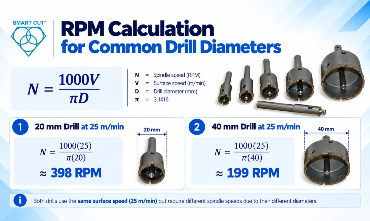
Once a surface speed has been selected for a controlled trial, it can be converted into spindle RPM using:
N = 1000V / πD
The following chart contains calculated values based on the illustrative surface speeds shown in the table above. These are mathematical examples, not recommended production settings.
|
Illustrative surface speed |
10 mm drill |
20 mm drill |
30 mm drill |
40 mm drill |
50 mm drill |
|---|---|---|---|---|---|
|
10 m/min |
318 RPM |
159 RPM |
106 RPM |
80 RPM |
64 RPM |
|
15 m/min |
477 RPM |
239 RPM |
159 RPM |
119 RPM |
95 RPM |
|
20 m/min |
637 RPM |
318 RPM |
212 RPM |
159 RPM |
127 RPM |
|
25 m/min |
796 RPM |
398 RPM |
265 RPM |
199 RPM |
159 RPM |
|
30 m/min |
955 RPM |
477 RPM |
318 RPM |
239 RPM |
191 RPM |
|
40 m/min |
1,273 RPM |
637 RPM |
424 RPM |
318 RPM |
255 RPM |
Consider a 20 mm core drill being evaluated at an illustrative surface speed of 25 m/min. The calculated spindle speed is approximately 398 RPM.
A 40 mm core drill operating at the same 25 m/min requires approximately 199 RPM.
The two drills therefore have different spindle settings but the same calculated peripheral speed.
For process documentation, record the actual RPM, measured drill diameter, and calculated surface speed. This allows results from different drill sizes and machines to be compared using the same engineering basis.
Why Engineers Reconsider Core Drill Speed
Speed changes normally occur after a measurable process condition changes. The first step should be identifying the failure mechanism rather than assuming that RPM is the cause. UKAM’s Diamond Core Drill & Drill Trouble Shooting Guide lists common symptoms, causes, and solutions.
|
Production observation |
Possible mechanism |
Investigation priority |
|---|---|---|
|
Penetration rate decreases |
Diamond wear or loading |
Inspect abrasive layer |
|
Entry chipping increases |
Excessive mechanical loading |
Check feed and runout |
|
Exit breakout increases |
High breakthrough load |
Check final feed stage |
|
Cutting temperature increases |
Excessive cutting energy or poor cooling |
Check speed and coolant |
|
Hole diameter changes |
Tool wear or runout |
Inspect drill and spindle |
|
Hole becomes tapered |
Deflection or uneven wear |
Check rigidity |
|
Cutting becomes intermittent |
Poor abrasive exposure |
Review bond condition |
|
Tool life varies significantly |
Changing workpiece or process conditions |
Review baseline |
A reduction in penetration does not automatically indicate that the spindle speed is too low. A worn abrasive surface, inappropriate bond, insufficient coolant, excessive feed, or spindle runout can produce similar symptoms.
For that reason, a controlled troubleshooting sequence should begin with tool condition and machine condition before major changes are made to spindle speed.
Baseline Documentation Before Changing the Process
A production trial should begin with a complete record of the existing condition.
|
Parameter |
Record |
Engineering purpose |
|---|---|---|
|
Material |
Exact grade and condition |
Establishes material response |
|
Thickness |
Actual workpiece thickness |
Defines breakthrough condition |
|
Drill OD |
Measured diameter |
Required for surface speed |
|
Drill ID |
Measured diameter |
Defines annular cutting area |
|
Mesh or micron specification |
Influences cutting action |
|
|
Bond type and specification |
Controls abrasive retention |
|
|
Supplier specification |
Defines abrasive loading |
|
|
Spindle speed |
Actual RPM |
Defines rotational condition |
|
Surface speed |
Calculated m/min |
Enables tool comparison |
|
Feed rate |
mm/min |
Defines mechanical loading |
|
Feed per revolution |
mm/rev |
Enables machine to machine comparison |
|
Coolant |
Type and concentration |
Controls heat and debris |
|
Coolant flow |
Measured flow |
Confirms delivery |
|
Runout |
Measured tool and spindle condition |
Affects hole geometry |
|
Hole diameter |
Actual measurement |
Defines dimensional result |
|
Entry damage |
Measured or classified |
Identifies entry fracture |
|
Exit damage |
Measured or classified |
Identifies breakthrough fracture |
|
Tool life |
Holes or linear cutting distance |
Defines useful life |
|
Scrap |
Percentage and failure reason |
Connects process to production cost |
Microscope images should be retained when edge integrity is critical. Dimensional inspection alone cannot identify every form of subsurface damage.
Cost Per Acceptable Part
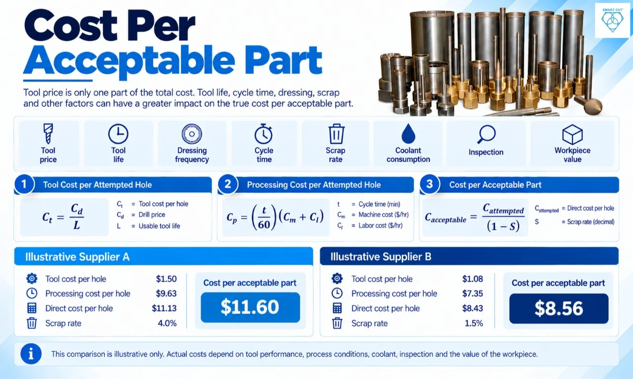
Tool price does not represent the complete cost of a diamond core drilling operation.
Tool life, cycle time, dressing frequency, scrap, coolant consumption, inspection, and workpiece value can have a greater effect on production economics than the purchase price of the drill. UKAM explains the wider concept in Understanding & Calculating Return on Investment for Diamond Core Drills & Other Tools.
The following comparison is illustrative only. It does not represent actual UKAM pricing, measured UKAM tool life, supplier performance, or customer production data.
|
Metric |
Illustrative Supplier A |
Illustrative Supplier B |
|---|---|---|
|
Drill price |
$180 |
$260 |
|
Usable tool life |
120 holes |
240 holes |
|
Dressing interval |
40 holes |
80 holes |
|
Cycle time |
5.5 min |
4.2 min |
|
Scrap rate |
4.0% |
1.5% |
|
Machine cost |
$60/hr |
$60/hr |
|
Labor cost |
$45/hr |
$45/hr |
|
Tool cost per attempted hole |
$1.50 |
$1.08 |
|
Machine and labor per attempted hole |
$9.63 |
$7.35 |
|
Direct cost per attempted hole |
$11.13 |
$8.43 |
|
Approximate cost per acceptable hole |
$11.60 |
$8.56 |
Tool cost per attempted hole is:
Ct = Cd / L
where Cd is drill cost and L is usable hole life.
For the first illustrative supplier:
Ct = 180 / 120 = $1.50
Processing cost is:
Cp = (t / 60)(Cm + Cl)
where t is cycle time in minutes, Cm is machine cost per hour, and Cl is labor cost per hour.
For a 5.5 minute cycle:
Cp = (5.5 / 60)(60 + 45) = $9.63
The cost of producing an acceptable part can then be approximated as:
Cacceptable = Cattempted / (1 − S)
where S is the scrap rate expressed as a decimal.
Using the illustrative Supplier A figures:
Cacceptable = 11.13 / (1 − 0.04) ≈ $11.60
This calculation demonstrates why tool purchase price should not be evaluated separately from tool life and process yield.
For high value sapphire, optical glass, quartz, and semiconductor components, the workpiece value should also be included in the economic model.
Selecting Diamond Grit, Bond, and Concentration
Core drilling performance depends on the relationship between diamond abrasive and bond behavior. UKAM’s Diamond Tool Bond Hardness & Wear Resistance article explains how the bond matrix retains and releases diamonds.
Diamond grit affects cutting point size and cutting action. Bond behavior determines how long individual diamond particles remain active before being released.
|
Material |
Grit consideration |
Bond consideration |
Primary risk |
|---|---|---|---|
|
Alumina |
Fine to medium depending on quality requirement |
Controlled abrasive exposure |
Edge chipping |
|
Silicon nitride |
Application specific |
Stable cutting action |
Thermal damage |
|
Silicon carbide |
Application specific |
Strong wear resistance |
Diamond wear |
|
Sapphire |
Fine grit where edge quality dominates |
Controlled abrasive release |
Edge fracture |
|
Fused silica |
Fine controlled cutting action |
Stable exposure |
Radial cracking |
|
Borosilicate glass |
Fine grit for edge control |
Controlled release |
Exit breakout |
|
Quartz |
Fine to medium depending on application |
Balanced retention and exposure |
Crystal fracture |
|
GaAs |
Fine abrasive condition |
Controlled mechanical loading |
Microcracking |
A bond that holds diamond too strongly can retain worn particles and reduce cutting efficiency. A bond that releases abrasive too quickly can shorten useful tool life.
The correct specification therefore depends on the required balance between penetration rate, hole quality, abrasive retention, and production life. Sintered constructions such as the 115DE SMART CUT® Series and multi layered electroplated options such as the 105DE SMART CUT® Series represent different bond approaches.
Step By Step Core Drilling Qualification
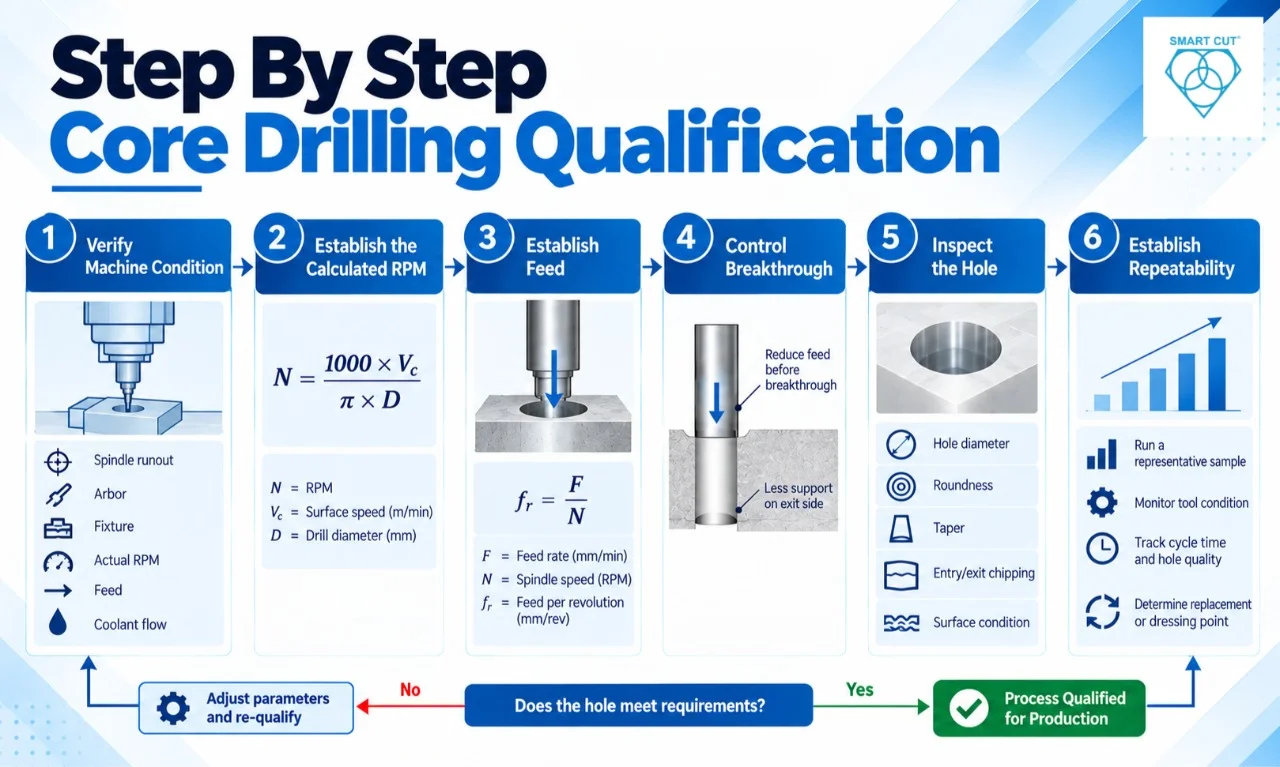
Phase 1: Verify Machine Condition
Begin with the machine before evaluating the tool.
|
Machine check |
What to verify |
|---|---|
|
Spindle runout |
Actual measured radial runout |
|
Arbor |
Clean seating surface and no damage |
|
Fixture |
No workpiece movement |
|
Spindle |
Actual RPM matches programmed value |
|
Feed |
Consistent movement |
|
Coolant |
Adequate flow into cutting zone |
Spindle runout is especially significant with small diameter drills because a small radial error can create uneven loading around the circumference. See UKAM’s guidance on material holding methods for fixturing considerations.
Phase 2: Establish the Calculated RPM
Select the trial surface speed and calculate RPM from drill diameter.
For a 25 mm drill at an illustrative 20 m/min:
N = 1000(20) / π(25)
N ≈ 255 RPM
The calculated value should then be checked against the tooling specification and machine capability.
Phase 3: Establish Feed
Feed should initially be varied independently from spindle speed.
Feed per revolution is:
fr = F / N
For a trial using 50 mm/min at 500 RPM:
fr = 50 / 500 = 0.10 mm/rev
If the same feed per revolution is required at 300 RPM:
F = frN
F = 0.10(300) = 30 mm/min
This calculation is useful when transferring a qualified process between machines.
Phase 4: Control Breakthrough
The final portion of drilling should be treated as a separate condition.
As the drill approaches the opposite surface, the remaining material provides less support. Fracture can therefore become more severe even when the main drilling parameters remain unchanged.
Feed reduction before breakthrough should be evaluated when exit chipping is the primary defect. UKAM’s Diamond Core Drills: Best Practices for Speed, Accuracy, and Tool Life also discusses breakthrough techniques and core hang-up.
Phase 5: Inspect the Hole
Measure:
- Hole diameter
- Roundness
- Taper
- Entry chip size
- Exit chip size
- Radial cracking
- Subsurface damage where required
- Surface condition
- Tool wear
Phase 6: Establish Repeatability
A single acceptable hole does not qualify a production process.
Run a representative sample and monitor the relationship between tool condition, penetration rate, cycle time, and hole quality.
The qualification should identify both the initial operating window and the point at which tool replacement or dressing becomes necessary.
Material Specific Drilling Conditions and Failure Modes
Alumina Ceramic
Alumina is used for electrical insulation, wear components, seals, fixtures, and other engineered ceramic applications.
Failure mode to watch: edge chipping with radial crack formation.
High feed during breakthrough can produce chips extending beyond the intended hole boundary. Spindle runout can increase localized loading and produce asymmetric damage.
|
Parameter |
Qualification focus |
|---|---|
|
Surface speed |
Stable cutting response |
|
Feed |
Controlled mechanical loading |
|
Grit |
Balance productivity and edge quality |
|
Coolant |
Stable cutting zone |
|
Inspection |
Entry and exit damage |
Silicon Nitride
Silicon nitride has high hardness and strong thermal characteristics.
Failure mode to watch: thermal cracking with localized edge fracture.
Monitor penetration rate and coolant delivery during extended drilling. Increasing cutting resistance can indicate abrasive wear or changing tool condition rather than insufficient spindle speed.
Silicon Carbide
Silicon carbide is highly abrasive and can produce rapid wear of the cutting system.
Failure mode to watch: accelerated diamond wear with declining penetration rate.
Tool life should be defined by useful production output. A drill that still produces holes but requires significantly longer cycle times may already have reached its economic replacement point.
Sapphire
Sapphire is single crystal aluminum oxide and is highly sensitive to localized fracture.
Failure mode to watch: edge breakout and subsurface cracking.
Where edge quality is critical, abrasive specification and feed control require close qualification. Breakthrough should be evaluated separately because the reduction in supporting material changes fracture behavior. For very small holes, see the SMART CUT® Micro & Miniature Diamond Core Drills.
Fused Silica
Fused silica is amorphous silicon dioxide and has different fracture behavior from crystalline quartz.
Failure mode to watch: radial cracking from the hole edge.
Stable coolant and controlled mechanical loading are required. A hole can meet dimensional requirements while still developing unacceptable crack propagation.
Quartz
Quartz is crystalline silicon dioxide and can exhibit directional fracture.
Failure mode to watch: crystal fracture and edge chipping.
Monitor tool condition against penetration rate and hole quality. Abrasive wear can increase cutting resistance before major dimensional changes become visible.
Borosilicate Glass
Borosilicate glass has good thermal resistance compared with many conventional glasses, but it remains susceptible to brittle fracture during drilling.
Failure mode to watch: exit breakout.
The breakthrough stage should be evaluated independently. Feed reduction near the exit can significantly affect the final edge condition.
Gallium Arsenide
GaAs is used in semiconductor and high frequency electronic applications where edge condition can affect subsequent processing.
Failure mode to watch: edge microcracking and localized breakout.
Mechanical loading should remain controlled. Magnified inspection should be used when small cracks can affect subsequent processing steps. Where a design needs geometry beyond a standard drill, custom diamond & CBN tools can be specified.
Supplier Evaluation
Supplier data becomes useful when the test conditions are clearly documented. UKAM’s article on Understanding Tradeoffs – Searching for Perfect Diamond Drill & Tool is a helpful reference.
|
What to ask |
What the answer reveals |
|---|---|
|
What surface speed was used? |
Basis of the speed recommendation |
|
What drill diameter was tested? |
Whether RPM data transfers correctly |
|
What material grade was tested? |
Relevance of the result |
|
What diamond grit was used? |
Expected cutting behavior |
|
What bond was used? |
Abrasive retention characteristics |
|
What concentration was used? |
Diamond loading |
|
What feed rate was used? |
Mechanical loading |
|
What coolant flow was used? |
Heat and debris control |
|
How was tool life defined? |
Comparability of tool life claims |
|
What hole quality was achieved? |
Relationship between life and quality |
|
What dressing method was used? |
Maintenance requirement |
|
What failure mode ended the test? |
Supplier process knowledge |
Supplier comparisons should use equivalent conditions wherever practical. A tool life value from one material grade or machine should not automatically be transferred to another application.
UKAM SMART CUT Technology Comparison
SMART CUT tooling should be evaluated using the same measurable engineering criteria applied to any diamond core drilling process. To understand the underlying design, read What is SMART CUT Technology or visit the SMART CUT® technology page. The correct configuration depends on the material, hole geometry, tool dimensions, machine capability, coolant system, production volume, and quality requirement.
|
Engineering factor |
Conventional selection approach |
SMART CUT application evaluation |
|---|---|---|
|
Material |
General material category |
Specific material and grade |
|
Drill diameter |
Catalog size selection |
Application matched diameter |
|
Diamond grit |
General grit selection |
Matched to material and quality requirement |
|
Bond |
General bond selection |
Evaluate abrasive retention and cutting response |
|
Surface speed |
RPM often used independently |
Calculate surface speed from actual diameter |
|
Feed |
General machine setting |
Qualify against penetration and hole quality |
|
Coolant |
General application recommendation |
Match delivery to the cutting zone |
|
Hole quality |
Diameter and visual inspection |
Define dimensional and edge criteria |
|
Tool life |
Number of holes |
Measure usable life based on quality and productivity |
|
Dressing |
Fixed or operator determined |
Evaluate against tool condition and cutting response |
|
Supplier economics |
Tool purchase price |
Cost per acceptable part |
|
Process transfer |
Copy RPM and feed values |
Transfer surface speed and feed per revolution |
This comparison does not establish a universal SMART CUT operating condition. The same qualification methodology should be applied to the selected tool and production application. Browse the full range of UKAM diamond core drills, including the 100DE and 120DE thin wall series, or the non-coring bottoming drills.
Qualification Checklist
Machine Condition
|
Qualification item |
Status |
|---|---|
|
Spindle runout measured |
☐ |
|
Arbor inspected |
☐ |
|
Fixture rigidity verified |
☐ |
|
Actual RPM verified |
☐ |
|
Feed system verified |
☐ |
|
Coolant flow verified |
☐ |
Tool Specification
|
Qualification item |
Status |
|---|---|
|
Drill OD measured |
☐ |
|
Drill ID measured |
☐ |
|
Diamond grit documented |
☐ |
|
Bond documented |
☐ |
|
Diamond concentration documented |
☐ |
|
Initial tool condition recorded |
☐ |
Process Parameters
|
Qualification item |
Status |
|---|---|
|
Surface speed calculated |
☐ |
|
Actual RPM recorded |
☐ |
|
Feed rate recorded |
☐ |
|
Feed per revolution calculated |
☐ |
|
Coolant type recorded |
☐ |
|
Coolant flow recorded |
☐ |
|
Breakthrough condition defined |
☐ |
Quality and Economics
|
Qualification item |
Status |
|---|---|
|
Hole diameter measured |
☐ |
|
Roundness checked |
☐ |
|
Entry chipping measured |
☐ |
|
Exit chipping measured |
☐ |
|
Cracks inspected |
☐ |
|
Surface condition evaluated |
☐ |
|
Tool wear documented |
☐ |
|
Dressing frequency recorded |
☐ |
|
Cycle time recorded |
☐ |
|
Scrap rate recorded |
☐ |
|
Cost per acceptable part calculated |
☐ |
Common Engineering Mistakes
|
Mistake |
Production consequence |
|---|---|
|
Using the same RPM for different drill diameters |
Surface speed changes with diameter |
|
Increasing RPM whenever penetration decreases |
Heat can increase without correcting abrasive wear |
|
Changing speed and feed together |
Trial results become difficult to interpret |
|
Ignoring coolant flow |
Cutting temperature and debris conditions become unstable |
|
Measuring only the first few holes |
Long term tool behavior remains unknown |
|
Inspecting only hole diameter |
Cracks and edge damage can remain undetected |
|
Ignoring breakthrough |
Exit damage can dominate scrap |
|
Comparing supplier purchase price only |
Total production cost remains hidden |
|
Ignoring spindle runout |
Cutting load becomes uneven |
|
Applying data from another material grade |
Process transfer can fail |
|
Treating illustrative values as production recommendations |
Unverified parameters can be applied incorrectly |
The last mistake is particularly relevant when using published speed charts. A calculated value demonstrates a relationship between RPM and surface speed. It does not establish that the selected surface speed is suitable for every drill, machine, material grade, or production requirement.
Engineering Calculations Used During Process Development
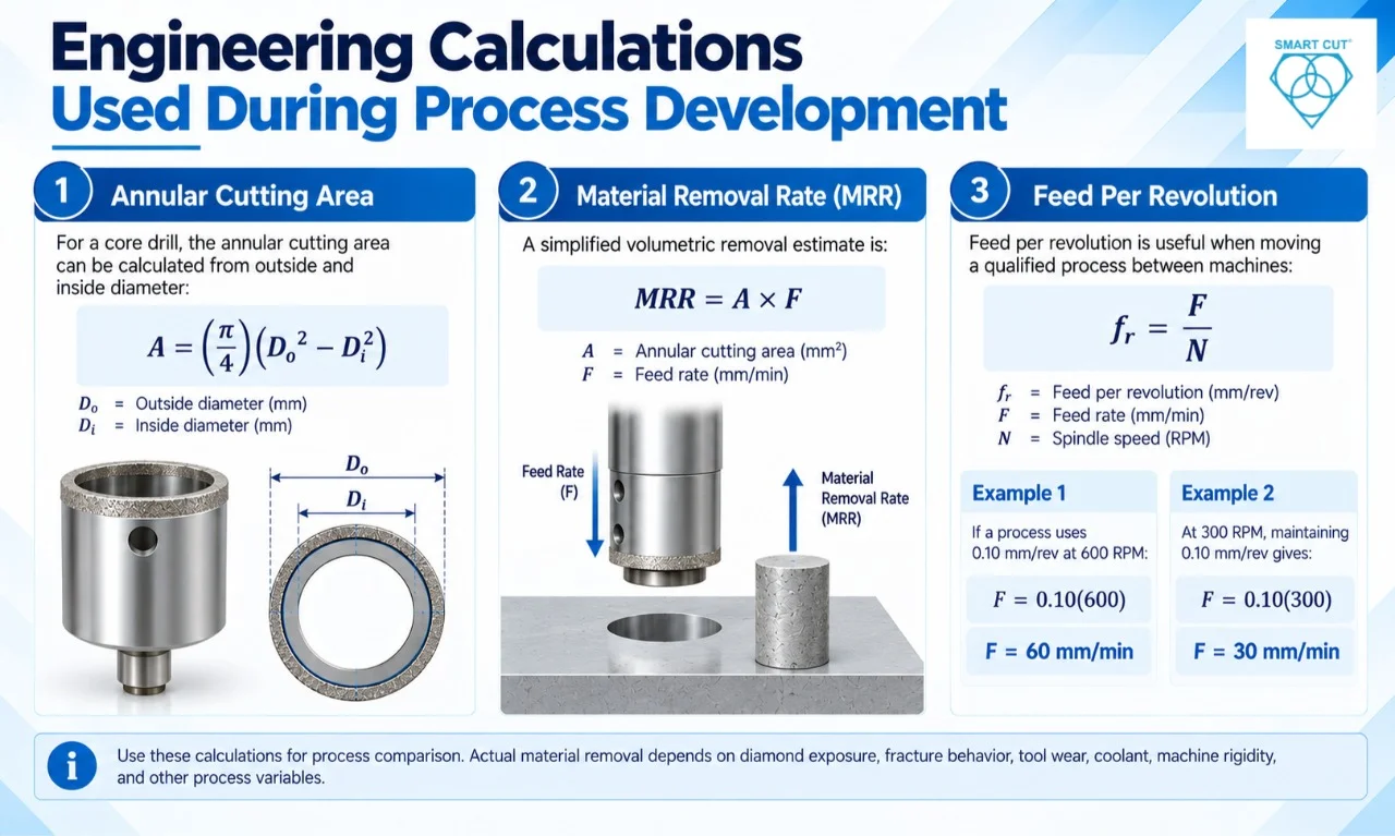
For a core drill, the annular cutting area can be calculated from outside and inside diameter:
A = (π/4)(Do2 − Di2)
where Do is outside diameter and Di is inside diameter.
A simplified volumetric removal estimate is:
MRR = A × F
where F is feed rate in mm/min.
This provides a useful method for comparing different core drill geometries and feed conditions. Actual material removal depends on diamond exposure, fracture behavior, tool wear, coolant, machine rigidity, and other process variables.
The calculation should therefore be treated as a comparison tool rather than a direct prediction of production performance.
Feed per revolution is also useful when moving a qualified process between machines:
fr = F / N
If a process uses 0.10 mm/rev at 600 RPM, the corresponding feed is:
F = 0.10(600) = 60 mm/min
At 300 RPM, maintaining 0.10 mm/rev gives:
F = 0.10(300) = 30 mm/min
This allows the cutting load associated with feed to be compared independently of spindle RPM.
Frequently Asked Questions
Surface speed accounts for drill diameter and provides a common basis for comparing tools. A 10 mm drill at 500 RPM operates at approximately 15.7 m/min, while a 50 mm drill at the same RPM operates at approximately 78.5 m/min. Recording only RPM can therefore hide a substantial difference in cutting speed.
Chipping results from localized fracture around the cutting zone. Feed, breakthrough loading, spindle runout, fixture rigidity, abrasive condition, and tool geometry can all contribute. The location and pattern of the damage should be evaluated before changing spindle speed. Entry and exit damage should be treated as separate observations.
There is no single speed that applies to every glass drilling application. Glass composition, thickness, drill diameter, diamond specification, coolant, feed, and required edge quality all affect the process. Any numerical speed used during development should be treated as a trial value until it has been qualified on the actual production setup.
Sapphire is a single crystal aluminum oxide, while engineering alumina is generally polycrystalline. Their fracture behavior is therefore different. Sapphire qualification should specifically evaluate edge breakout, crystal fracture, and subsurface cracking rather than assuming that alumina drilling conditions transfer directly.
Both materials are silicon dioxide, but quartz is crystalline while fused silica is amorphous. Quartz can exhibit crystal related fracture behavior, while fused silica can develop radial cracking around the hole. The two materials should therefore have separate qualification records.
Not automatically. Tool wear, glazing, bond behavior, coolant deficiency, runout, and material loading can all reduce penetration. Increasing RPM without identifying the cause can increase cutting temperature without restoring the required cutting action. Inspect the tool and compare its condition with the original process baseline. A water swivel adapter and dressing sticks are common accessories for restoring stable cutting.
Breakthrough should be treated as a separate portion of the drilling cycle. As the drill approaches the opposite surface, the remaining material provides less support and fracture can occur more readily. Feed reduction before breakthrough should be evaluated when exit chipping or breakout controls the quality result.
Compare suppliers using equivalent material, drill diameter, speed, feed, coolant, inspection criteria, and tool life definitions. Record purchase price, usable tool life, dressing frequency, cycle time, scrap rate, and hole quality. Cost per acceptable part provides a more useful production metric than purchase price alone. For more, request an application review through UKAM’s consultation form.
Summary: Core Engineering Principles
- Use surface speed as the common basis for comparing diamond core drilling conditions.
- Calculate RPM from actual drill diameter instead of transferring RPM directly between different drill sizes.
- Record RPM and surface speed together in the process documentation.
- Treat speed, feed, diamond grit, bond, coolant, runout, fixturing, and breakthrough as connected process variables.
- Establish a measured baseline before changing a production parameter.
- Change major variables independently during qualification so their effects can be identified.
- Treat breakthrough as a separate machining condition.
- Identify the specific failure mode associated with each material.
- Evaluate tool life using useful production output and acceptable hole quality.
- Compare suppliers using cost per acceptable part rather than drill purchase price alone.
- Include scrap, dressing, cycle time, and workpiece value when they materially affect production economics.
- Use feed per revolution when transferring a process between machines.
- Use mathematical calculations to establish trial conditions, not to claim unverified production performance.
- Clearly distinguish illustrative values from verified tooling specifications and measured production data.
- Establish final operating parameters from the actual material, drill, machine, coolant system, geometry, and quality requirement.
Trusted by Tens of Thousands of Manufacturers, Laboratories,
Research Institutions Worldwide Since 1990
American Based Manufacturer
Established in 1990
