








































Precision Diamond Saw SOP: A Practical Template for Materials and Research Laboratories

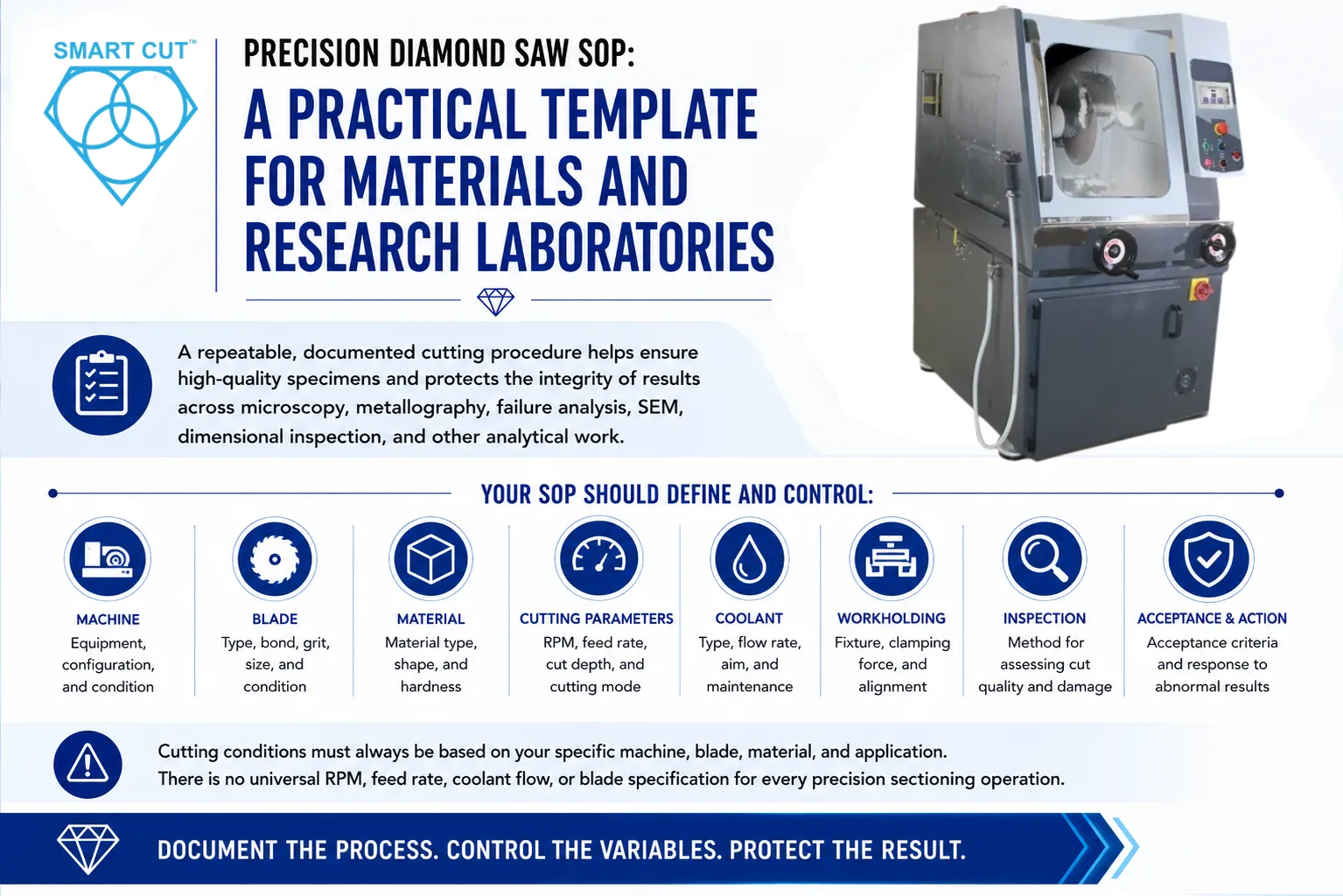
Table of Contents
TogglePrecision diamond sawing is often treated as a straightforward sample-preparation operation: select a blade, mount the specimen, make the cut, and continue to grinding or polishing.
For materials and research laboratories, that approach is often too simplistic.
The sectioning operation can influence the condition of the specimen before microscopy, metallography, failure analysis, SEM examination, dimensional inspection, or other analytical work begins. Excessive cutting force, blade deflection, vibration, heat, poor workholding, or an unsuitable blade can introduce damage that becomes part of the specimen rather than part of the original material.
A laboratory therefore needs more than operating instructions. It needs a repeatable, documented cutting procedure that defines the machine, blade, material, cutting parameters, coolant, workholding, inspection method, acceptance criteria, and response to abnormal results.
This article provides a practical framework for developing and using that procedure. It also provides an SOP structure that laboratories can adapt to their specific machine and material requirements.
The numerical cutting conditions in an SOP should always be tied to the specific machine, blade, material, and application. There is no universal RPM, feed rate, coolant flow, or blade specification that should be applied to every precision sectioning operation.
Trusted by Tens of Thousands of Manufacturers, Laboratories Research Institutions Worldwide Since 1990

American Based Manufacturer

Established in 1990


Custom manufacturing


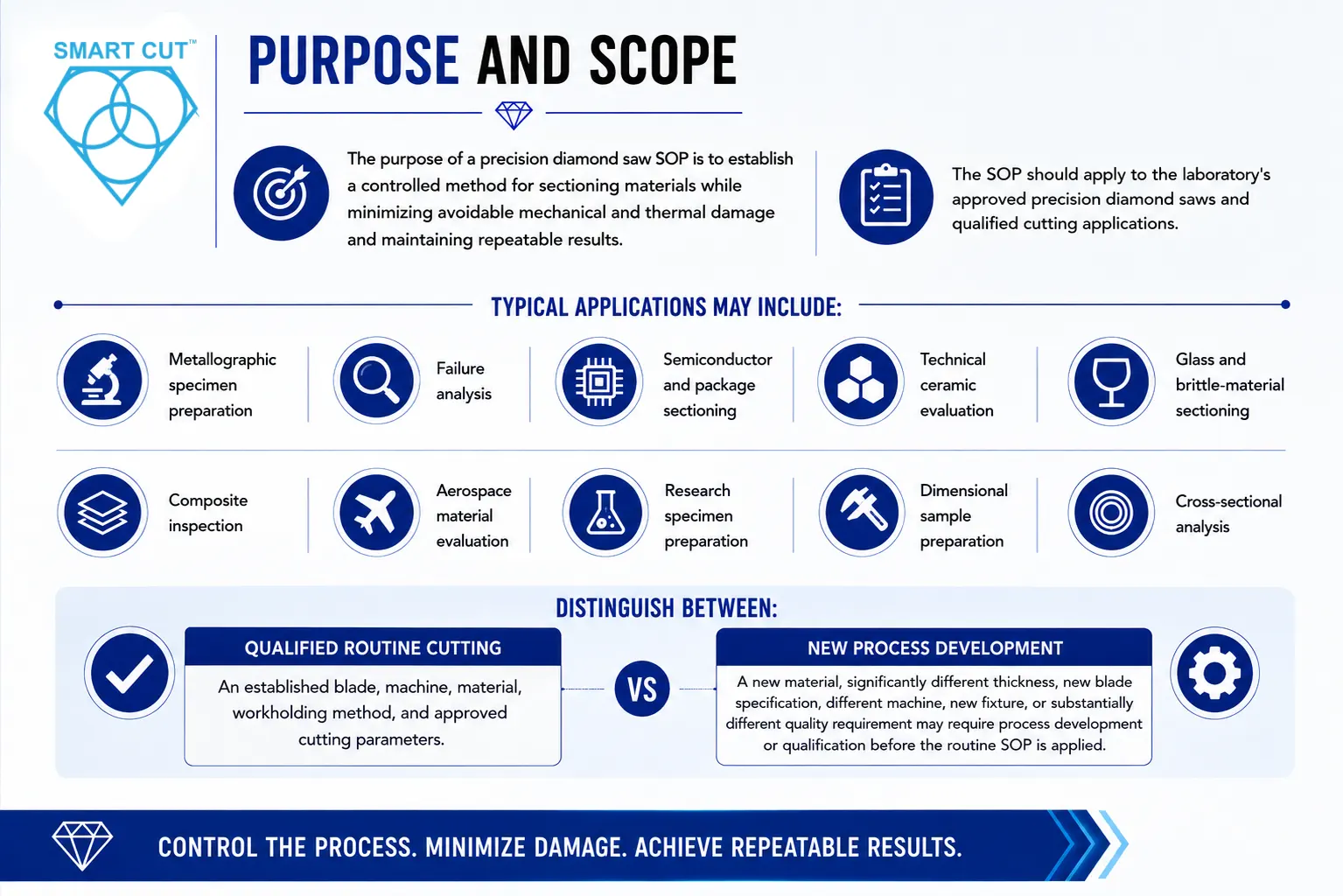
The purpose of a precision diamond saw SOP is to establish a controlled method for sectioning materials while minimizing avoidable mechanical and thermal damage and maintaining repeatable results.
The SOP should apply to the laboratory’s approved precision diamond saws and qualified cutting applications.
Depending on the laboratory, applications may include:
- Metallographic specimen preparation
- Failure analysis
- Semiconductor and package sectioning
- Technical ceramic evaluation
- Glass and brittle-material sectioning
- Composite inspection
- Aerospace material evaluation
- Research specimen preparation
- Dimensional sample preparation
- Cross-sectional analysis
The SOP should distinguish between qualified routine cutting and new process development.
A qualified routine process uses an established blade, machine, material, workholding method, and approved cutting parameters.
A new material, significantly different thickness, new blade specification, different machine, new fixture, or substantially different quality requirement may require process development or qualification before the routine SOP is applied.
The first page of the laboratory SOP should make the document itself traceable.
A practical document-control section should include:
| Field | Laboratory Record |
|---|---|
| SOP Title | Precision Diamond Saw Operating Procedure |
| SOP Number | __________________ |
| Revision | __________________ |
| Effective Date | __________________ |
| Department / Laboratory | __________________ |
| Machine ID | __________________ |
| Prepared By | __________________ |
| Reviewed By | __________________ |
| Approved By | __________________ |
| Approval Date | __________________ |
| Supersedes | __________________ |
The revision history should also be maintained.
| Revision | Date | Description of Change | Author | Approval |
|---|---|---|---|---|
| ____ | ____ | __________________ | ____ | ____ |
| ____ | ____ | __________________ | ____ | ____ |
| ____ | ____ | __________________ | ____ | ____ |
This is particularly important when cutting conditions are changed after process-development work. Operators should be able to determine which version of the procedure was used to produce a particular specimen.
Equipment, Blade, and Material Identification
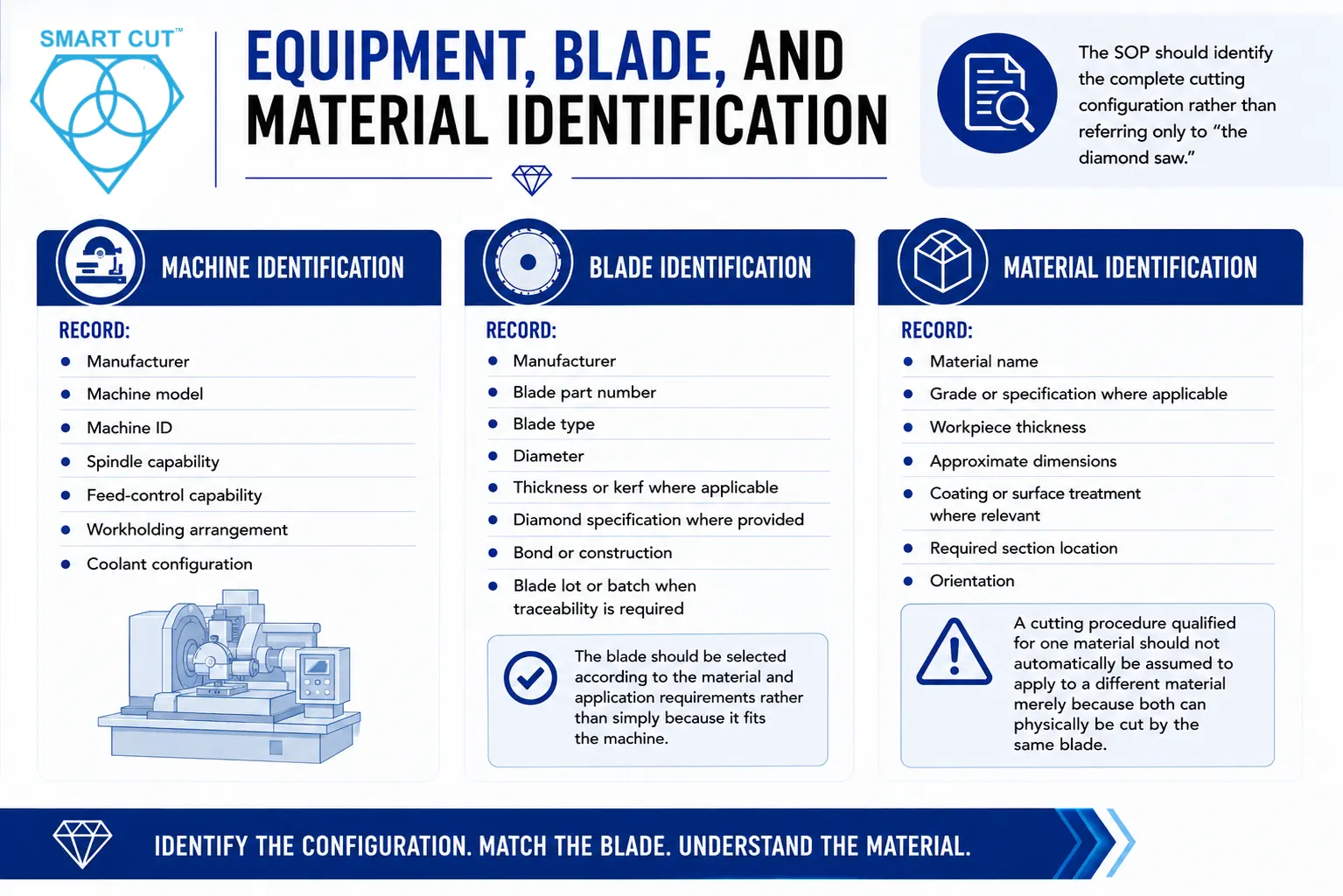
The SOP should identify the complete cutting configuration rather than referring only to “the diamond saw.”
Machine Identification
Record:
- Manufacturer
- Machine model
- Machine ID
- Spindle capability
- Feed-control capability
- Workholding arrangement
- Coolant configuration
Blade Identification
Record:
- Manufacturer
- Blade part number
- Blade type
- Diameter
- Thickness or kerf where applicable
- Diamond specification where provided
- Bond or construction
- Blade lot or batch when traceability is required
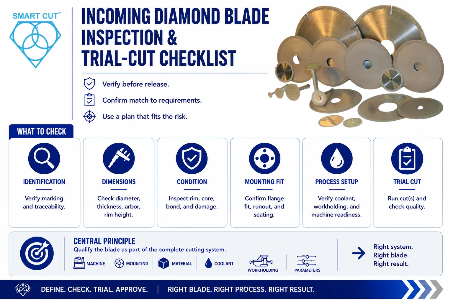
The blade should be selected according to the material and application requirements rather than simply because it fits the machine.
Material Identification
The SOP record should identify:
- Material name
- Grade or specification where applicable
- Workpiece thickness
- Approximate dimensions
- Coating or surface treatment where relevant
- Required section location
- Orientation
A cutting procedure qualified for one material should not automatically be assumed to apply to a different material merely because both can physically be cut by the same blade.
Safety and Pre-Operation Requirements
Safety requirements should be completed before precision cutting begins.
The laboratory’s machine-specific safety procedure and applicable regulations should take precedence over any general guidance in this article.
Before operation, verify:
- Required machine guarding is in place
- The blade enclosure or guard is correctly positioned
- Emergency-stop functionality is available according to the machine procedure
- Workholding components are secure
- The blade is correctly mounted
- The cutting area is clear
- Coolant is available and correctly configured
- Required PPE is being used
- The operator is authorized and trained to use the equipment
PPE requirements should be determined by the laboratory’s hazard assessment and machine documentation.
Depending on the operation, this may include appropriate eye or face protection, protective clothing, gloves for handling specimens where appropriate, hearing protection where required, and other site-specific controls.
Gloves should not be used in a manner that creates an entanglement hazard around rotating machinery. Handling procedures should distinguish between preparing or cleaning a stationary machine and working near moving components.
Operators should also understand the hazards associated with:
- Rotating blades
- Sharp specimens
- Cutting debris
- Coolant exposure
- Material-specific dust or particles
- Broken or fractured specimens
- Electrical equipment and coolant systems
The machine should not be operated if a known safety-critical condition has not been resolved.
Pre-Operation Machine Inspection
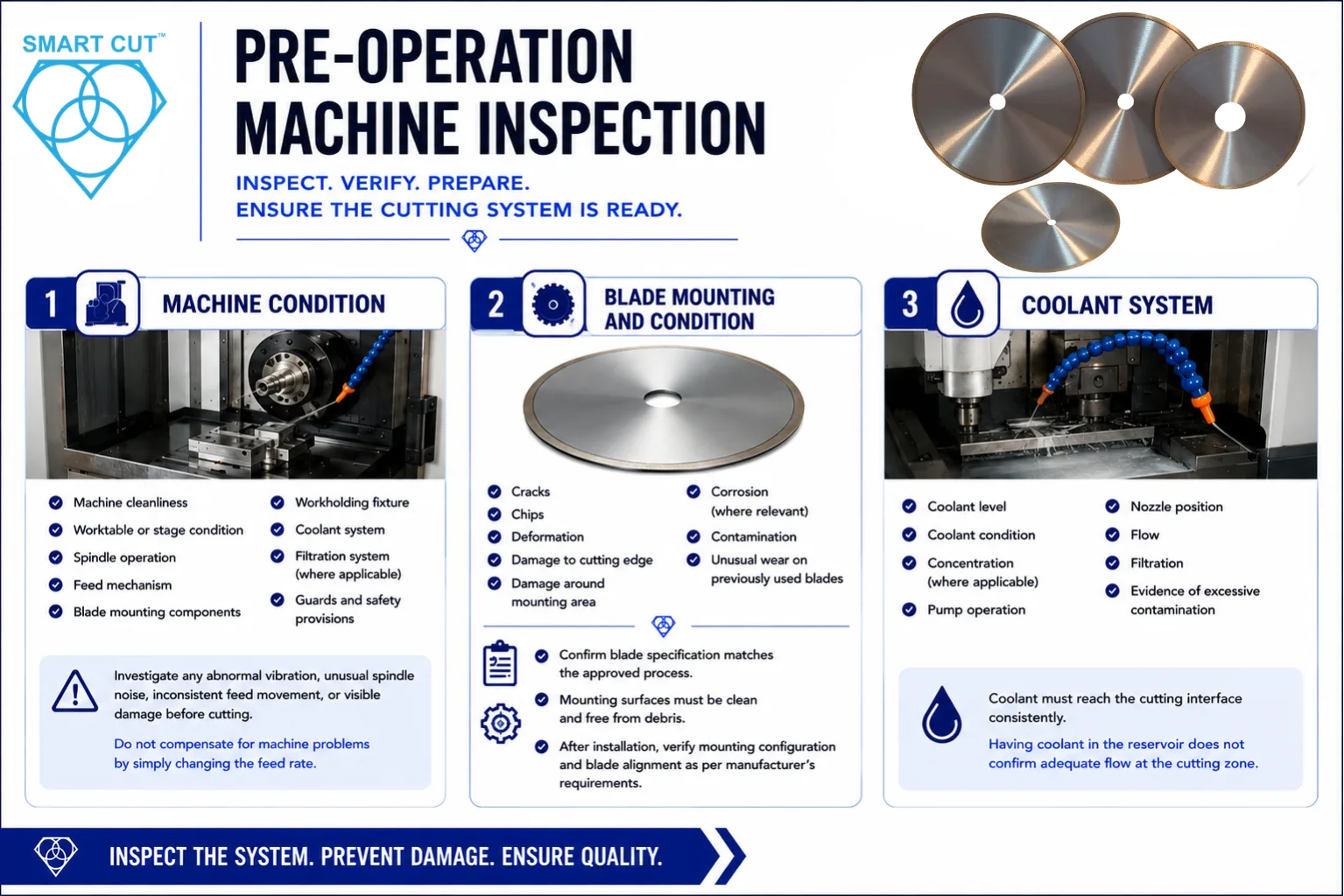
Before mounting the specimen, inspect the machine.
The purpose is to establish that the cutting system is in a suitable condition before the blade contacts the material.
Machine Condition
Check:
- Machine cleanliness
- Worktable or stage condition
- Spindle operation
- Feed mechanism
- Blade mounting components
- Workholding fixture
- Coolant system
- Filtration system where applicable
- Guards and safety provisions
Any abnormal vibration, unusual spindle noise, inconsistent feed movement, or visible damage should be investigated before precision samples are processed.
A machine problem should not be compensated for by simply changing the feed rate.
Blade Mounting and Condition
Inspect the blade before installation.
Check for:
- Cracks
- Chips
- Deformation
- Damage to the cutting edge
- Damage around the mounting area
- Corrosion where relevant
- Contamination
- Unusual wear on previously used blades
Confirm that the blade specification matches the approved process.
Mounting surfaces should be clean and free from debris that could prevent proper seating.
After installation, verify the mounting configuration and blade alignment according to the machine and blade manufacturer’s requirements.
Coolant System
Before cutting, inspect:
- Coolant level
- Coolant condition
- Concentration where applicable
- Pump operation
- Nozzle position
- Flow
- Filtration
- Evidence of excessive contamination
Coolant should be capable of reaching the cutting interface consistently.
Simply having coolant in the machine reservoir does not confirm that the cutting zone is receiving adequate coolant.
Workholding is one of the most important controls in precision sectioning.
The workpiece must remain stable during cutting without introducing unnecessary mechanical stress.
Before cutting, confirm:
- Correct specimen identification
- Correct cut location
- Correct orientation
- Adequate support
- Secure clamping
- Blade clearance
- Fixture clearance
- No interference with machine movement
For brittle specimens, clamping force should be sufficient to prevent movement but should not unnecessarily load the material.
Poor workholding can produce symptoms that appear to be blade problems, including:
- Edge chipping
- Cracking
- Kerf variation
- Blade wandering
- Dimensional error
The workholding method should therefore be included in the qualified process record.
Blade Selection Based on the Application
Blade selection should begin with the material and required result.
Important factors include:
- Material hardness
- Brittleness
- Material structure
- Thickness
- Geometry
- Required edge quality
- Required dimensional accuracy
- Thermal sensitivity
- Expected cutting load
- Machine capability
Different blade constructions can produce significantly different cutting behavior.
The SOP should therefore identify the approved blade specification for each qualified application.
Example Blade-Selection Record
| Application Factor | Required Information |
|---|---|
| Material | __________________ |
| Material Grade | __________________ |
| Thickness | __________________ |
| Workpiece Geometry | __________________ |
| Required Edge Quality | __________________ |
| Dimensional Requirement | __________________ |
| Thermal Sensitivity | __________________ |
| Machine | __________________ |
| Approved Blade | __________________ |
| Blade Specification | __________________ |
| Qualification Reference | __________________ |
This record creates a direct connection between the material requirement and the blade selected for the process.
Establishing Cutting Parameters
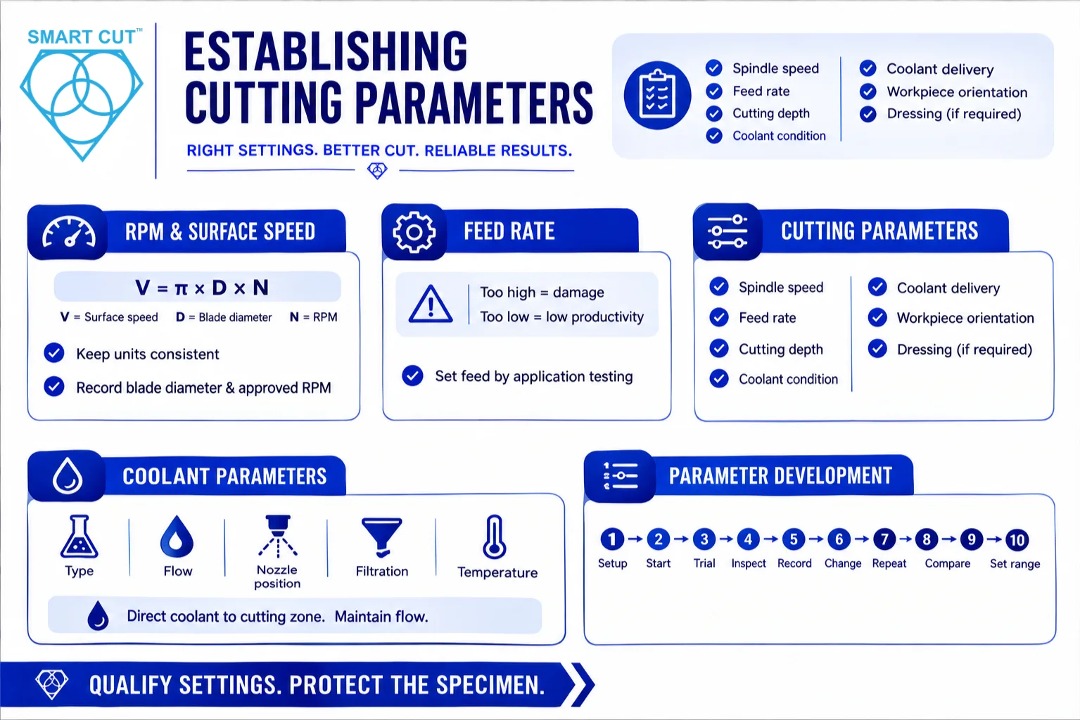
The primary cutting parameters should be documented before production or routine laboratory sectioning begins.
These normally include:
- Spindle speed
- Feed rate
- Cutting depth
- Number of passes where applicable
- Coolant condition
- Coolant delivery
- Workpiece orientation
- Any application-specific conditioning or dressing procedure
The values should come from qualified process data, manufacturer recommendations, or controlled application-development work.
They should not be treated as generic laboratory settings.
RPM and Surface Speed
For a given blade diameter, spindle RPM determines the approximate peripheral speed of the blade.
The relationship can be used when converting between an established surface-speed requirement and the corresponding spindle setting:
Surface speed = π × blade diameter × spindle speed
When using this relationship, units must be kept consistent.
For example, if blade diameter is expressed in meters and spindle speed in revolutions per minute, the resulting surface speed is expressed in meters per minute.
This relationship is useful when comparing blade operating conditions across machines with different spindle-speed capabilities.
The laboratory should record the actual blade diameter and approved spindle setting rather than relying on RPM alone when surface speed is an important process variable.
Feed Rate
Feed rate determines how quickly the blade advances through the material.
An excessively aggressive feed can increase:
- Cutting force
- Blade deflection
- Vibration
- Edge damage
- Subsurface damage
- Blade wear
An excessively conservative feed can reduce productivity without necessarily improving specimen quality.
The appropriate feed should therefore be established by application-specific testing.
For a new material or blade, a controlled parameter-development sequence is preferable to selecting a random operating point.
Recommended Parameter-Development Sequence
A practical development sequence is:
- Confirm the blade and machine configuration
- Start from manufacturer or previously qualified operating guidance
- Establish a conservative initial cutting condition
- Perform a controlled trial cut
- Inspect the specimen
- Record blade behavior and cutting stability
- Change one major process variable
- Repeat the trial
- Compare cut quality and productivity
- Establish the qualified operating window
This approach produces useful engineering data while avoiding the common problem of changing several variables simultaneously.
Coolant Parameters
Coolant requirements should be documented for the specific application.
Record, where applicable:
- Coolant type
- Concentration
- Flow
- Nozzle location
- Filtration
- Temperature requirements
- Replacement or maintenance requirements
Coolant should be directed into the cutting interface and maintained throughout the operation.
The SOP should avoid declaring a single coolant flow rate as universally correct because the required flow depends on machine configuration, blade size, material, cutting load, and coolant-delivery design.
Approved Cutting-Parameter Record
The following record can form part of the laboratory’s actual SOP package:
| Parameter | Approved Value | Actual Value | Operator Initials |
|---|---|---|---|
| Blade | __________ | __________ | ____ |
| Blade Diameter | __________ | __________ | ____ |
| Blade Thickness / Kerf | __________ | __________ | ____ |
| Spindle Speed | __________ | __________ | ____ |
| Surface Speed, if used | __________ | __________ | ____ |
| Feed Rate | __________ | __________ | ____ |
| Cutting Depth | __________ | __________ | ____ |
| Number of Passes | __________ | __________ | ____ |
| Coolant Type | __________ | __________ | ____ |
| Coolant Concentration | __________ | __________ | ____ |
| Coolant Flow | __________ | __________ | ____ |
| Workholding Method | __________ | __________ | ____ |
The distinction between approved value and actual value is important.
It allows the laboratory to determine whether a result was produced within the qualified process or whether an operator deviation occurred.
Pre-Cut Release Check
Before starting the cut, the operator should confirm that the complete setup is ready.
Pre-Cut Record
| Check | Status |
|---|---|
| Correct machine identified | ☐ |
| Correct blade identified | ☐ |
| Blade condition verified | ☐ |
| Blade correctly mounted | ☐ |
| Workpiece identified | ☐ |
| Workpiece correctly positioned | ☐ |
| Workholding secure | ☐ |
| Blade clearance verified | ☐ |
| Approved RPM confirmed | ☐ |
| Approved feed confirmed | ☐ |
| Cutting depth confirmed | ☐ |
| Coolant available | ☐ |
| Coolant delivery verified | ☐ |
| Required guarding confirmed | ☐ |
| Required PPE confirmed | ☐ |
| Measurement equipment available | ☐ |
This is not intended to replace the laboratory’s formal safety checklist. It is a process-control record that confirms the critical cutting conditions before the specimen is processed.
Once these controls are verified, the operator can proceed to the controlled cutting sequence and subsequent inspection.
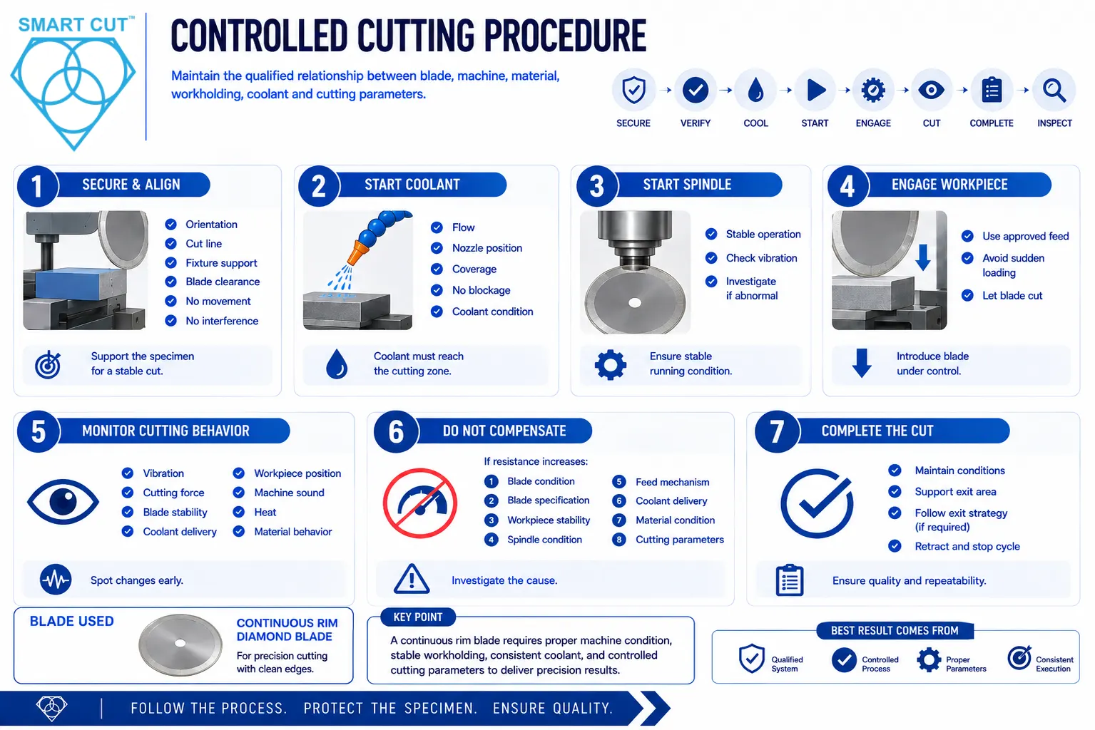
Once the pre-cut release checks are complete, the operator can begin the sectioning operation.
The objective is to maintain the qualified relationship between blade, machine, material, workholding, coolant, and cutting parameters throughout the cut.
The basic sequence is:
Secure → Verify → Cool → Start → Engage → Cut → Monitor → Complete → Inspect
The operator should not make undocumented process changes simply because the cut appears slower or faster than expected. Any significant deviation should be recorded and investigated according to the laboratory’s quality procedure.
Secure and Align the Workpiece
Confirm that the specimen is fully supported and that the intended cut line is aligned with the blade.
Before starting:
- Verify the specimen orientation.
- Confirm the cutting location.
- Confirm adequate fixture support.
- Check blade clearance.
- Verify that the specimen cannot shift during the cut.
- Confirm that the fixture will not interfere with blade travel.
For thin, brittle, or irregular specimens, support should be designed to minimize vibration and movement without applying unnecessary clamping force.
Start Coolant Before Blade Engagement
Coolant should reach the cutting interface before the blade enters the workpiece.
Verify:
- Consistent flow
- Correct nozzle position
- Adequate coverage
- No blockage
- Acceptable coolant condition
If coolant delivery is interrupted during a heat-sensitive operation, the operator should stop or interrupt the process according to the machine and laboratory procedure rather than continuing under uncontrolled conditions.
Start the Spindle and Establish Stable Operation
Start the spindle according to the machine’s operating procedure and allow the cutting system to reach the required operating condition.
Before engagement, observe the blade for abnormal vibration or movement.
Unexpected vibration at this stage should be investigated before the blade contacts the specimen.
Possible causes include:
- Incorrect mounting
- Contamination between mounting surfaces
- Blade damage
- Spindle runout
- Machine condition
Engage the Workpiece Under Controlled Feed
Introduce the blade into the specimen using the approved feed method.
Avoid sudden loading.
The initial engagement can be particularly important for brittle materials because excessive impact or cutting force can initiate edge damage before the main sectioning operation is established.
The operator should allow the blade to perform the cutting rather than forcing it through the material.
Monitor Cutting Behavior
During the cut, monitor the process for changes in:
- Vibration
- Cutting resistance
- Blade stability
- Coolant delivery
- Workpiece position
- Machine sound
- Visible heat
- Material behavior
A change in cutting behavior can indicate a change in blade condition, material characteristics, machine stability, or process conditions.
Operators should be trained to recognize the difference between normal process variation and an abnormal condition requiring intervention.
Do Not Compensate for Abnormal Cutting by Increasing Feed
If cutting resistance increases unexpectedly, increasing feed pressure can make the problem worse.
Instead, investigate the system.
Check:
- Blade condition
- Blade specification
- Workpiece stability
- Spindle condition
- Feed mechanism
- Coolant delivery
- Material condition
- Current cutting parameters
This approach prevents an underlying machine or blade problem from being converted into additional specimen damage.
Complete the Cut Under Controlled Conditions
Maintain the qualified cutting conditions through the final portion of the section.
For brittle materials, the exit portion of the cut can require particular attention because inadequate support may allow the remaining material to fracture or break away.
Where the application requires a specific exit strategy, that method should be documented in the qualified SOP.
After the blade clears the workpiece, follow the machine procedure for retracting the blade and stopping the cutting cycle.
Material-Specific Operating Considerations
The overall SOP can remain standardized, but the cutting strategy should account for material behavior.
A laboratory should not expect identical cutting conditions or acceptance criteria for ceramics, silicon, glass, composites, and metals.
Ceramics and Carbides
Technical ceramics and carbide materials can withstand substantial compressive loading while remaining highly susceptible to brittle fracture.
Important controls include:
- Appropriate diamond blade specification
- Stable workholding
- Controlled feed
- Adequate coolant
- Spindle stability
- Proper specimen support
The inspection should consider both visible edge damage and, where relevant, subsurface damage.
Glass and Brittle Materials
Glass and other brittle materials can be sensitive to both mechanical and thermal loading.
Potential problems include:
- Edge chipping
- Cracking
- Fracture propagation
- Localized breakage
- Thermal cracking
Workholding and cutting conditions should be selected to prevent uncontrolled fracture.
The specimen should also remain adequately supported as the blade approaches the end of the cut.
Silicon and Semiconductor Materials
Semiconductor materials and packages can require particularly controlled sectioning because cutting-induced damage may affect subsequent failure analysis.
Relevant characteristics may include:
- Edge chipping
- Subsurface cracking
- Cut location
- Dimensional accuracy
- Thermal effects
- Contamination
For these applications, acceptance criteria should be linked to the downstream analytical requirement rather than simply whether the specimen has been successfully separated.
Metals and Alloys
Metals can exhibit different cutting mechanisms depending on hardness, alloy composition, microstructure, and thermal behavior.
Potential problems include:
- Smearing
- Material loading
- Excessive heat
- Surface deformation
- Accelerated blade wear
For metallographic work, the sectioning process should minimize alteration of the structure that will subsequently be examined.
Composites
Composites may contain materials with substantially different cutting behavior within the same workpiece.
Potential problems include:
- Delamination
- Fiber pullout
- Matrix damage
- Edge breakout
- Localized heating
Blade selection, feed control, workholding, and support should therefore be considered together.
Cut-Quality Inspection
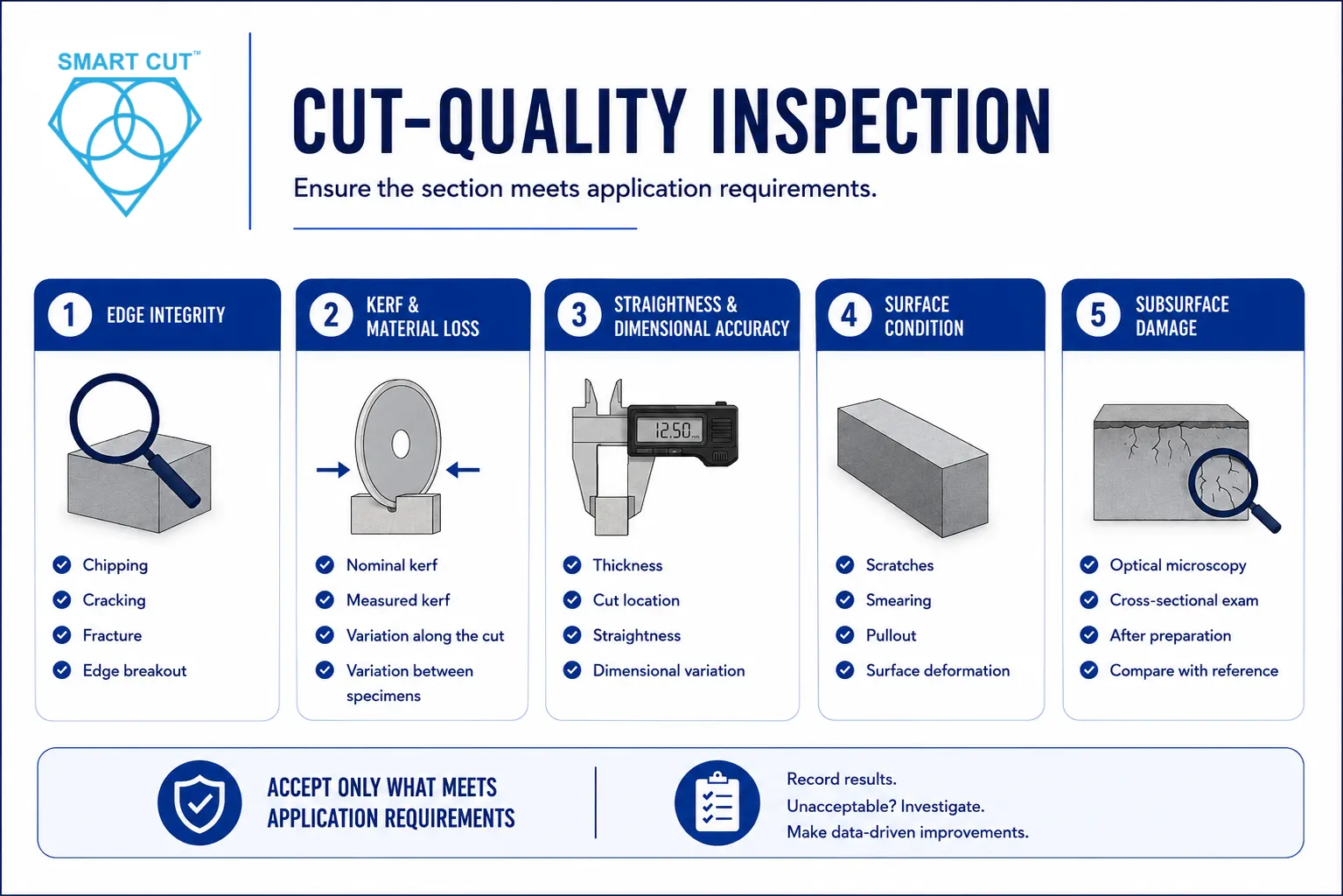
A precision cutting SOP should define not only how to produce a section but also how to determine whether the resulting specimen is acceptable.
Inspection requirements should be based on the actual application.
Depending on the laboratory, inspect:
- Edge condition
- Kerf
- Cut straightness
- Dimensions
- Surface condition
- Subsurface damage
- Thermal effects
- Material loss
- Blade condition
Edge Integrity
Inspect the sectioned edge for:
- Chipping
- Cracking
- Fracture
- Edge breakout
- Uneven damage
- Localized defects
For critical applications, optical magnification or another defined inspection method may be required.
The inspection method should remain consistent between samples.
If the laboratory has a validated edge-damage limit, use that requirement.
If it does not, the acceptance criterion should be established from the actual application rather than adopting an arbitrary universal limit.
Kerf and Material Loss
Kerf should be measured where dimensional control or material conservation is important.
Record:
- Nominal kerf
- Measured kerf
- Variation along the cut
- Variation between specimens
Unexpected kerf variation can indicate:
- Blade deflection
- Spindle runout
- Vibration
- Workpiece movement
- Blade wear
- Unstable cutting conditions
Kerf is therefore both a material-utilization measurement and a useful indicator of process stability.
Cut Straightness and Dimensional Accuracy
Measure the resulting specimen against the requirements of the application.
Possible characteristics include:
- Section thickness
- Cut location
- Straightness
- Parallelism
- Dimensional variation
The measurement equipment and method should be appropriate to the required tolerance.
For research specimens, dimensional consistency can also be important because specimen geometry can influence subsequent testing.
Surface Condition
Inspect the cut surface for:
- Scratches
- Smearing
- Pullout
- Surface deformation
- Burn marks
- Cracking
- Excessive roughness
The required surface condition depends on the downstream process.
A specimen intended for conventional metallographic grinding may have different sectioning requirements from a semiconductor cross-section requiring extremely low edge and subsurface damage.
Subsurface Damage
A visually acceptable surface does not necessarily mean that the section is free from cutting-induced damage.
Where subsurface integrity is important, the laboratory should define an appropriate examination method.
Depending on the application, this may involve:
- Optical microscopy
- Cross-sectional examination
- Examination after preparation
- Comparison with a qualified reference
- Other application-specific analytical methods
Subsurface damage should be treated as a measurable process characteristic when it can influence the final analytical result.
Cutting Acceptance Criteria
The SOP should define what constitutes an acceptable section.
Acceptance criteria should be application-specific.
For example, the laboratory may define requirements for:
| Characteristic | Acceptance Requirement | Actual Result | Status |
|---|---|---|---|
| Edge chipping | __________________ | __________ | Pass / Fail |
| Kerf | __________________ | __________ | Pass / Fail |
| Cut straightness | __________________ | __________ | Pass / Fail |
| Dimensions | __________________ | __________ | Pass / Fail |
| Surface condition | __________________ | __________ | Pass / Fail |
| Subsurface damage | __________________ | __________ | Pass / Fail |
| Material loss | __________________ | __________ | Pass / Fail |
| Blade condition | __________________ | __________ | Pass / Fail |
The laboratory should not use arbitrary limits simply because they appear precise.
An acceptance limit should have a reason behind it, such as:
- Drawing requirement
- Customer requirement
- Analytical requirement
- Internal quality standard
- Validated production history
- Qualified reference specimen
Controlled Deviation and Abnormal Results
Not every deviation requires rejection of the specimen or immediate revision of the SOP.
The laboratory should define how abnormal results are handled.
A deviation record should capture:
| Field | Record |
|---|---|
| Date | __________ |
| Operator | __________ |
| Machine | __________ |
| Blade | __________ |
| Material | __________ |
| Process Used | __________ |
| Observed Deviation | __________ |
| Immediate Action | __________ |
| Suspected Cause | __________ |
| Corrective Action | __________ |
| Final Disposition | __________ |
| Reviewer | __________ |
This creates a record that can later be used to determine whether the deviation was caused by the blade, machine, material, operator, or process.
Troubleshooting Common Cutting Problems
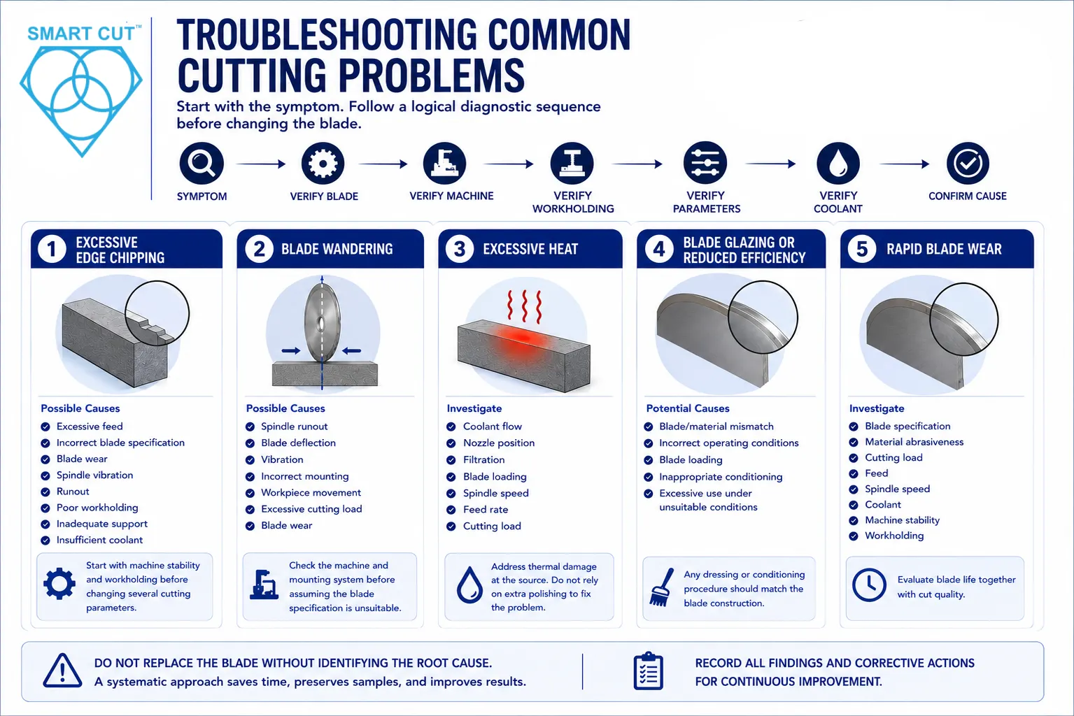
Troubleshooting should begin with the symptom rather than immediately replacing the blade.
A useful diagnostic sequence is:
Symptom → Verify Blade → Verify Machine → Verify Workholding → Verify Parameters → Verify Coolant → Confirm Cause
Excessive Edge Chipping
Possible causes include:
- Excessive feed
- Incorrect blade specification
- Blade wear
- Spindle vibration
- Runout
- Poor workholding
- Inadequate support
- Insufficient coolant
Start with machine stability and workholding before changing several cutting parameters.
Blade Wandering
Possible causes include:
- Spindle runout
- Blade deflection
- Vibration
- Incorrect mounting
- Workpiece movement
- Excessive cutting load
- Blade wear
Check the machine and mounting system before assuming the blade specification is unsuitable.
Excessive Heat
Investigate:
- Coolant flow
- Nozzle position
- Filtration
- Blade loading
- Spindle speed
- Feed rate
- Cutting load
Thermal damage should be addressed at the source rather than simply accepting a damaged specimen and increasing downstream polishing.
Blade Glazing or Reduced Cutting Efficiency
Potential causes include:
- Blade/material mismatch
- Incorrect operating conditions
- Blade loading
- Inappropriate conditioning
- Excessive use under unsuitable conditions
Any dressing or conditioning procedure should be appropriate for the specific blade construction.
Rapid Blade Wear
Investigate:
- Blade specification
- Material abrasiveness
- Cutting load
- Feed
- Spindle speed
- Coolant
- Machine stability
- Workholding
Blade life should always be evaluated alongside cut quality.
Worked Troubleshooting Example
Consider a laboratory that normally produces clean sections from a brittle ceramic but begins seeing increased edge chipping during a routine batch.
The operator reports that:
- The material specification has not changed.
- The blade specification is unchanged.
- The programmed RPM is unchanged.
- Chipping has increased significantly.
- Cutting resistance appears higher than normal.
Rather than immediately changing the feed rate, the investigation should proceed systematically.
Step 1: Compare With the Qualified Process
Check the recorded process conditions against the approved SOP.
Step 2: Inspect the Blade
Determine whether the blade shows abnormal wear, loading, or damage.
Step 3: Check Workholding
Confirm that the fixture has not loosened or changed alignment.
Step 4: Check Machine Condition
Inspect for abnormal spindle vibration, runout, or feed instability.
Step 5: Check Coolant
Confirm that flow and delivery have not changed.
Step 6: Check the Material
Verify material identity, thickness, orientation, and condition.
If the machine and workholding are stable but the blade shows significant wear, the blade becomes a stronger suspect.
If the blade is in good condition but spindle runout has increased, replacing the blade would not address the underlying problem.
This example illustrates why a structured SOP is valuable: it directs the investigation toward the actual process variables instead of encouraging trial-and-error changes.
Cleaning, Blade Care, and Post-Operation Procedure
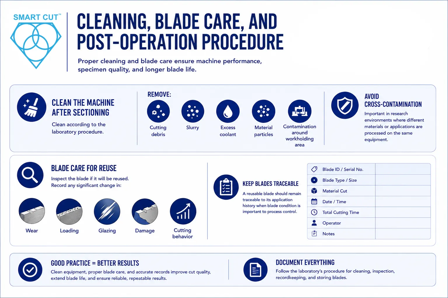
After sectioning, the machine should be cleaned according to the laboratory’s established procedure.
Remove:
- Cutting debris
- Slurry
- Excess coolant
- Material particles
- Contamination around the workholding area
Cleaning requirements should reflect the materials processed.
Cross-contamination can be particularly important in research environments where specimens from different materials or applications are processed on the same equipment.
If the blade will be reused, inspect its condition and record any significant change in:
- Wear
- Loading
- Glazing
- Damage
- Cutting behavior
A reusable blade should remain traceable to its application history when blade condition is important to process control.
Process Requalification
The SOP should define circumstances that require review or requalification.
Examples include significant changes to:
- Machine
- Spindle
- Blade specification
- Material
- Material thickness
- Workholding
- Coolant system
- Cutting parameters
- Inspection requirements
- Required cut quality
A process qualified for one machine and material combination should not automatically be assumed to remain qualified after a significant change to the cutting system.
Requalification should be based on the laboratory’s quality requirements and the significance of the change.
Precision Diamond Saw SOP Record Package
The article should not end with general advice. The laboratory should be able to turn the framework into a working controlled document.
A practical SOP package should contain the following records:
Document Control Record
Records SOP number, revision, effective date, author, reviewer, and approval.
Machine and Blade Identification Record
Records machine ID, blade manufacturer, part number, specification, diameter, and lot where required.
Pre-Operation Inspection Record
Confirms machine, blade, workholding, coolant, guarding, and setup condition.
Cutting Parameter Record
Records approved and actual RPM, feed rate, cutting depth, coolant, and other process variables.
Cut Inspection Record
Records edge condition, kerf, dimensions, straightness, surface condition, and other application-specific requirements.
Deviation and Troubleshooting Record
Documents abnormal results, investigation, corrective action, and final disposition.
Requalification Record
Documents significant process changes and the evidence used to approve the revised process.
This structure makes the SOP more than an instruction sheet. It becomes a controlled process record that can support repeatability, troubleshooting, quality review, and future process development.
Ready-to-Adapt Precision Diamond Saw SOP Template
The following structure can be used as the starting point for a laboratory’s controlled precision diamond saw procedure.
It should be adapted to the specific machine, blade, materials, safety requirements, inspection methods, and quality system of the laboratory.
Precision Diamond Saw Operating Procedure
SOP Number: __________________________
Revision: __________________________
Effective Date: __________________________
Machine ID: __________________________
Laboratory / Department: __________________________
A. Purpose
Define the approved procedure for precision sectioning of specified materials using the identified diamond saw and qualified cutting configuration.
B. Scope
Applicable machines:
Applicable materials:
Applicable applications:
C. Required Equipment
| Equipment / Item | Specification / Identification |
|---|---|
| Diamond saw | __________________ |
| Blade | __________________ |
| Fixture | __________________ |
| Coolant system | __________________ |
| Filtration | __________________ |
| Measurement equipment | __________________ |
| Other | __________________ |
D. Blade Specification
| Parameter | Approved Specification |
|---|---|
| Manufacturer | __________________ |
| Part Number | __________________ |
| Blade Type | __________________ |
| Diameter | __________________ |
| Thickness / Kerf | __________________ |
| Abrasive / Diamond Specification | __________________ |
| Bond / Construction | __________________ |
| Lot / Batch | __________________ |
E. Material Specification
| Parameter | Record |
|---|---|
| Material | __________________ |
| Grade | __________________ |
| Thickness | __________________ |
| Workpiece Dimensions | __________________ |
| Orientation | __________________ |
| Coating / Treatment | __________________ |
| Required Cut Location | __________________ |
F. Approved Cutting Parameters
| Parameter | Approved Value | Actual Value |
|---|---|---|
| Spindle Speed | __________ | __________ |
| Surface Speed, if used | __________ | __________ |
| Feed Rate | __________ | __________ |
| Cutting Depth | __________ | __________ |
| Number of Passes | __________ | __________ |
| Coolant Type | __________ | __________ |
| Coolant Concentration | __________ | __________ |
| Coolant Flow | __________ | __________ |
| Workholding Method | __________ | __________ |
G. Pre-Operation Verification
The operator should verify each applicable item before starting the cutting cycle.
| Verification | Pass / Fail | Notes |
|---|---|---|
| Correct machine | ☐ | __________ |
| Correct blade | ☐ | __________ |
| Blade condition acceptable | ☐ | __________ |
| Blade correctly mounted | ☐ | __________ |
| Spindle condition acceptable | ☐ | __________ |
| Workholding secure | ☐ | __________ |
| Workpiece correctly positioned | ☐ | __________ |
| Blade clearance confirmed | ☐ | __________ |
| Coolant available | ☐ | __________ |
| Coolant delivery verified | ☐ | __________ |
| Guarding verified | ☐ | __________ |
| PPE / safety requirements verified | ☐ | __________ |
Operator: __________________
Date: __________________
Initials: __________________
Cutting Operation Record
The operator should document the actual cutting conditions rather than relying only on the programmed machine settings.
Cutting Record
Work Order / Sample ID: __________________
Start Time: __________________
End Time: __________________
Operator: __________________
Machine ID: __________________
Blade ID: __________________
Material: __________________
Actual RPM: __________________
Actual Feed Rate: __________________
Cutting Depth: __________________
Coolant: __________________
Coolant Condition: __________________
Number of Passes: __________________
Abnormal Observations:
Operator Comments:
This record becomes particularly useful when multiple specimens are processed under the same SOP and one specimen produces an unexpected result.
Cut-Quality Inspection Form
The inspection record should reflect the characteristics that actually matter to the application.
Inspection Record
| Characteristic | Requirement | Actual Result | Pass / Fail |
|---|---|---|---|
| Edge chipping | __________ | __________ | ______ |
| Cracking | __________ | __________ | ______ |
| Kerf | __________ | __________ | ______ |
| Cut straightness | __________ | __________ | ______ |
| Dimensions | __________ | __________ | ______ |
| Surface condition | __________ | __________ | ______ |
| Subsurface damage | __________ | __________ | ______ |
| Thermal damage | __________ | __________ | ______ |
| Material loss | __________ | __________ | ______ |
Inspection Method: __________________________
Inspection Equipment: __________________________
Inspector: __________________________
Date: __________________________
Comments:
The laboratory should avoid creating acceptance fields that it cannot reliably measure.
If a characteristic is important enough to determine acceptance, the SOP should define how it is measured and what constitutes an acceptable result.
Troubleshooting Worksheet
When a cut fails to meet requirements, document the investigation rather than making undocumented adjustments.
Problem Identification
Sample ID: __________________
Observed Problem:
☐ Edge chipping
☐ Cracking
☐ Blade wandering
☐ Kerf variation
☐ Excessive heat
☐ Blade glazing
☐ Rapid blade wear
☐ Poor surface condition
☐ Slow cutting
☐ Other: __________________
Investigation
| Potential Cause | Checked? | Finding |
|---|---|---|
| Blade condition | ☐ | __________ |
| Blade specification | ☐ | __________ |
| Blade mounting | ☐ | __________ |
| Spindle runout | ☐ | __________ |
| Machine vibration | ☐ | __________ |
| Workholding | ☐ | __________ |
| Material condition | ☐ | __________ |
| Feed rate | ☐ | __________ |
| RPM | ☐ | __________ |
| Cutting depth | ☐ | __________ |
| Coolant flow | ☐ | __________ |
| Coolant delivery | ☐ | __________ |
Corrective Action
Cause Identified:
Corrective Action:
Result of Corrective Action:
Further Qualification Required?
☐ Yes
☐ No
Requalification Record
A change to the cutting process should be evaluated before assuming that the existing SOP remains valid.
Requalification Trigger
☐ New machine
☐ New blade
☐ New material
☐ Material thickness change
☐ New fixture
☐ Coolant change
☐ Cutting parameter change
☐ New inspection requirement
☐ Required cut quality changed
☐ Repeated process failure
☐ Other: __________________
Requalification Summary
Previous Process:
Change Introduced:
Trial Conditions:
Inspection Results:
Comparison With Previous Process:
Decision:
☐ Existing SOP remains valid
☐ SOP requires revision
☐ Additional testing required
Reviewed By: __________________
Approved By: __________________
Date: __________________
This record prevents significant process changes from being introduced informally and then treated as part of the existing qualified procedure.
The SOP should not necessarily specify only one operating point.
For some applications, it is more useful to establish a qualified operating window.
For example, a laboratory may evaluate several feed rates while keeping the blade, material, coolant, and machine constant.
The results can then be compared using:
- Edge quality
- Kerf
- Cutting time
- Blade wear
- Thermal condition
- Surface condition
- Dimensional accuracy
The laboratory can then establish an operating range that provides acceptable performance rather than relying on one isolated trial.
This approach also makes the SOP more useful when normal material variation occurs.
Connecting Sectioning to Downstream Analysis
The acceptance criteria for a precision cut should be determined by what happens to the specimen after sectioning.
A laboratory preparing samples for metallography may prioritize:
- Minimal structural alteration
- Reduced deformation
- Controlled edge condition
- Reasonable polishing allowance
A failure-analysis laboratory may place greater emphasis on:
- Preserving fracture features
- Minimizing subsurface damage
- Maintaining dimensional location
- Preventing contamination
A semiconductor laboratory may require particularly tight control of:
- Edge chipping
- Cross-section location
- Subsurface damage
- Thermal influence
- Package integrity
The SOP should therefore define acceptance criteria in relation to the analytical purpose of the specimen.
Why a Controlled SOP Improves Laboratory Repeatability
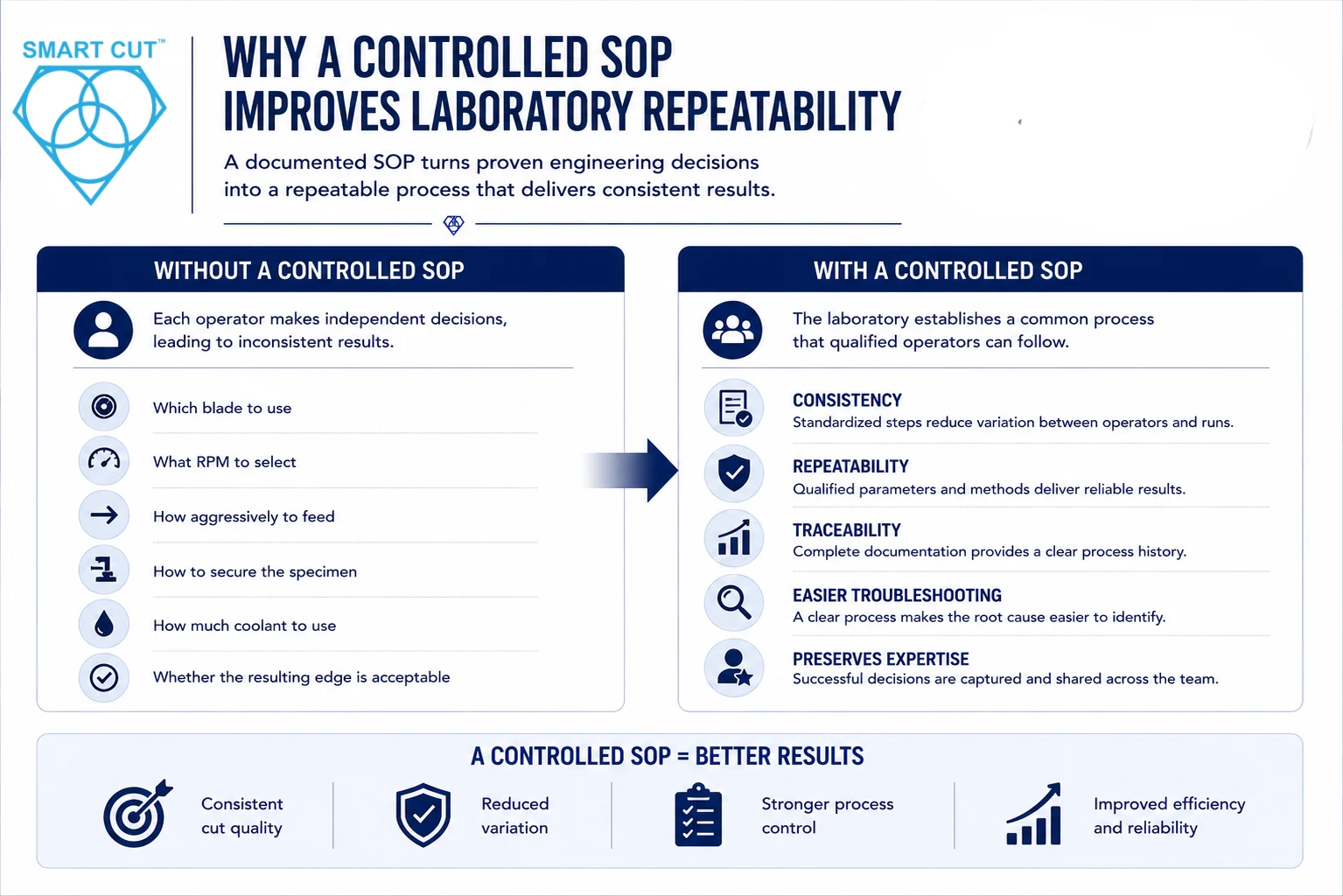
A documented SOP reduces the number of uncontrolled decisions made during routine sectioning.
Instead of each operator independently deciding:
- Which blade to use
- What RPM to select
- How aggressively to feed
- How to secure the specimen
- How much coolant to use
- Whether the resulting edge is acceptable
The laboratory establishes a common process.
This does not remove operator expertise.
It preserves that expertise by converting successful engineering decisions into a repeatable procedure that other qualified operators can follow.
The result is better process traceability and a clearer basis for troubleshooting when cutting performance changes.
Using SMART CUT® Equipment and Diamond Blades for Precision Sectioning
The appropriate cutting system depends on the material, specimen geometry, required precision, and laboratory workflow.
SMART CUT® precision cutting systems and diamond blades from UKAM Industrial Superhard Tools are relevant to applications where controlled sectioning and material preservation are important.
When evaluating a cutting configuration, laboratories should consider the complete system rather than selecting a blade independently from the machine.
The relevant engineering questions include:
- What material is being sectioned?
- What is the material thickness?
- What edge quality is required?
- How much material loss is acceptable?
- What dimensional accuracy is required?
- What level of subsurface damage can be tolerated?
- What machine is available?
- What coolant system is available?
- What inspection method will be used?
The blade and machine should then be evaluated against those requirements.
For laboratories developing a new application, the appropriate blade specification and operating conditions should be established from the material and process requirements rather than selected solely from a generic parameter table.
Where application-specific guidance is needed, UKAM’s applications engineering team can assist with evaluating the cutting configuration, blade selection, and process requirements.
What Should Be Included in the Downloadable SOP Package?
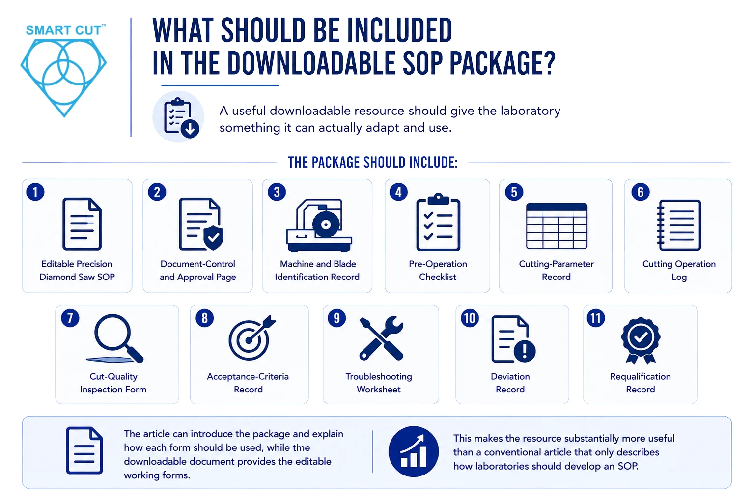
A useful downloadable resource should give the laboratory something it can actually adapt and use.
The package should include:
- Editable Precision Diamond Saw SOP
- Document-Control and Approval Page
- Machine and Blade Identification Record
- Pre-Operation Checklist
- Cutting-Parameter Record
- Cutting Operation Log
- Cut-Quality Inspection Form
- Acceptance-Criteria Record
- Troubleshooting Worksheet
- Deviation Record
- Requalification Record
The article can introduce the package and explain how each form should be used, while the downloadable document provides the editable working forms.
This makes the resource substantially more useful than a conventional article that only describes how laboratories should develop an SOP.
Frequently Asked Questions
A practical SOP should define the machine, blade, material, workholding, coolant, cutting parameters, operating sequence, inspection method, acceptance criteria, troubleshooting procedure, deviation process, and approval requirements.
No.
Cutting parameters depend on the machine, blade, material, geometry, thickness, and required result.
A laboratory should establish qualified parameters for each relevant application.
Blade selection should consider material hardness, brittleness, thickness, geometry, thermal sensitivity, required edge quality, material value, and machine capability.
The selected blade should be verified through manufacturer guidance and, where necessary, application-specific testing.
The SOP should define measurable acceptance criteria based on the purpose of the specimen.
These may include edge chipping, kerf, dimensional accuracy, straightness, surface condition, subsurface damage, thermal damage, or material loss.
At minimum, record the machine, blade, material, cutting parameters, coolant, workholding, operator, inspection results, and any abnormal observations required by the laboratory’s quality system.
Do not immediately change several parameters.
Check the blade, mounting, spindle condition, workholding, material, feed rate, RPM, cutting depth, and coolant delivery systematically to identify the likely cause.
Requalification should be considered after significant changes to the machine, blade, material, thickness, fixture, coolant, cutting parameters, inspection requirements, or required cut quality.
The overall framework can be reused, but the qualified blade, parameters, inspection criteria, and acceptance requirements should be specific to the material and application.
Documentation connects the final specimen to the conditions under which it was prepared.
This helps laboratories reproduce results, investigate unexpected findings, compare specimens, and determine whether a problem originated from the material or the sample-preparation process.
Precision diamond sawing should be treated as a controlled sample-preparation process rather than simply a material-removal operation.
The quality of the final specimen depends on the interaction between the:
Machine → Blade → Material → Workholding → Cutting Parameters → Coolant → Inspection
A strong SOP controls these variables without pretending that one set of parameters is suitable for every application.
For laboratories, the practical objective is to establish a procedure that is:
- Repeatable
- Measurable
- Traceable
- Application-specific
- Easy for qualified operators to follow
- Supported by defined inspection criteria
- Capable of controlled troubleshooting
- Reviewed when the process changes
The most useful SOP is therefore not simply a list of machine instructions. It is a controlled engineering document supported by actual process records.
When properly implemented, the procedure helps laboratories reduce avoidable edge damage, cracking, thermal effects, dimensional variation, material loss, and process-to-process variation while protecting the integrity of specimens used for research, quality control, failure analysis, and microscopy.
SMART CUT® precision diamond cutting systems and diamond blades from UKAM Industrial Superhard Tools provide options for laboratories working with demanding materials and precision sectioning requirements.
For a new material, unusual specimen geometry, or application where cut quality is critical, the correct starting point is to define the material and inspection requirement first, then establish the blade, machine configuration, cutting parameters, and acceptance criteria around that requirement.
Need help selecting a precision diamond blade or establishing cutting conditions for your material? Contact UKAM’s applications engineering team to discuss the specific material, machine, blade, and sectioning requirements.
Trusted by Tens of Thousands of Manufacturers, Laboratories,
Research Institutions Worldwide Since 1990
American Based Manufacturer
Established in 1990
Custom manufacturing
RELATED ARTICLES
Careful sample preparation is the key to good metallographic analysis. Although equipment features and process conditions are significant factors, the impact
