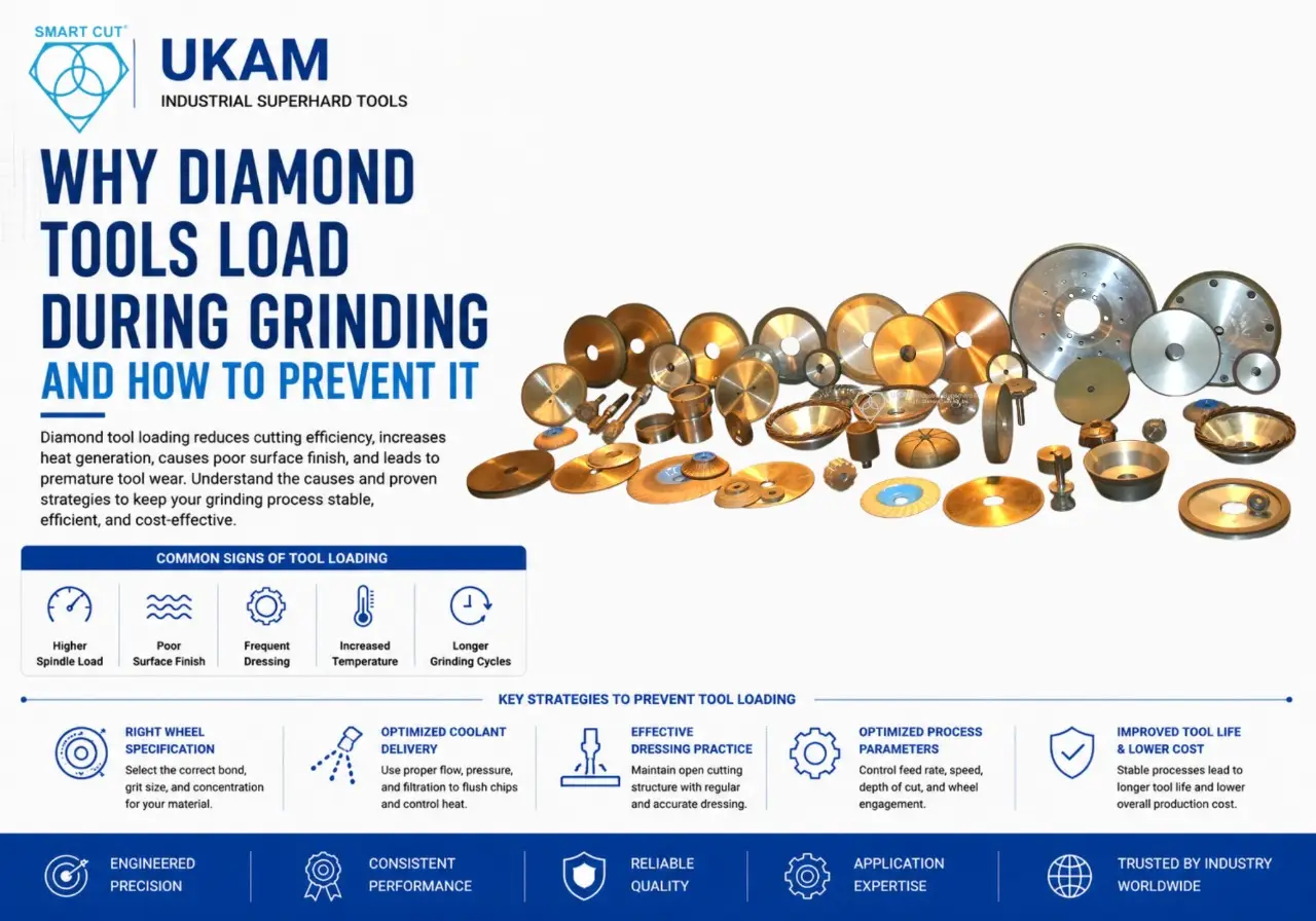


How to Switch Superabrasive Grinding Wheel Suppliers
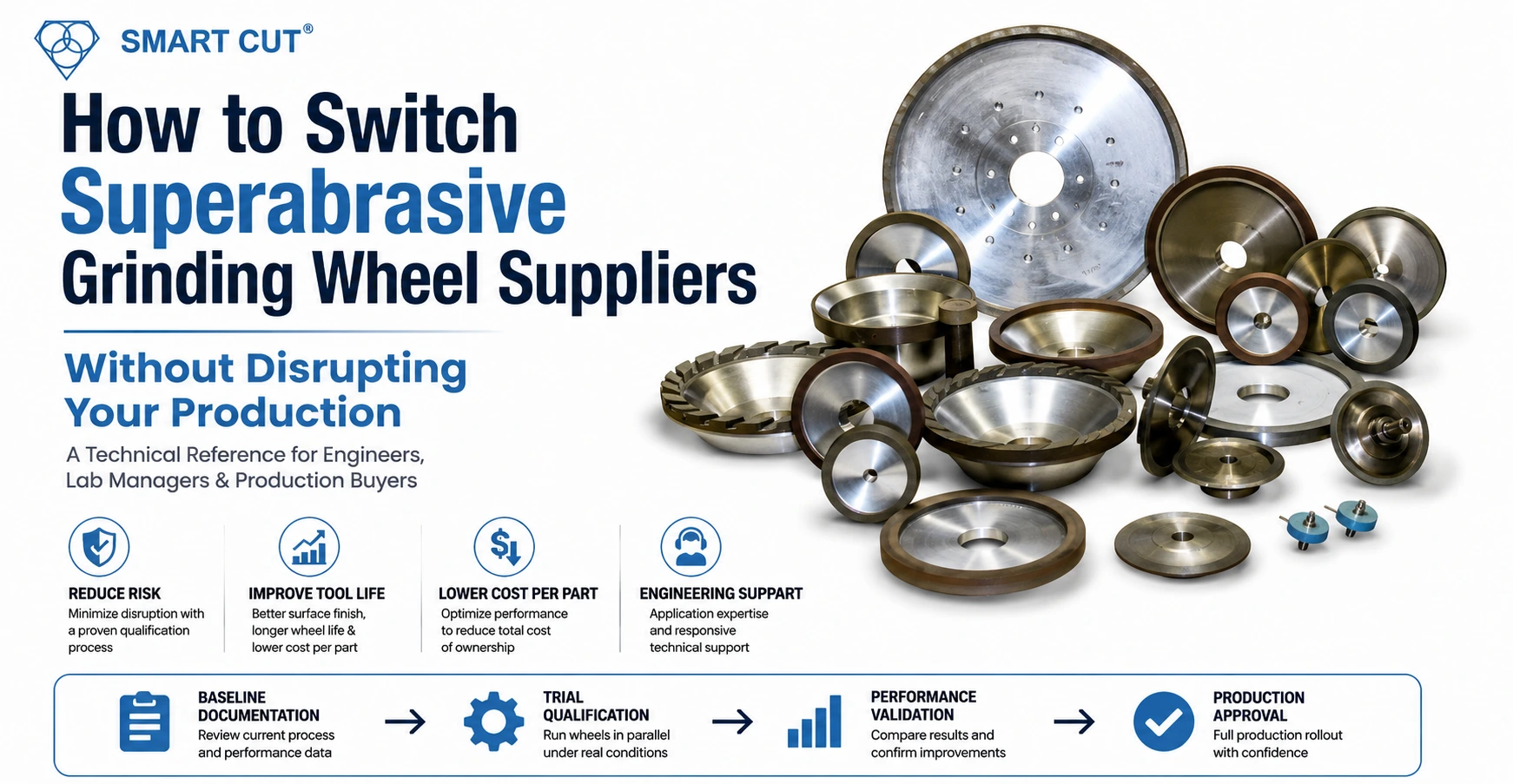
Table of Contents
Toggle
American Based Manufacturer

Established in 1990


Custom manufacturing


Without Disrupting Your Production
A technical reference for engineers, lab managers, and production buyers working with advanced materials
Switching grinding wheel or diamond tool suppliers is one of the most avoided decisions in precision manufacturing. The hesitation is understandable. A change in abrasive specification can shift surface finish, tighten or loosen dimensional tolerances, and alter cycle times in ways that take weeks to isolate and diagnose.
At the same time, staying with an underperforming supplier carries its own production cost: inconsistent tool life between lots, no real application engineering support, extended lead times on custom specifications, and tooling that was never matched to your specific material and machine parameters.
This guide covers what to assess before initiating a transition, how to run a controlled parallel trial without interrupting production, which technical parameters to verify during qualification, and how to calculate the true cost-per-part impact of a supplier change
Why Engineers Consider Switching Suppliers
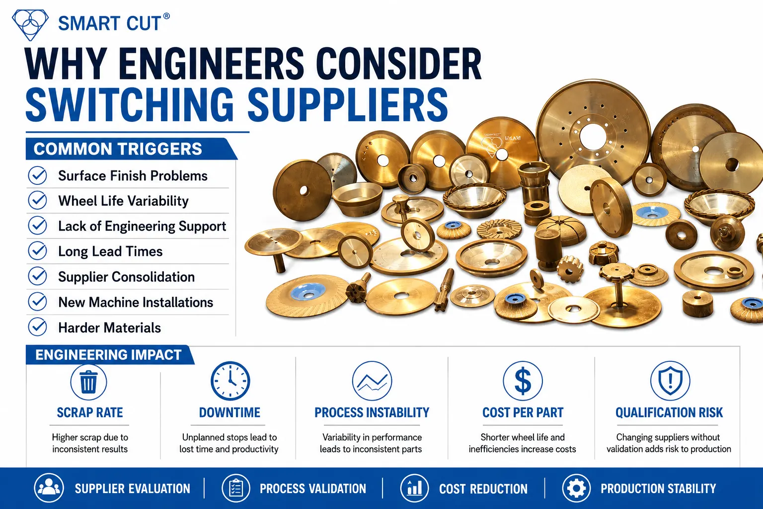
The decision rarely originates from price. It typically starts with a process problem the current supplier cannot solve, or with a technical gap that has simply become too costly to ignore
Common triggers:
- Surface finish degradation that persists despite parameter adjustments
- Inconsistent wheel life across production lots from the same supplier
- No application engineering support — only catalog recommendations
- Lead times on custom tools exceeding production schedules
- Supplier consolidation or discontinued product lines affecting availability
- New machine installation requiring re-optimized tooling
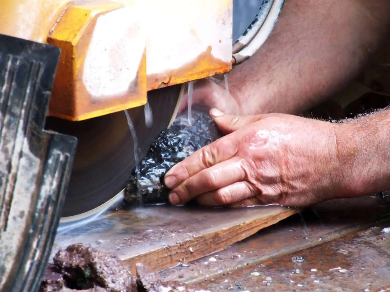
- Transition into harder or more brittle materials where generic tooling fails: silicon carbide, sapphire, alumina, fused silica, tungsten carbide
Technical Note: When a new CNC grinding center is installed, the previous wheel specification is frequently carried over unchanged. A machine with improved spindle rigidity, a higher RPM range, or a different coolant delivery system can support a fundamentally different bond system, grit concentration, or dressing strategy. New equipment represents one of the best opportunities to re-evaluate tooling from first principles
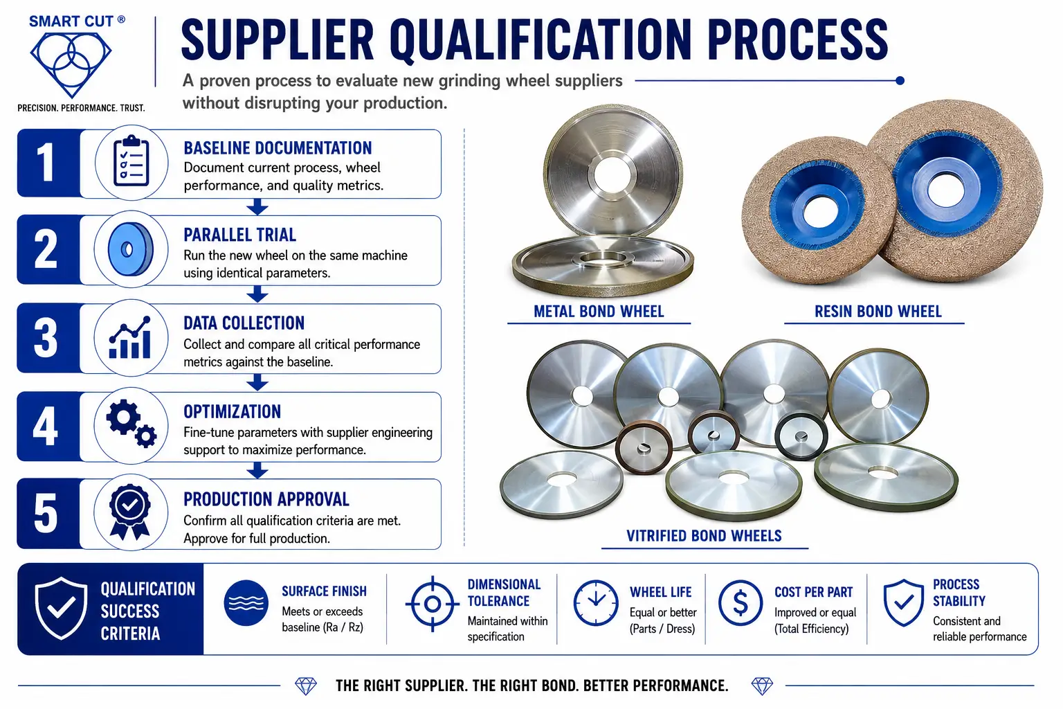
Before You Switch: Baseline Documentation
The most common failure in supplier transitions is insufficient baseline data capture before the first trial wheel arrives. Without this, there is no valid reference point for comparison.
The following parameters must be documented before any trial begins:
|
Problem at Interface |
Primary Cause |
Corrective Action |
|---|---|---|
|
Edge chipping |
Excessive feed rate at transition |
Reduce feed by 50 to 70% before interface |
|
Delamination |
Thermal shock from poor coolant |
Increase coolant flow at interface |
|
Transition cracking |
Wheel imbalance |
Balance to G2.5 minimum, G1.0 for precision |
|
Perimeter fracture |
Depth of cut too aggressive |
Reduce depth of cut to 0.001 to 0.003 mm at interface |
Without this data, the evaluation becomes a subjective comparison against a vague impression of previous tool performance. That is not a qualification; it is a guess.
Understanding True Cost Per Part
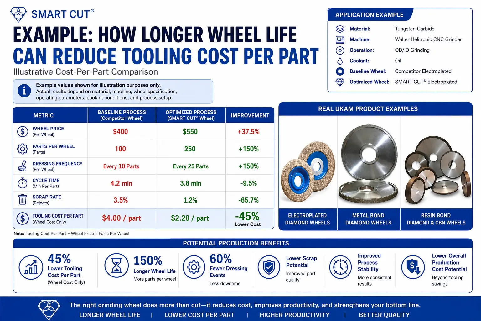
Engineers rarely switch suppliers based on purchase price alone, and they are right not to. The purchase price of a grinding wheel represents only one variable in the actual cost equation. Wheel life, dress interval, cycle time, and scrap rate all factor into the true cost per part.
The following comparison illustrates how a higher priced tool can reduce total production cost:
|
Variable |
Standard Sintered (Generic) |
SMART CUT Sintered (UKAM) |
Electroplated (Any Supplier) |
|---|---|---|---|
|
Bond matrix consistency |
Varies by batch; no stated chemistry control |
Proprietary bond chemistry; in-house manufacturing, Valencia CA |
Single-layer plating; consistent but limited life |
|
Wall thickness range |
Typically 1.0mm to 3.0mm standard |
0.5mm (ultra thin) to 4.0mm (heavy wall) |
Thin wall standard; heavy wall not typical |
|
Center-feed compatibility |
Varies; many not designed for water swivel |
Yes, compatible with water swivel adapters |
Depends on shank design |
|
Tool life with center-feed vs. flood |
Not documented by most suppliers |
40% to 75% longer life documented with center-feed |
Not applicable; electroplated tools are single-layer |
|
Available diameters |
Typically 0.5 inch to 12 inch standard catalog |
0.5 inch to 48 inch |
Typically 0.5 inch to 6 inch |
|
Recovery from glazing |
Possible with dressing if bond not destroyed |
Recoverable in most cases; bond maintains consistent cutting force over tool life |
Not recoverable; single-layer diamond lost permanently |
|
Best application fit |
General stone, construction, low-precision work |
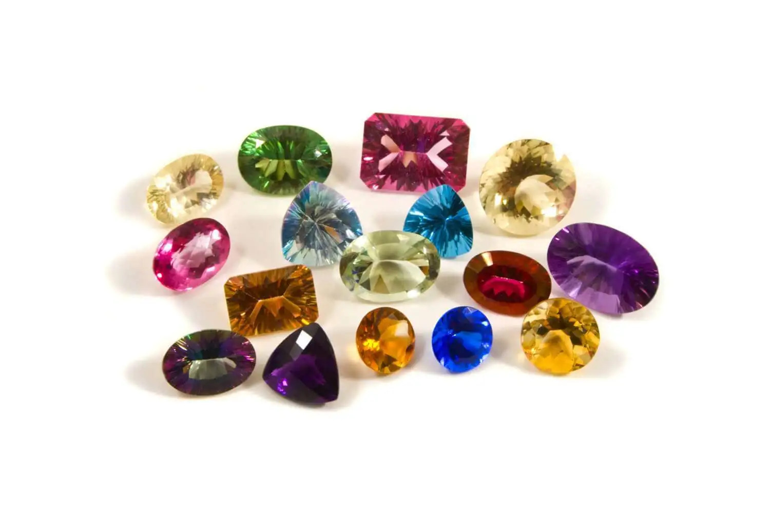
Optical glass, ceramics, sapphire, semiconductor, stone, precision production runs |
Very hard materials, thin walls, single-use or short-run applications |
Note: These figures are illustrative. Actual results depend on material, machine parameters, and application specifics. The structure of this calculation, however, applies directly to any superabrasive qualification process. Request application specific data from your supplier before committing to a changeover.
Engineering Principle: A wheel that costs 35% more per unit but lasts 2.5 times longer and reduces dress frequency will almost always deliver a lower cost per part. The purchase order price is the wrong metric for evaluating superabrasive tooling.
Bond System Selection
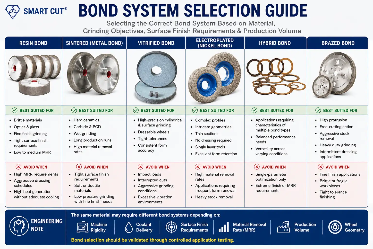
Changing suppliers is not solely a commercial transaction. If the new supplier recommends a different bond type, that recommendation must be grounded in your material properties, machine parameters, and surface finish requirements.
|
Material Layer |
Hardness (HV |
Thermal Conductivity |
Fracture Toughness |
Primary Challenge |
|---|---|---|---|---|
|
Polycrystalline Diamond Layer |
6,000 to 10,000 |
500 to 2,000 W/mK |
6 to 10 MPa·m½ |
Diamond-on-diamond interaction, graphitization risk above 700°C |
|
Tungsten Carbide Substrate |
1,300 to 1,800 |
80 to 100 W/mK |
10 to 15 MPa·m½ |
Brittle fracture at high grinding forces |
|
Transition Zone (Interface) |
Gradient |
Gradient |
Lowest in structure |
Delamination, chipping, thermal shock cracking |
Critical: Never assume a wheel from a new supplier with the same grit size and bond label will perform identically to your current tool. Diamond concentration, crystal type, crystal friability, and bond matrix formulation all vary by manufacturer, and all affect how the wheel cuts and wears.
How to Run a Parallel Trial Without Stopping Production
A controlled parallel trial is the lowest-risk method for qualifying new tooling. The objective is an apples-to-apples comparison under identical conditions before any parameter optimization begins.
Phase 1: Baseline Lock (1 to 2 weeks before trial)
- Run current tooling for a minimum of 50 to 100 parts
- Record all parameters from the baseline documentation table above
- Log dress intervals and note any anomalies in wheel behavior
Phase 2: Trial Setup
- Install the new wheel on a machine running the same grinding operation
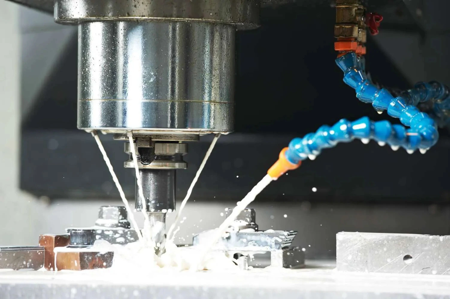
- Use identical machine parameters as the baseline: same RPM, feed rate, dress frequency, and coolant
- Do not adjust parameters to compensate for early trial behavior
Phase 3: Data Collection
- Run the same number of parts as the baseline run
- Record all parameters identically to baseline documentation
- Note self-correcting behavior: resin bond wheels often improve over the first 20 to 30 parts as the bond matrix opens
Phase 4: Parameter Optimization
- Begin optimization only after baseline comparison is complete
- A qualified supplier provides starting parameter recommendations based on your application, not generic catalog tables
- Document every parameter change and the measured result
Engineering Insight: The best-performing wheel is rarely the one that matches your current specification exactly. It is the one engineered for your specific material, machine, and quality requirement. That may mean a different grit concentration, a modified bond formulation, or an entirely different bond system.
Material-Specific Considerations During Qualification

Different advanced materials react very differently to changes in abrasive specification. The failure modes, inspection methods, and critical parameters vary significantly by material family.
Silicon Carbide and Advanced Ceramics
- Surface finish is highly sensitive to grit size and bond hardness variations
- Subsurface damage (SSD) can be present even when surface Ra appears acceptable
- Sectioning or cross-section inspection is recommended when tight tolerances are involved
- Bond hardness and diamond concentration have a direct effect on SSD depth
Sapphire and Hard Optical Materials
- Edge chipping at entry and exit is the primary failure mode to monitor
- Resin bond with lower concentration generally reduces chipping compared to metal bond at equivalent grit
- Dressing interval has a disproportionate effect on edge quality in sapphire grinding
- Wheel loading in sapphire is less common than in ceramics but increases risk of thermal damage
Semiconductor Materials (Silicon, GaAs, InP)
- Subsurface damage depth is the critical metric, not surface finish alone
- Bond system and crystal friability directly influence SSD depth
- Higher-friability diamond crystals tend to produce shallower SSD in brittle semiconductors
- Always inspect for SSD using cross-section or preferably angle polishing and etching
Composites (Carbon Fiber, Glass Fiber, Aramid)
- Fiber type drives bond selection: carbon fiber applications tolerate harder bonds than aramid
- Delamination at exit edges is the most common failure mode to monitor
- Lower feed rates at entry and exit reduce delamination risk when trialing new tooling
Glass and Fused Silica
- Fine grit, well-dressed resin bond is required for optical surface quality
- Coolant temperature stability matters: thermal expansion affects dimensional tolerance at tight specs
- Wheel loading produces immediate surface finish degradation in optical glass applications
Tungsten Carbide and PCD
- Both materials require aggressive diamond concentration and a bond system that supports continuous edge renewal
- Metal bond and electroplated tools are most common for roughing; resin bond for finishing
- CVD diamond tooling applies for high-volume PCD grinding where profile accuracy is critical
What to Ask a New Supplier Before Committing
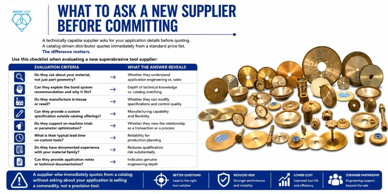
A technically capable supplier asks for your application details before quoting. A catalog-driven distributor quotes immediately from a standard price list. The difference matters.
Use this checklist when evaluating a new superabrasive tool supplier:
|
Mechanism |
Dominant Condition |
Primary Risk if Uncontrolled |
|---|---|---|
|
Mechanical micro-fracture |
Sharp diamond grits, low thermal load |
Subsurface crack propagation |
|
Intergranular fracture |
Coarse grit, high feed rate |
Surface roughness, edge pullout |
|
Transgranular fracture |
Fine grit, high wheel speed |
Deeper subsurface damage |
|
Thermochemical oxidation |
Temperature above 600°C in air |
Diamond graphitization, permanent hardness loss |
|
Micro-plastic deformation |
High pressure at abrasive tip |
Wheel glazing, rising grinding force |
A supplier who immediately quotes from a catalog without asking about your application is selling a commodity, not a precision tool.
SMART CUT Technology: What It Means for Supplier Transitions
UKAM’s SMART CUT technology is a bond matrix and diamond crystal formulation system engineered to self-renew during the cutting process. As worn diamond crystals are released, fresh cutting points are exposed at a controlled rate. This is a mechanically meaningful design, not a marketing descriptor.
The practical implications for engineers evaluating a supplier transition:
|
Symptom |
Most Likely Cause |
Corrective Action |
|---|---|---|
|
Rising spindle load |
Bond hardness too high for material |
Specify softer bond grad |
|
Surface burning |
Wheel glazing combined with poor coolant |
Dress wheel, improve coolant delivery |
|
Poor material removal rate |
Diamond concentration too low |
Increase concentration to 100 to 125% |
|
Elevated grinding temperature |
Inadequate coolant penetration |
Increase coolant pressure to minimum 40 bar |
|
Rapid wheel wear after dressing |
Incorrect diamond friability |
Specify tougher crystal grade |
These characteristics are the result of a specific bond matrix formulation that controls diamond retention and release rate. For applications involving brittle materials, tight tolerances, or high-value components, the reduction in process variability has a measurable impact on yield and scrap rate.
Qualification Checklist: Declaring a Trial Successful
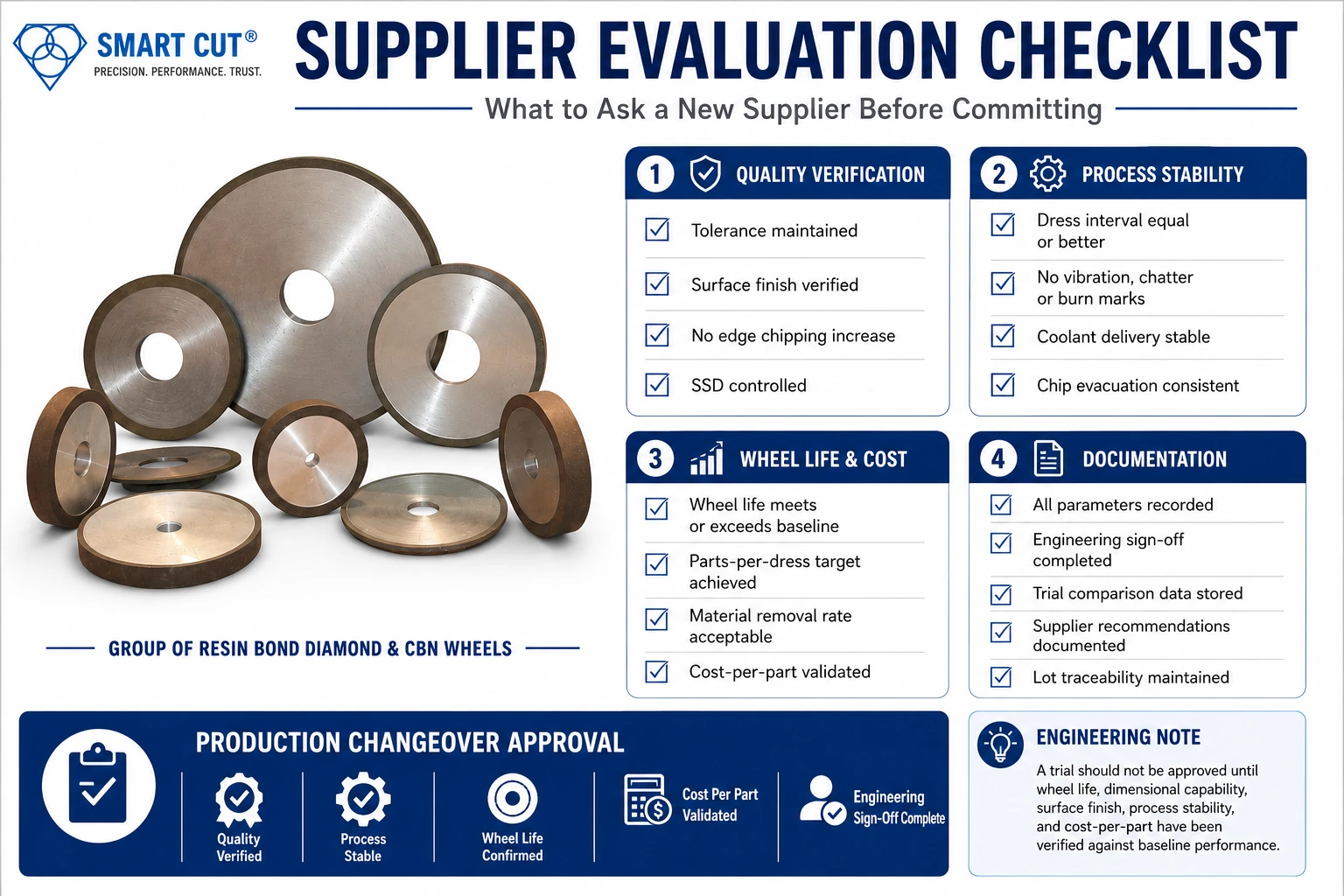
Dimensional and Surface Quality
- Dimensional tolerance held to specification across the full trial run
- Surface finish (Ra/Rz) matches or exceeds baseline
- No increase in edge chipping or subsurface damage where applicable
- No wheel loading behavior observed during or after the trial run
Process Stability
- Dress interval consistent and equal to or better than baseline
- No anomalous vibration, chatter, or burn marks during the run
- Coolant and chip evacuation behaving normally throughout
Life and Efficiency
- Wheel life (parts per dress and total wheel life) meets or exceeds baseline
- Material removal rate acceptable for cycle time requirements
- Cost-per-part calculation complete and validated against baseline
Documentation
- All parameters recorded and signed off by engineering
- Comparison data filed for future reference and lot traceability
- Supplier parameter recommendations on file
FAQ: Switching Superabrasive Grinding Wheel Suppliers
For a straightforward application, two to four weeks is typical. That allows time for a meaningful baseline run and a parallel trial with sufficient part count. Complex applications involving tight tolerances, brittle materials, or high-value components may require six to ten weeks. Compressing this timeline is the most common cause of failed transitions. A failed qualification in production costs far more than a thorough trial in a controlled environment.
Outer dimensions, bore, grit size, and bond type label can all be matched. Internal bond formulation, diamond concentration, crystal type, and crystal friability will differ between manufacturers. Dimensional equivalence does not equal functional equivalence. Performance must always be validated through a parallel trial, even when the specification on paper appears identical.
Surface finish degradation and unexpected changes in wheel life are the two most visible issues. Subsurface damage in brittle materials is the less visible but higher-risk failure mode. It requires destructive inspection, cross-section analysis, or angle polishing to detect, and it will not appear in surface Ra measurements until damage levels are already significant.
Working adequately is not the same as working optimally. Inconsistent lead times, absence of engineering support, inability to obtain a custom specification, and lot-to-lot variability are all valid reasons to evaluate alternatives even without an active performance failure. A transition executed on your schedule, with a controlled parallel trial, is far preferable to an emergency switch forced by supply disruption.
- Material being processed, including grade or hardness where relevant
- Required surface finish and dimensional tolerance
- Machine type, spindle speed range, and coolant setup
- Current wheel specification if replacing an existing tool
- Production volume: R&D, low-volume production, or high-volume production run
Yes. UKAM’s application engineering team works with customers through tool selection, starting parameter recommendations, and trial support, including specification adjustments based on trial results. This support is particularly relevant for applications involving advanced ceramics, photonics substrates, semiconductor materials, and other precision-sensitive materials where generic tooling frequently fails.
UKAM manufactures tools across all major bond systems: Sintered Metal Bond, Resin Bond, HYBRID Bond, Electroplated Nickel Bond, Brazed Bond, Vitrified Bond, and CVD diamond tools. Custom specifications are available for applications where standard catalog products do not meet the required geometry, concentration, or surface finish specification.
Key Principles for a Successful Supplier Transition
- Document your baseline before any trial. No baseline means no valid comparison, and no valid comparison means no defensible qualification.
- Match machine parameters exactly in Phase 1 of the trial. Optimize only after baseline data is captured and confirmed.
- Bond type label does not equal bond performance. Formulations vary significantly between manufacturers, and only a trial establishes functional equivalence.
- Choose a supplier with in-house manufacturing and genuine application engineering, not a catalog-driven distributor without technical depth.
- Allow adequate qualification time. Compressed timelines are the primary cause of failed supplier transitions.
- New machine installations are the best window to re-evaluate tooling from first principles rather than carrying over a specification that was never optimized for the new equipment.
- Cost-per-part, not purchase price, is the correct metric for evaluating superabrasive tooling.
Trusted by Tens of Thousands of Manufacturers, Laboratories,
Research Institutions Worldwide Since 1990
American Based Manufacturer
Established in 1990
Custom manufacturing
RELATED ARTICLES