








































How to Choose the Right Diamond Grinding Wheel for Precision Manufacturing

Table of Contents
Toggle
American Based Manufacturer

Established in 1990


Custom manufacturing


Choose a diamond grinding wheel by matching the abrasive, bond, grit, concentration, and geometry to your material and grinding operation. Then verify that the wheel can produce acceptable parts on your machine at a practical cycle time and cost.
A wheel that fits the spindle can still cause loading, excessive heat, poor finish, edge damage, or dimensional drift. Selection should begin with the finished part requirements and the conditions at the grinding contact.
UKAM Industrial Superhard Tools manufactures standard and custom diamond and CBN wheels. We help you evaluate wheel specifications against your material, equipment, quality requirements, and production objectives.
Start with these selection decisions
|
Decision |
What to establish |
|---|---|
|
Abrasive |
Confirm whether diamond, CBN, or another abrasive suits the workpiece. |
|
Operation and geometry |
Define the grinding contact, required profile, wheel dimensions, and mounting. |
|
Bond |
Match abrasive retention, form retention, and conditioning needs to the process. |
|
Grit |
Balance stock removal with roughness, edge quality, and surface integrity. |
|
Concentration |
Select abrasive content together with grit, bond, contact area, and machine capacity. |
|
Qualification |
Confirm repeatable quality, useful wheel life, cycle time, and cost per acceptable part. |
Request help selecting a grinding wheel. Send your material, wheel dimensions or drawing, machine information, and the result you need to improve.
Confirm abrasive compatibility and material condition
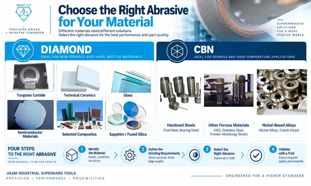
Diamond commonly serves tungsten carbide, technical ceramics, glass, crystalline materials, and selected composites. CBN is commonly selected for hardened steels and certain other ferrous or nickel-based applications. Conventional grinding of steel generally requires a different abrasive choice from grinding carbide or glass.
Record the exact material grade and condition. Hardness, abrasiveness, binder content, reinforcement, and microstructure can change the wheel specification even when two workpieces have the same general material name.
|
Workpiece |
Information that changes the selection |
|---|---|
|
Tungsten carbide |
Carbide grain size, binder type and content, stock removal, edge requirements, and the amount of binder exposed at the surface. |
|
PCD grade, diamond grain size, and binder where present. For carbide-backed blanks, establish whether grinding reaches the substrate or the interface. |
|
|
Alumina |
Purity, grain structure, porosity, and edge support. Account for grain pullout and chipping when setting finish requirements. |
|
Identify the specific grade and manufacturing condition. Evaluate removal rate, abrasive wear, edge condition, and subsurface integrity where required. |
|
|
Record crystal orientation for sapphire where relevant. For both materials, define permitted edge damage and subsurface damage separately from roughness. |
|
|
Identify the composition, thickness, support method, and permitted defects. Match grinding and material handling controls to the actual substrate. |
For a multilayer or composite workpiece, identify every material the wheel contacts. A specification selected for one layer may respond differently when it reaches a metal backing, reinforcement, or bonded interface.
Explore UKAM diamond and CBN wheels for available wheel constructions and application options.
Define the operation and acceptance requirements
Specify whether you are surface grinding, cylindrical grinding, internal grinding, sharpening a tool, generating a profile, or thinning a substrate. Record the total stock allowance and the amount removed per pass. A broad contact area can place different demands on the wheel and machine than a narrow profile contact.
Set separate limits for dimensions, form, roughness, edge condition, and surface integrity. For example, an Ra requirement describes average profile roughness. It does not by itself define acceptable chipping, waviness, microcracking, or thermal damage.
For an existing process, record the current wheel and the failure that limits production. State whether the objective is to improve quality, shorten the cycle, extend useful life, reduce conditioning, or lower total cost. A wheel change can be worthwhile even when the current wheel meets the drawing requirements.
Choose a bond with the right cutting and conditioning behavior
The bond holds the abrasive and influences how the working surface develops during use. Choose it together with grit, concentration, wheel geometry, and your available conditioning equipment. Bond names describe broad families. Formulations within the same family can behave differently.
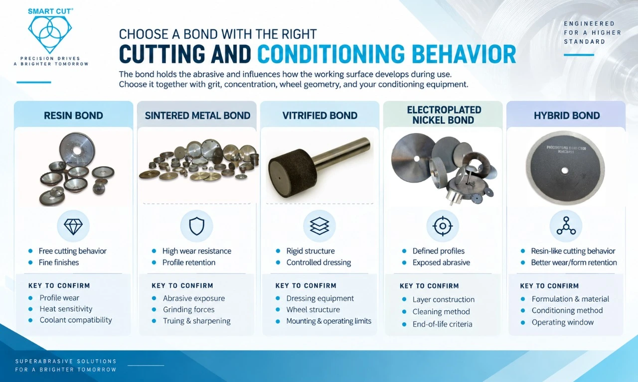
|
Bond construction |
Reasons to consider it |
What to confirm |
|---|---|---|
|
Free cutting behavior and fine finishes. Often considered for carbide tool grinding and finishing. |
Profile wear, heat sensitivity, coolant compatibility, and conditioning interval. |
|
|
Applications where wear resistance and retention of the wheel profile are important. |
Abrasive exposure, grinding forces, and an effective method of truing and sharpening. |
|
|
Precision grinding that benefits from a rigid structure and controlled dressing. Porous formulations can provide space for coolant and debris. |
Available dressing equipment, wheel structure, mounting, and approved operating limits. |
|
|
Defined profiles and exposed abrasive on a shaped core. Useful where access and geometry are important. |
Abrasive layer construction, initial surface condition, cleaning method, and end-of-life criteria. |
|
|
Grinding that needs resin-like cutting behavior with improved wear or form retention from a combined bond formulation. |
The actual formulation and its intended material, conditioning method, and operating window. |
When dimensional drift comes from profile wear, a construction with better form retention may help. When load rises because the abrasive surface becomes dull or loaded, stronger retention alone may make the problem worse. Review abrasive exposure and conditioning before changing the bond.
Compare diamond bond types and discuss the appropriate construction for your grinding operation with UKAM.
Select grit for stock removal and the required surface
Coarser abrasive generally creates larger cutting engagements and is a candidate for higher stock removal. Finer abrasive is a candidate when surface roughness and edge quality are the main constraints. The final choice also depends on bond, abrasive exposure, contact area, feed, depth of cut, and material response.
|
Production need |
Starting direction |
Trial evidence |
|---|---|---|
|
Remove substantial stock |
Evaluate a coarser grit in a construction suited to the material. Leave a controlled allowance if finishing follows. |
Removal rate, load, wear, chipping, and damage remaining for the finishing step. |
|
Improve finish or edge quality |
Evaluate a finer grit with controlled engagement and effective conditioning. |
Roughness, edge defects, cycle time, loading, and integrity requirements. |
|
Improve dimensional consistency |
Check wheel form, mounted runout, support, and thermal stability before making grit the main change. |
Dimensions and form measured in production order, alongside wheel condition. |
Read the grit designation carefully. Within the same mesh grading system, 100/120 mesh is coarser than 270/325 mesh. In a specification stated directly in micrometers, a 15 to 25 µm particle range is finer than a 40 to 60 µm range. These examples explain size notation. They are not application recommendations or conversions between grading systems.
Ask for the grading system and particle size range when comparing quotations. Mesh numbers, micron ranges, and other abrasive designations should be compared using the applicable grading reference.
A separate roughing and finishing wheel may improve the overall process when one specification cannot satisfy both removal rate and surface requirements. Evaluate the added setup and handling time before choosing a two-stage process.
Select concentration with the full wheel specification
Diamond concentration describes abrasive content within the bonded working layer. Under the conventional diamond concentration scale, C100 corresponds to approximately 25% diamond by volume, or 4.4 carats per cubic centimeter. C50 corresponds to approximately 12.5% by volume. A C100 marking does not mean that the wheel contains 100% diamond.
Higher abrasive content can distribute engagement over more particles and help resist wear in some applications. It also changes particle spacing and the load carried by each active grain. The effect on cutting ability, loading, force, and finish depends on the grit, bond structure, contact geometry, and operating conditions.
Select a starting concentration within the range appropriate to the wheel construction. If the wheel loses abrasive or profile rapidly, check the wear mechanism and bond retention. If it rubs, loads, or requires excessive force, examine grit spacing, abrasive exposure, engagement, and conditioning before changing concentration.
Avoid assigning concentration from material hardness alone. Hardness and abrasiveness describe different material characteristics. For plated constructions, confirm how abrasive density and layer structure are specified rather than assuming that bonded-wheel concentration numbers describe the plated surface.
Specify the working geometry and mounting
Provide a drawing whenever the wheel must generate a defined radius, angle, groove, or profile. Specify the outside diameter, bore or shank, axial width, abrasive working width, radial or axial abrasive depth, core clearances, and mounting features. Identify which surface is intended to grind the part.
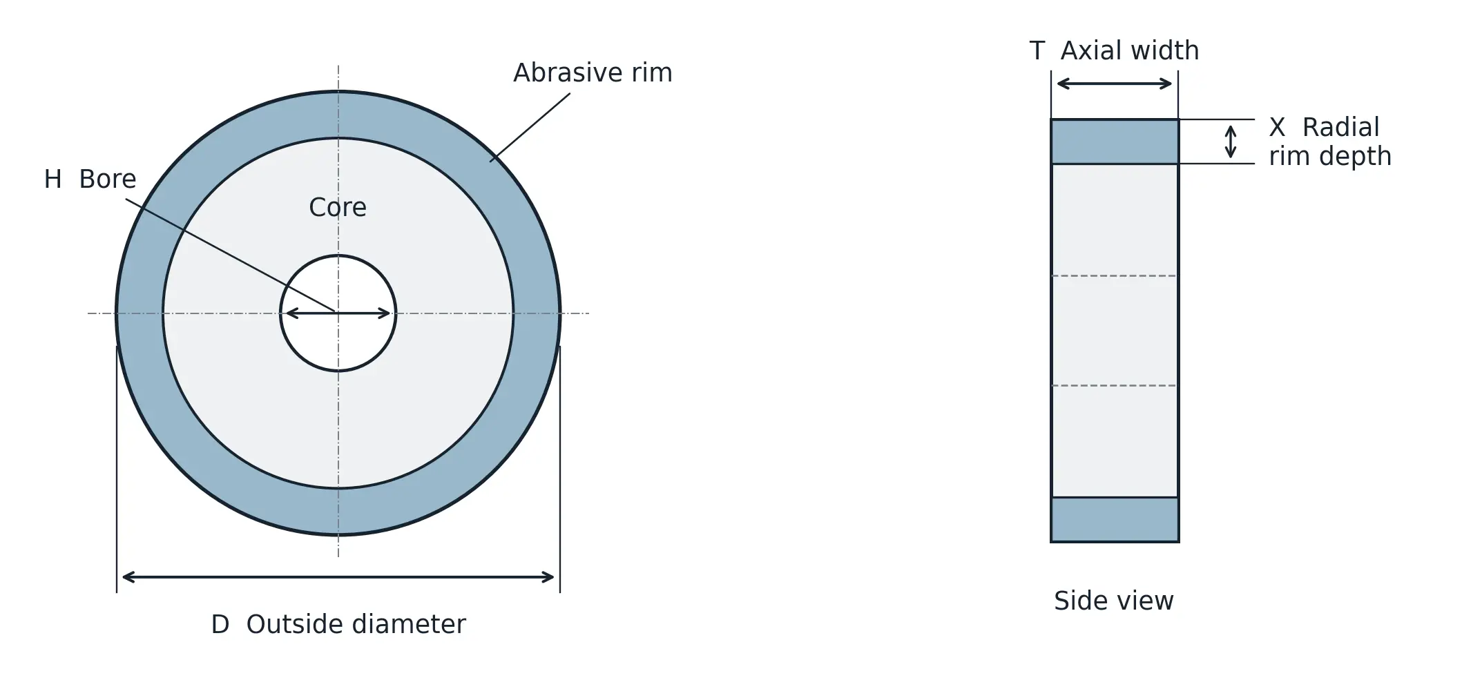
Illustrative straight peripheral wheel. The abrasive spans the full axial width in this example. Other constructions have different working widths, profiles, and abrasive placement. This schematic is not a manufacturing drawing.
A straight peripheral wheel, cup wheel, dish wheel, and V-profile wheel contact the part differently. Select the shape for access, support, clearance, and the surface being generated. Use the approved working surface and loading direction for the specific wheel.
View straight diamond and CBN grinding wheels as one example of a geometry that can be specified for the operation.
Check surface speed as well as RPM
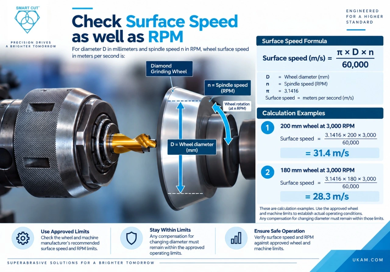
For diameter D in millimeters and spindle speed n in RPM, wheel surface speed in meters per second is:
Surface speed = (π × D × n) / 60,000
A 200 mm wheel at 3,000 RPM runs at approximately 31.4 m/s. At 180 mm and the same RPM, it runs at approximately 28.3 m/s. These are calculation examples. Use the approved wheel and machine limits to establish actual operating conditions. Any compensation for changing diameter must remain within those limits.
Confirm machine capability and coolant delivery
Check the available spindle speed, power, torque, rigidity, workholding, mounting, and conditioning capability before finalizing the wheel. Measure runout on the mounted assembly at a defined location. An arbor measurement alone does not establish running accuracy at the abrasive surface.
For internal or narrow-access grinding, pay particular attention to overhang and deflection. For thin or brittle parts, verify that the support and clamping method remain stable as material is removed.
Coolant must reach the active contact and carry away heat and debris. Record fluid type, actual concentration where relevant, flow, pressure, filtration, temperature, and nozzle position. Pump capacity and visible coolant around the part do not establish effective delivery into the grinding zone.
A useful setup review includes a photograph or video showing the wheel contact, fixture, nozzle position, and a complete grinding cycle. This helps connect the wheel specification with what happens during entry, steady grinding, and exit.
Interpret spindle load in context
Record load trends with cycle time, wheel condition, dimensions, and finish. Compare measurements from the same machine and record how its load display is scaled. A displayed load percentage is not a direct measurement of normal grinding force.
Tangential force multiplied by wheel surface speed gives mechanical grinding power at the wheel. For illustration, 145 N at 4,000 surface feet per minute corresponds to approximately 2.95 kW. At 112 N and 7,500 surface feet per minute, the result is approximately 4.27 kW. Lower force at a higher speed can therefore require more power. Thermal condition also depends on heat distribution, contact time, and cooling.
Match conditioning to the wheel construction
Truing establishes wheel shape and running accuracy. Dressing or sharpening prepares the abrasive surface to cut. Depending on the wheel and equipment, these may be separate operations or part of one process.
For resin, metal, vitrified, and hybrid bonded wheels, confirm the conditioning tool, engagement, speed, coolant, and procedure for that specific construction. Establish an interval from changes in finish, dimensions, load, removal rate, and wheel condition.
Conventional single-layer electroplated wheels do not contain successive abrasive layers that routine dressing can expose. Use the approved cleaning or conditioning method. Other plated constructions require their own instructions. A procedure for a bonded wheel should not be transferred automatically to a plated wheel.
When conditioning restores acceptable results, record how long that improvement lasts. Increasingly short intervals can indicate a mismatch among the wheel, process conditions, and conditioning method. Include conditioning time and abrasive loss when evaluating useful wheel life.
Review electroplated diamond and CBN wheel options and confirm the care procedure for the selected construction.
Use the observed problem to choose the next check
Record when a defect begins, where it appears, and whether it changes after conditioning or a setup adjustment. Use that evidence to prioritize checks. Similar symptoms can have different causes.
|
Observed condition |
First checks |
|---|---|
|
Poor finish from the first parts |
Measure abrasive or profile loss against stock removed. Review bond retention, material abrasiveness, and conditioning loss.Verify mounted runout, wheel condition, workholding, grit, and the measurement method. |
|
Finish deteriorates during the run |
Compare part sequence with loading, abrasive wear, conditioning history, and coolant changes. |
|
Dimensional drift or loss of form |
Check wheel wear and profile, thermal change, compensation, and movement under clamping. |
|
Chipping or edge breakout |
Inspect the defect location, entry and exit conditions, support, engagement, and vibration. |
|
Rising load or excessive heat |
Check abrasive exposure, loading, stock removal, and coolant delivery at the contact. |
|
Rapid wheel wear |
Measure abrasive or profile loss against stock removed. Review bond retention, material abrasiveness, and conditioning loss. |
|
Chatter or repeating marks |
Measure abrasive or profile loss against stock removed. Review bond retention, material abrasiveness, and conditioning loss.Check mounted accuracy, balance where required, spindle condition, overhang, and workholding. |
For example, acceptable results immediately after conditioning followed by rising load and poorer finish support a review of working-surface condition and the interval between conditioning operations. They do not prove that grit or bond is the sole cause.
Qualify the wheel under representative production conditions
Write the acceptance criteria before the trial. Include dimensions, form, surface finish, edge condition, cycle time, and any thermal or subsurface integrity requirements. Set the quality or wear condition that ends useful wheel life.
Use the existing qualified process as the reference when one is available. Keep representative material, stock allowance, workholding, coolant, measurement methods, and initial wheel preparation controlled. Record actual conditions as well as programmed settings.
During initial screening, change one major variable where practical. If factors interact, use a planned experiment that can evaluate those interactions. Document trial order, interruptions, and unavoidable setup changes.
Choose the comparison you intend to make
Common operating conditions can help compare wheel specifications when those conditions are suitable for both candidates. Separately optimized conditions compare complete production processes. State which approach you used so that a change in speed, feed, or conditioning is not attributed entirely to the wheel.
The following hypothetical example assumes a maximum Ra of 0.50 µm. Each combination represents three independent runs with five measurements per run, for 15 measurements per combination. The values illustrate reporting format and are not UKAM production results.
|
COMBINATION |
MEAN Ra (µm) |
OBSERVED RANGE (µm) |
FINISH RESULT |
|---|---|---|---|
|
Wheel A on Machine 1 |
0.44 |
0.42 to 0.46 |
Pass |
|
Wheel A on Machine 2 |
0.61 |
0.58 to 0.64 |
Fail |
|
Wheel B on Machine 1 |
0.41 |
0.39 to 0.43 |
Pass |
|
Wheel B on Machine 2 |
0.57 |
0.54 to 0.60 |
Fail |
Both wheels perform worse on Machine 2 in this illustration. Review conditions shared by the two tests on that machine, including mounting, support, conditioning, and coolant. The table directs the next investigation. It does not establish a root cause or full process capability.
Separate screening from useful wheel life
A short trial can identify a candidate for further evaluation. Producing 100 acceptable parts establishes the result over those 100 parts. Continue selected wheels to a defined quality or wear limit before claiming their full useful life. If the trial stops earlier, state the demonstrated output and that the limit was not reached.
Repeat promising conditions using independent wheels and representative material where practical. Keep one record linking wheel identity, actual settings, conditioning, measurements, accepted and rejected output, and the final decision. Record whether the change passed, failed, or remained inconclusive.
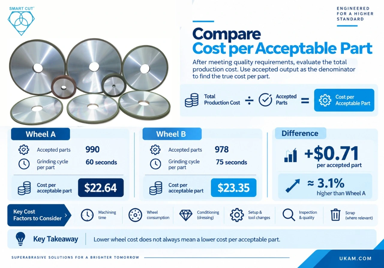
After quality requirements are met, compare total production cost. Include machining time, consumed wheel value, conditioning, setup, tool changes, inspection, rework, and scrap where they affect the decision. Use accepted output as the denominator.
This hypothetical example assumes 1,000 attempted parts for each wheel, a combined machine and labor rate of $120 per hour, and a blank cost of $20 per attempted part. Wheel cost is the amount allocated to the batch. It is not necessarily the full purchase price. Each attempted part receives the stated grinding cycle.
|
Cost or production measure |
Wheel A |
Wheel B |
|---|---|---|
|
Attempted parts |
1,000 |
1,000 |
|
Accepted parts |
990 |
978 |
|
Grinding cycle per attempted part |
60 seconds |
75 seconds |
|
Total grinding time |
1,000 minutes |
1,250 minutes |
|
Total dressing time |
36 minutes |
27 minutes |
|
Allocated setup and wheel change time |
20 minutes |
20 minutes |
|
Total machine and labor time |
1,056 minutes |
1,297 minutes |
|
Machine and labor cost |
$2,112 |
$2,594 |
|
Allocated wheel cost |
$300 |
$240 |
|
Blank cost for attempted parts |
$20,000 |
$20,000 |
|
Total included batch cost |
$22,412 |
$22,834 |
|
Cost per acceptable part |
$22.64 |
$23.35 |
Cost per acceptable part = Total included batch cost / Accepted parts
Wheel B has lower allocated wheel cost and less total dressing time. Its longer cycle and lower accepted output nevertheless produce a higher cost per acceptable part. The difference is approximately $0.71 per accepted part, or 3.1% above Wheel A in this example.
Add other material costs, inspection, rework, coolant, disposal, or downtime where relevant. Avoid counting labor twice when it is already included in the machine rate. If scrap is detected early or parts are reworked, record the actual time and cost rather than applying an unchanged full cycle to every part.
Consider a custom wheel when the requirement calls for it
A custom wheel can address a required profile, abrasive working width, diameter, mounting feature, or abrasive specification that a standard wheel does not provide. It may also help when a standard construction cannot meet the quality and production objectives within the available machine conditions.
UKAM manufactures diamond and CBN wheels in several bond constructions. We can review geometry, grit, concentration where applicable, bond, and mounting together. For an existing process, provide the current wheel drawing or specification and explain the quality or production limit you want to improve.
A complete recommendation should identify the proposed construction, the application assumptions, the required conditioning method, and the trial results needed to confirm suitability. Specify acceptance requirements with the wheel so that quality, useful life, and production performance can be evaluated consistently.
Common selection questions
Sometimes. Test whether one specification can remove the required stock and still meet the final surface and edge requirements at an acceptable cycle time. Separate stages may be more effective when those demands conflict.
Those dimensions establish only part of the requirement. Also identify the working geometry, abrasive, grit, bond, concentration where specified, mounting details, and the material being ground. A drawing or complete current specification helps avoid an unsuitable replacement.
Use existing settings as a starting point only when they suit the new construction and remain within approved limits. Record any changes so that the comparison reflects how each wheel was actually operated.
No. Grit influences material interaction and surface quality. Wheel form, mounted accuracy, workholding, deflection, thermal stability, and measurement capability also affect dimensional results.
Request a wheel recommendation for your application
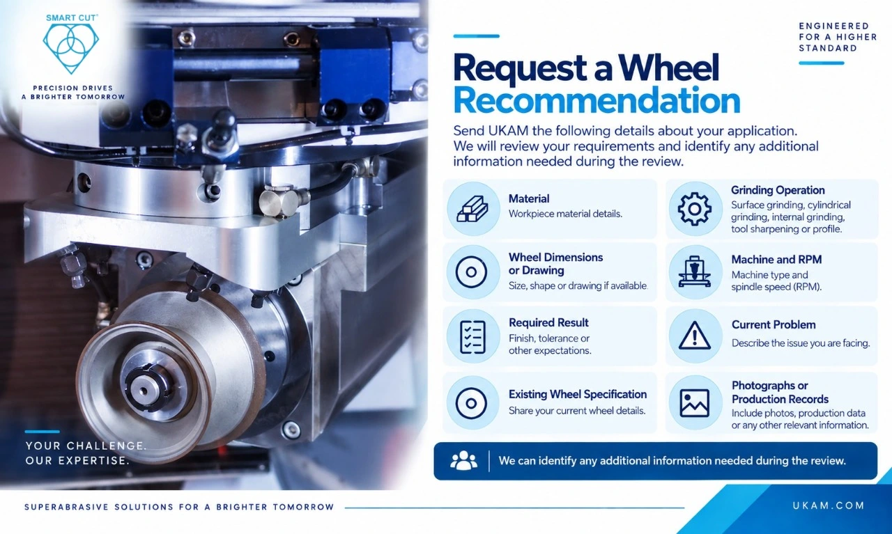
Send UKAM your material, grinding operation, wheel dimensions or drawing, machine and RPM, required result, and current problem. Include your existing wheel specification and any photographs or production records you have. We can identify additional information needed during the review.
Contact UKAM for a grinding wheel application review to discuss standard or custom wheel options for your requirements.
Trusted by Tens of Thousands of Manufacturers, Laboratories,
Research Institutions Worldwide Since 1990
American Based Manufacturer
Established in 1990
