



















How to Select a Diamond Blade for Composite Materials: Bond Selection, Cut Quality, and Cost per Part

Table of Contents
Toggle
American Based Manufacturer

Established in 1990


Custom manufacturing


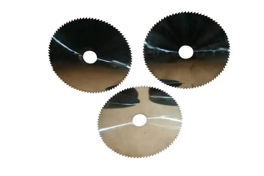
Selecting a diamond blade for composite materials requires matching the blade specification to the material, cutting geometry, machine capability, and finished-part requirements. A blade that works well on glass-fibre-reinforced polymer (GFRP) may not produce the same results on carbon-fibre-reinforced polymer (CFRP), aramid laminates, or hybrid structures.
The reason is material behaviour. Fibre type, resin system, laminate orientation, and layer construction influence cutting forces, edge damage, abrasive wear, and heat generation. These variables affect both product quality and production cost.
For manufacturing engineers, the objective is to identify a blade that meets the required tolerances and edge-quality limits while maintaining repeatable output at an acceptable cost per conforming part.
This article explains how to evaluate composite materials, compare blade constructions, diagnose cutting defects, and qualify a blade using measurable production results.
Identify the Composite Material and Cutting Requirements
Start by documenting the material and the intended cut. The term composite covers materials with different fibre structures, matrices, and cutting characteristics. Selecting a blade based only on a broad material category can lead to an unsuitable specification.
|
Material |
Potential cutting challenges |
Initial evaluation priorities |
|---|---|---|
|
Carbon-fibre-reinforced polymer (CFRP) |
Fibre breakout, delamination, matrix damage, abrasive wear |
Layup, fibre orientation, edge support, dimensional accuracy |
|
Glass-fibre-reinforced polymer (GFRP) |
Abrasive wear, edge breakout, resin damage |
Fibre content, resin system, tool wear, cutting consistency |
|
Aramid laminates |
Fibre pull-out, fraying, incomplete severing |
Edge condition, fibre architecture, support, cutting direction |
|
Honeycomb sandwich panels |
Core crushing, skin damage, irregular edges |
Face-sheet material, core structure, panel support |
|
Hybrid laminates |
Changing cutting behaviour between layers |
Layer sequence, thickness, local damage, edge consistency |
|
Particle- or ceramic-filled composites |
High abrasive loading and possible accelerated wear |
Filler composition, bond suitability, wear progression |
These are potential failure modes, not guaranteed outcomes. Actual behaviour depends on the material formulation, component construction, blade specification, and operating conditions.
Before requesting a blade, record:
- Material designation, fibre type, resin system, and laminate construction.
- Workpiece thickness and cutting geometry.
- Required kerf width, dimensional tolerances, and edge-acceptance criteria.
- Production volume and current cutting method.
- Machine type, spindle arrangement, and workholding method.
- Any restrictions on coolant, extraction, contamination, or downstream processing.
This information gives the blade manufacturer a defined application rather than a general request to cut composite material.
Match Blade Construction to the Application
Blade selection involves several interacting features: edge design, abrasive specification, bond system, blade thickness, and body stability. No single feature determines performance independently.
Edge design and blade geometry
Continuous-rim, slotted, segmented, serrated, and other edge configurations have different designs and intended applications. Their suitability must be established for the specific composite and cutting operation.
|
Feature |
Selection consideration |
What to verify |
|---|---|---|
|
Edge configuration |
Required cutting action and edge condition |
Manufacturer's application guidance and trial results |
|
Blade thickness |
Kerf requirement and dimensional stability |
Actual kerf, runout, deflection, and finished dimensions |
|
Blade diameter |
Machine compatibility and required cutting geometry |
Approved diameter, spindle limits, and available cutting depth |
|
Arbor and mounting |
Correct fit and stable blade support |
Arbor dimensions, flange arrangement, and mounting instructions |
|
Nonstandard dimensions or application requirements |
Drawing, tolerances, material details, and production objectives |
A thin blade can reduce material removal, but it does not automatically produce a more accurate cut. Runout, blade deflection, mounting, workpiece support, and machine condition must also be controlled.
Bond selection
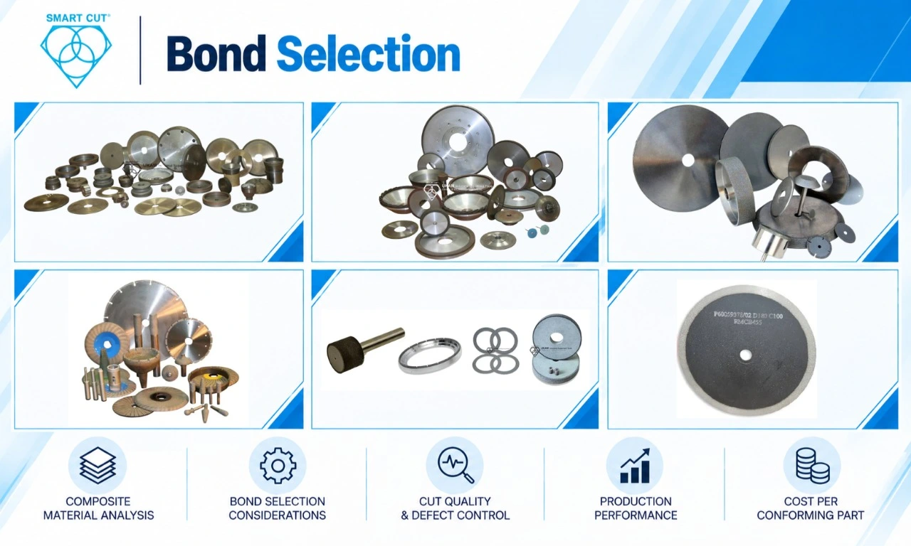
The bond retains the diamond abrasive and affects how the cutting edge wears during use. Selection should account for the material, required finish, operating conditions, and intended wear behaviour.
UKAM’s published composite-industry information lists several bond options, including sintered metal, resin, nickel, brazed, and vitrified constructions. Confirm the current availability and application suitability of the specific product before specifying it.
|
Bond family or construction |
Questions to resolve |
|---|---|
|
Is the construction suitable for the material's abrasive characteristics and required edge quality? |
|
|
Does the specific blade meet the finish, wear, and operating requirements? |
|
|
Is the abrasive-retention design appropriate for the intended operation and required usable life? |
|
|
Does the manufacturer's specified construction support the intended material and cutting conditions? |
|
|
Is this construction available and approved for the particular blade application? |
|
|
What are the actual specifications and documented application limits? |
Bond names alone do not establish cutting speed, tool life, or finish quality. Abrasive size, concentration, bond formulation, edge geometry, and process conditions also influence the result.
Diagnose Cutting Defects Using Observable Evidence
A defect may originate from the blade, machine, fixture, cutting parameters, or material variation. Identify the likely cause before changing the blade specification.
|
Observed defect |
Possible causes |
Diagnostic checks |
|---|---|---|
|
Delamination |
Inadequate support, local cutting forces, laminate orientation, unsuitable process parameters |
Inspect damage location, layup, fixture support, and cutting direction |
|
Fibre breakout or fraying |
Fibre architecture, edge condition, support, cutting direction |
Examine the defect pattern and compare controlled trials |
|
Resin smearing or thermal damage |
Excessive heat, rubbing, unsuitable speed/feed combination, ineffective cooling where required |
Review cutting behaviour, temperature-related evidence, and cooling arrangements |
|
Rising cutting force |
Blade wear, loading, runout, material variation, machine problems |
Inspect blade condition and mounting; review force or power trends if available |
|
Taper or inconsistent kerf |
Blade deflection, misalignment, runout, fixture movement |
Measure kerf at multiple locations and check alignment |
|
Premature blade damage |
Incorrect mounting, unsuitable specification, operation outside approved limits |
Inspect the blade and mounting system against manufacturer instructions |
|
Increasing cycle time |
Wear, loading, parameter drift, machine condition |
Compare cycle time and blade condition with the established baseline |
Treat these causes as diagnostic hypotheses until inspection or testing supports them.
Record the defect location, dimensions, frequency, and relevant operating conditions. For example, entry or exit damage may require a different investigation from damage distributed throughout the cut. Where internal damage is a concern, use the inspection method required by the component specification; visual examination alone may not be sufficient.
Establish Approved Cutting Parameters
Rotational speed and feed rate influence cutting behaviour, but there is no universal setting for every diamond blade and composite material. The approved range depends on the exact blade, diameter, machine, workpiece, and process requirements.
Verify the manufacturer’s operating limits before running a trial.
RPM calculation
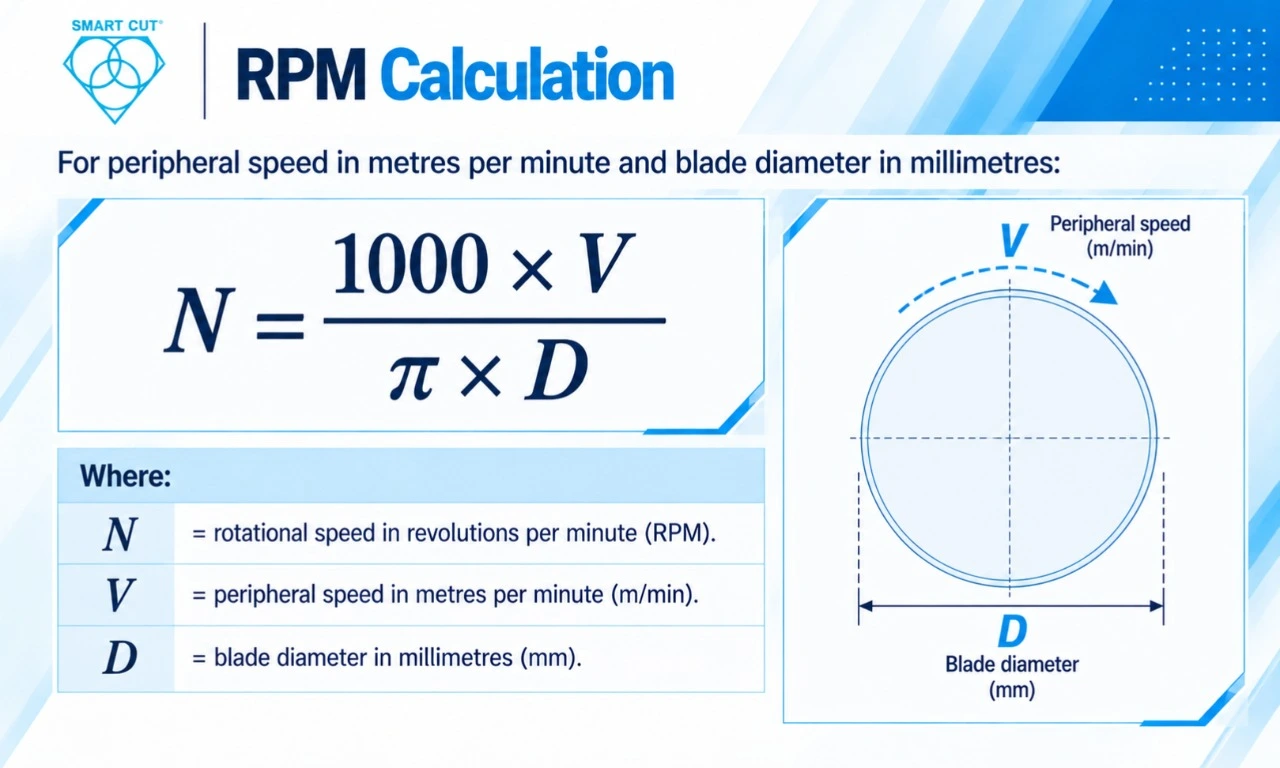
For peripheral speed V in metres per minute and blade diameter D in millimetres:
N=1000VπD
Where:
N = rotational speed in revolutions per minute.
V = peripheral speed in metres per minute.
D = blade diameter in millimetres.
Illustrative calculation, not an operating recommendation: For a 100 mm blade at an assumed peripheral speed of 20 m/min:
N=1000(20)π(100) ≈ 63.7 RPM
This example demonstrates the calculation only. The assumed speed is not a UKAM specification or a recommended operating condition.
During process development, change one principal variable at a time unless the test plan deliberately evaluates multiple factors. Keep the material, fixture, inspection method, and other relevant conditions consistent. Record actual operating conditions rather than relying solely on machine setpoints.
Stop testing if the blade, workpiece, machine, or process exhibits an unsafe or unacceptable condition.
Measure Performance Across the Production Process
A short cycle time does not necessarily indicate a successful blade selection. The evaluation must include the quality of the finished part and the resources consumed to produce it.
|
Metric |
Definition |
|---|---|
|
Cutting time |
Time required to complete the defined cut or part |
|
Kerf width |
Width of material removed, measured consistently |
|
Edge acceptance |
Proportion of inspected cuts meeting specified criteria |
|
Tool life |
Cuts, parts, or cutting distance achieved before a defined end-of-life limit |
|
Number of conditioning operations over a defined production quantity |
|
|
Rework rate |
Proportion of parts requiring additional work because of cutting-related defects |
|
Scrap rate |
Proportion of parts rejected under the specified acceptance criteria |
|
Cost per acceptable part |
Relevant production costs divided by accepted output |
Define blade end of life before testing. Suitable criteria may include dimensional drift, unacceptable edge damage, excessive cutting time, a documented wear limit, or a manufacturer-specified restriction.
Compare candidate blades under equivalent conditions and use the same inspection and end-of-life criteria. Repeat testing sufficiently to determine whether the result is consistent rather than an isolated successful cut.
Calculate Cost per Acceptable Part
Blade purchase price is only one component of production cost. A meaningful comparison should include blade consumption, machine time, incremental labour, conditioning, consumables, changeover downtime, and downstream finishing attributable to the cutting process.
The exact categories depend on the plant’s accounting method. If the machine-hour rate already includes operator labour, adjust the model to avoid counting labour twice.
Cost per attempted part:
Cattempt = Cblade + Cmachine + Clabour + Cconditioning + Cconsumables + Cchangeover + Cfinishing
Cost per acceptable part:
Cacceptable = CattemptY
Here, Y is accepted yield expressed as a decimal.
The following values are hypothetical. They are not actual UKAM prices, measured production results, supplier comparisons, or guaranteed performance outcomes.
|
Cost per attempted part |
Scenario A |
Scenario B |
|---|---|---|
|
Blade consumption |
$0.150 |
$0.130 |
|
Machine time |
$0.750 |
$0.633 |
|
Incremental operator labour |
$0.375 |
$0.317 |
|
Conditioning machine cost |
$0.020 |
$0.010 |
|
Conditioning labour |
$0.010 |
$0.005 |
|
Coolant and consumables |
$0.050 |
$0.050 |
|
Blade-change downtime allocation |
$0.004 |
$0.003 |
|
Downstream finishing |
$0.200 |
$0.100 |
|
Total cost per attempt |
$1.559 |
$1.248 |
|
Accepted yield |
95% |
98% |
|
Cost per acceptable part |
$1.641 |
$1.273 |
Calculations:
$1.2480.98 ≈ $1.273
Under these assumptions, Scenario B has a lower calculated cost per acceptable part. This is a mathematical illustration, not evidence that a particular blade or supplier will produce the same outcome.
For a production decision, replace all assumed values with measured plant data. The cost per attempt should include costs incurred across all attempts, including rejected parts. Dividing by accepted yield then expresses that cost per conforming part. Do not add a second scrap penalty for costs already included.
Qualify the Blade Before Production Release
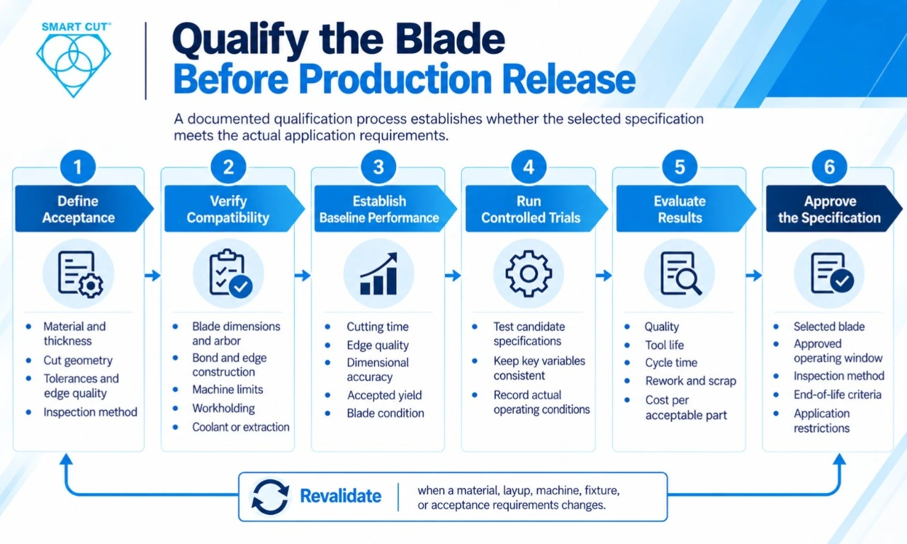
A documented qualification process establishes whether the selected specification meets the actual application requirements.
Phase 1: Define acceptance
Record the material, layup, thickness, cut geometry, dimensional tolerances, edge-quality limits, and inspection method.
Phase 2: Verify compatibility
Confirm blade dimensions, arbor, bond, edge construction, mounting, machine limits, workholding, and any coolant or extraction requirements with the manufacture
Phase 3: Establish baseline performance
Record cutting time, edge quality, dimensional accuracy, accepted yield, blade condition, and downstream finishing using the existing process.
Phase 4: Run controlled trials
Test candidate specifications under a documented plan. Keep relevant variables consistent and record the actual operating conditions.
Phase 5: Evaluate results
Compare quality, tool life, cycle time, conditioning, rework, scrap, and cost per acceptable part.
Phase 6: Approve the specification
Document the selected blade, approved operating window, inspection method, end-of-life criteria, and application restrictions.
Revalidate when a material, layup, machine, fixture, or acceptance requirement changes enough to affect cutting performance.
Application-Specific Priorities
CFRP
Evaluate fibre breakout, delamination, dimensional stability, and edge condition. Record the laminate orientation and inspect the entry, exit, and cut surfaces as required. Include suitable controls for airborne fibre dust and housekeeping.
GFRP
Track abrasive wear and changes in cutting behaviour over a defined production quantity. Compare edge damage, dimensional stability, cycle time, and the rate at which blade performance changes.
Aramid laminates
Inspect for fibre pull-out, fraying, and incomplete severing. Evaluate blade edge design alongside workpiece support and cutting direction.
Honeycomb and sandwich panels
Identify the face-sheet material, core type, adhesive system, and panel construction. Assess skin damage and core crushing separately, because different layers may respond differently to cutting forces.
Hybrid laminates
Document layer order and thickness. Inspect material transitions because cutting behaviour can change as the blade passes through different layers.
Common Selection Errors
- Choosing on price alone: Compare production cost and accepted yield, not purchase price in isolation.
- Specifying only the material category: Provide the actual material, layup, thickness, and cut requirements.
- Ignoring machine condition: Runout, mounting errors, vibration, and unstable workholding can compromise a suitable blade.
- Using inconsistent test criteria: Different inspection methods or end-of-life limits make comparisons unreliable.
- Changing several variables without a test plan: Results become difficult to interpret.
- Approving from one successful cut: Production approval requires repeatable performance under representative conditions.
- Assuming bond type predicts results: Verify the complete blade specification in the intended application.
Specifying a Composite Diamond Blade Through UKAM
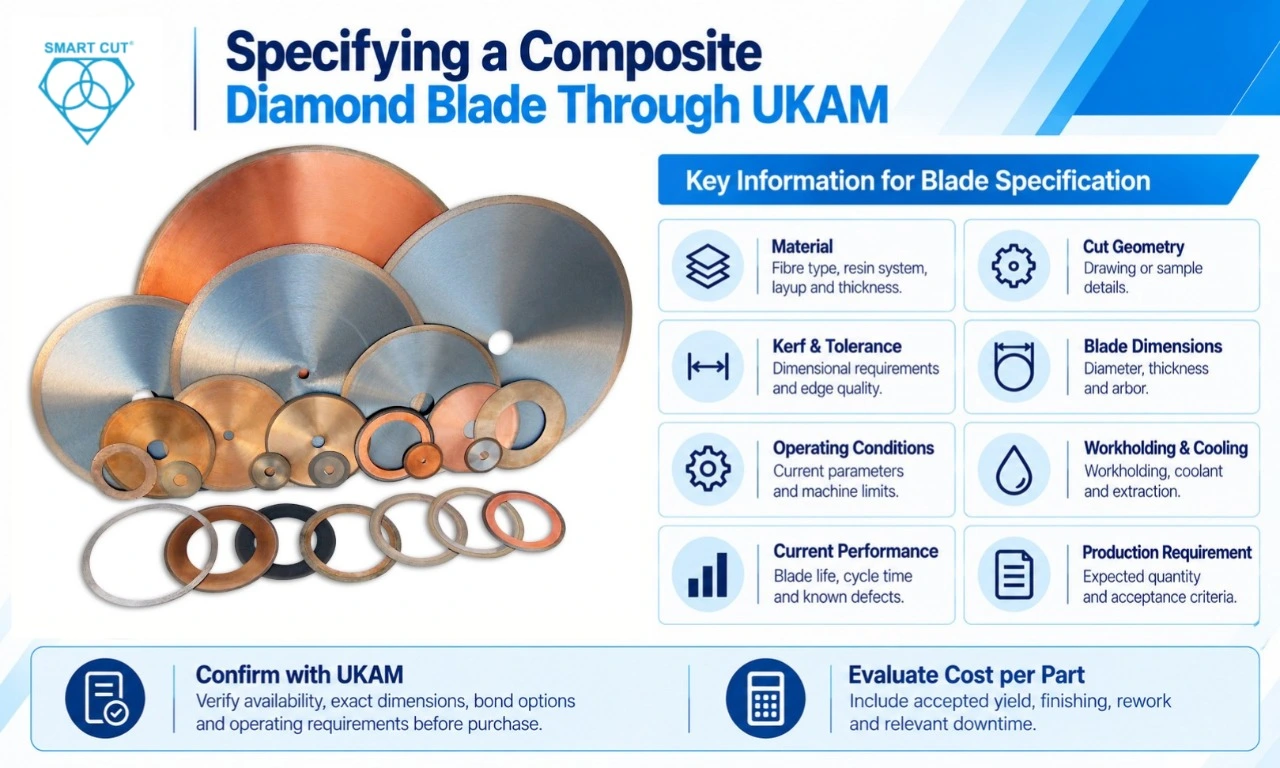
UKAM’s published Diamond Blades for Composites and Composite Industry pages describe blade solutions and applications for composite processing. The composite-industry page lists several bond options and operations such as slicing, dicing, wafering, cut-off, singulation, grooving, slotting, cross-sectioning, gang sawing, slabbing, and rough cutting.
UKAM also describes its SMART CUT® technology as a design intended to expose successive layers of abrasive as the bond matrix wears. This is the manufacturer’s description of its technology; it does not establish a specific improvement in tool life, cycle time, or yield for every composite application.
When requesting a blade specification, provide:
- Material designation, fibre type, resin system, layup, and thickness.
- Drawing or sample details and required cut geometry.
- Kerf, dimensional tolerance, and edge-acceptance criteria.
- Blade diameter, thickness, arbor, and machine details.
- Current operating parameters and applicable machine limits.
- Workholding, coolant, and extraction arrangements.
- Current blade life, cycle time, conditioning frequency, and known defects.
- Expected production quantity and acceptance criteria.
Confirm the availability, exact dimensions, bond options, and operating requirements of the proposed blade directly with UKAM before purchase or production use.
For economic evaluation, refer to UKAM’s Diamond Blade Cost per Cut resource. For composite cutting, include accepted yield, finishing, rework, and relevant downtime so the comparison reflects the cost of conforming parts.
Production Qualification Checklist
- Material, layup, and thickness documented.
- Dimensional and edge-quality criteria defined.
- Blade dimensions, bond, edge design, and mounting compatibility verified.
- Machine condition, workholding, and operating limits checked.
- Baseline performance recorded.
- Trial conditions and results documented.
- Dimensional accuracy and edge damage inspected.
- Tool-life and end-of-life criteria defined.
- Accepted yield, rework, scrap, and finishing recorded.
- Cost per acceptable part calculated without double-counting.
- Repeatability demonstrated under representative conditions.
- Approved blade specification and operating window documented.
Frequently Asked Questions
There is no single best specification for all composites. The choice depends on fibre type, resin, laminate construction, cutting geometry, machine capability, and edge-quality requirements. Validate the proposed blade using representative material and defined acceptance criteria.
Diamond blades are offered for various composite-cutting applications, including carbon-fibre and glass-fibre composites. Suitability depends on the exact blade and process. Confirm the application with the manufacturer and evaluate the actual material before production release.
Bond suitability depends on the material, abrasive loading, required finish, operating conditions, and wear behaviour. Review the exact blade specification with the manufacturer rather than choosing from the bond name alone.
Inspect the damage pattern and review laminate orientation, workpiece support, cutting direction, blade condition, machine alignment, and process parameters. Test changes systematically and verify the result against the required acceptance criteria.
Define end of life using a measurable condition, such as unacceptable dimensional drift, edge damage, wear, cutting time, or a manufacturer-specified limit. Record the number of cuts or accepted parts produced under documented conditions.
No. Compare blade consumption, machine time, conditioning, downtime, finishing, rework, and accepted yield using the same accounting method for each candidate.
Only after confirming that the materials and cutting requirements are sufficiently similar. Changes in fibre type, resin, layer orientation, thickness, or core structure may require additional qualification.
Provide the material designation, layup, thickness, cut geometry, tolerances, edge requirements, machine and mounting details, operating conditions, current defects, and expected production volume.
Conclusion
Selecting a diamond blade for composite materials requires matching blade construction to the material and validating the complete cutting process. The strongest specification is the one that repeatedly meets dimensional and edge-quality requirements at an acceptable cost per conforming part.
Document the application, verify compatibility, run controlled trials, and compare results using consistent inspection and cost criteria. Use measured production evidence to approve the final specification rather than relying on purchase price, generic bond recommendations, or a single successful cut.
For application-specific guidance, review UKAM’s Diamond Blades for Composites and Composite Industry resources, then confirm the proposed blade specification with the manufacturer before production use.
American Based Manufacturer
Established in 1990
