


Common Causes of Thermal Damage During PCD Grinding Operations
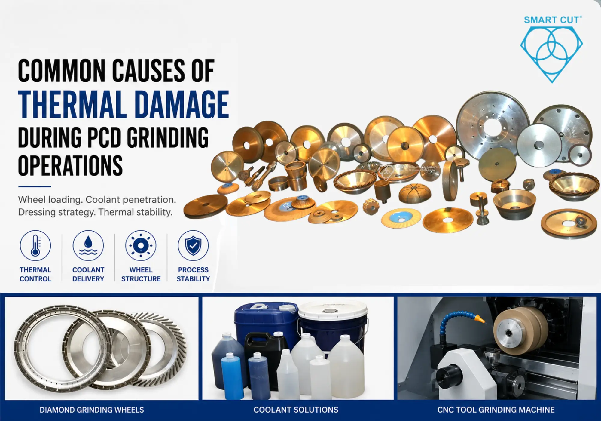
Table of Contents
Toggle
American Based Manufacturer

Established in 1990


Custom manufacturing


A manufacturer producing PCD cutting tools for aerospace aluminum machining and composite machining applications experienced recurring thermal damage during finish grinding operations. Operators reported edge discoloration, unstable wheel wear, inconsistent edge radius formation, surface haze, and premature insert failure during production validation.
The grinding process initially produced acceptable edge quality during low-volume production runs. Problems intensified during continuous operation as wheel loading increased and coolant penetration near the grinding interface became unstable. Several inserts passed dimensional inspection but failed during customer machining trials because thermal stress weakened the diamond-carbide interface.
The original process used a dense metal bond diamond grinding wheel selected primarily for wheel retention and dimensional stability. Coolant delivery remained inconsistent near the grinding contact zone during long grinding passes. Dressing intervals varied between operators and abrasive exposure deteriorated progressively during production.
Initial troubleshooting focused on reducing spindle RPM and lowering feed pressure. Grinding temperature decreased slightly but thermal damage continued because wheel loading and grinding force remained unstable. Process qualification confirmed that wheel porosity, bond structure, coolant penetration, and dressing consistency influenced thermal stability more significantly than RPM reduction alone.
A revised grinding process using a vitrified bond diamond grinding wheel, improved coolant delivery, and controlled dressing intervals stabilized grinding temperatures while improving edge consistency and reducing production scrap. Explore UKAM’s PCD Grinding Solutions engineered for these applications.
Customer Application and Manufacturing Environment
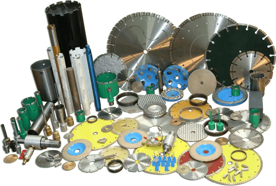
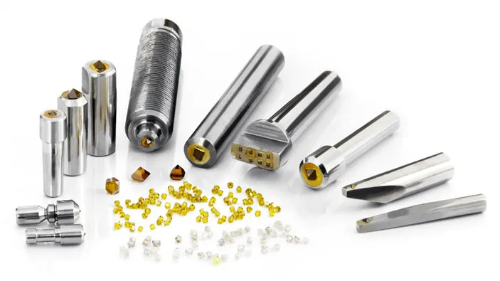
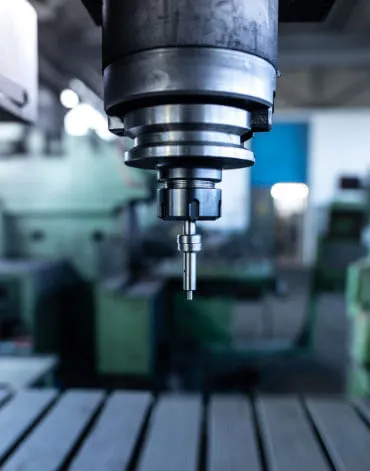
The components were PCD cutting inserts used for machining aluminum alloys, CFRP composites, high-silicon automotive materials, and aerospace structural components. Grinding operations included peripheral grinding, relief grinding, edge preparation, and finish polishing on CNC grinding systems used in precision tooling environments. UKAM’s PCD Tool Manufacturing Applications cover this full range of operations.
Production Environment
|
Parameter |
Original Production Setup |
|---|---|
|
Material |
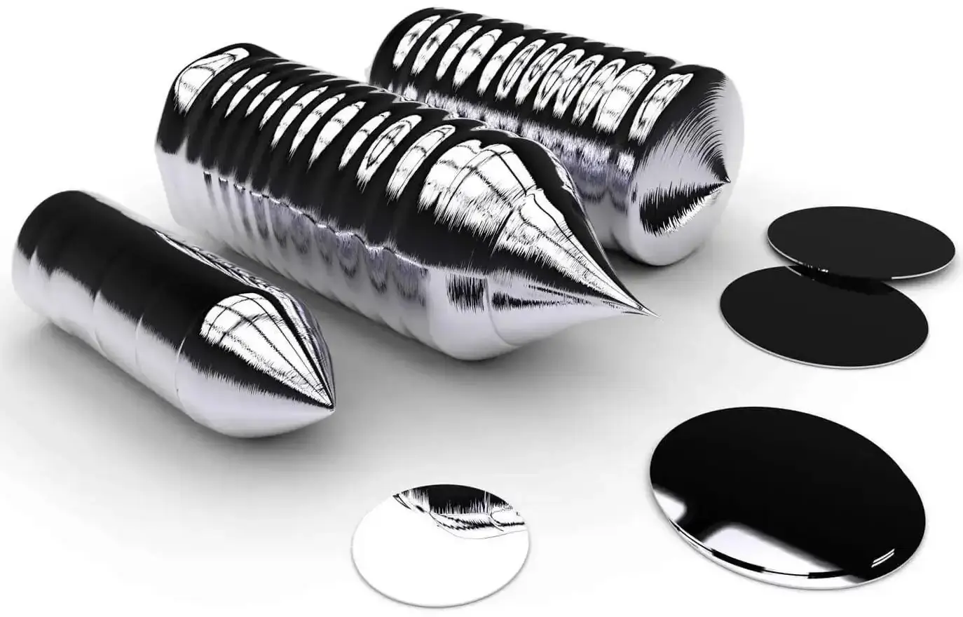
PCD on tungsten carbide substrate |
|
Industry |
Aerospace and precision tooling |
|
Machine type |
CNC PCD grinding machine |
|
Grinding wheel |
Metal bond diamond wheel |
|
Coolant system |
Flood coolant |
|
Operation |
Finish grinding and edge preparation |
|
Primary issue |
Thermal damage and wheel loading |
|
Surface finish requirement |
Precision edge preparation |
|
Grinding challenge |
Stable thermal control during long grinding cycles |
The grinding process became unstable during extended production cycles because wheel exposure deteriorated progressively while coolant penetration at the wheel-workpiece interface remained inconsistent.
Why Thermal Damage Develops During PCD Grinding

PCD grinding behaves differently than grinding tungsten carbide, alumina, silicon carbide, sapphire, or fused silica. Polycrystalline diamond materials combine extremely high hardness with complex thermal behavior at the diamond-carbide interface.
Heat accumulation during grinding affects both the diamond structure and the cobalt binder phase within the PCD layer. Excessive thermal loading weakens the interface and accelerates edge fracture during cutting operations.
Material Behavior During Grinding
|
Material |
Grinding Difficulty |
Thermal Sensitivity |
Primary Failure Mode |
|---|---|---|---|
|
PCD |
Very high |
Very high |
Thermal edge degradation |
|
Tungsten Carbide |
High |
Moderate |
Surface micro cracking |
| Silicon Carbide |
Very high |
Moderate |
Wheel loading |
|
Alumina |
High |
High |
Edge chipping |
|
Sapphire |
Very high |
Very high |
Subsurface fracture |
|
CBN materials |
High |
Moderate |
Thermal edge wear |
The original dense metal bond wheel retained worn abrasive particles aggressively. Grinding force increased progressively once abrasive exposure deteriorated, concentrating heat at the grinding interface. See UKAM’s full range of Diamond Grinding Wheel Solutions for advanced materials.
Existing Process Problems
The original grinding setup maintained dimensional control but generated unstable thermal conditions during finish grinding operations.
Thermal Failure Indicators
|
Observation |
Root Cause |
|---|---|
|
Surface discoloration |
Excess grinding temperature |
|
Cobalt leaching |
Thermal degradation |
|
Edge micro fracturing |
Localized thermal stress |
|
Increased spindle load |
Wheel loading |
|
Surface haze |
Dull abrasive exposure |
|
Frequent dressing requirements |
Poor self-sharpening behavior |
|
Edge radius inconsistency |
Grinding instability |
Operators attempted to compensate by lowering feed pressure, which reduced throughput but failed to stabilize thermal behavior.
Cost Per Part Analysis: Metal Bond vs Vitrified Bond Grinding Process

Process Comparison
The primary production improvement came from stabilizing grinding force and reducing thermal accumulation rather than maximizing wheel retention alone.
Grinding Wheel Qualification Trials
|
Parameter |
Conventional Metal Bond Process |
Vitrified Bond Grinding Process |
|---|---|---|
|
Wheel retention |
Higher |
Controlled |
|
Grinding temperature stability |
Variable |
More stable |
|
Dressing frequency |
More frequent |
Reduced |
|
Reduced |
Reduced |
Reduced |
|
Wheel loading tendency |
Higher |
Lower |
|
Surface finish consistency |
Variable |
Improved |
|
Production interruption frequency |
Higher |
Lower |
|
Long-term process stability |
Moderate |
Improved |
The engineering team evaluated multiple wheel specifications during production qualification testing.
Qualification Matrix
|
Wheel Configuration |
Bond Type |
Result |
|---|---|---|
|
Wheel A |
Dense metal bond |
Stable form retention, high thermal loading |
|
Wheel B |
Resin bond |
Lower heat generation, moderate wheel wear |
|
Wheel C |
Vitrified bond |
Best thermal stability and wheel consistency |
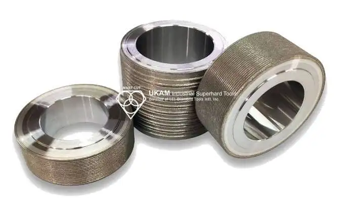
Wheel C generated the most stable grinding force because the vitrified structure allowed controlled abrasive release while maintaining coolant access through engineered porosity. Explore UKAM’s Vitrified Bond Diamond Grinding Wheels for PCD and advanced material applications.
The qualification trials also confirmed that wheel porosity affected thermal behavior more significantly than spindle RPM alone.
Why RPM Reduction Failed to Eliminate Thermal Damage
The production team initially attempted to reduce thermal damage by lowering spindle RPM while maintaining the original metal bond wheel specification. The approach reduced grinding temperature slightly but failed to stabilize abrasive exposure. Grinding force continued increasing because the wheel loaded progressively during extended grinding cycles.
Root Cause Evaluation
|
Attempted Correction |
Result |
Why It Failed |
|---|---|---|
|
Lower spindle RPM |
Minor improvement |
Wheel loading remained |
|
Reduced feed pressure |
Better edge quality |
Throughput reduction unacceptable |
|
Increased coolant flow |
Moderate improvement |
Interface cooling inconsistent |
|
More frequent dressing |
Improved stability |
Wheel structure still incorrect |
|
Vitrified bond wheel |
Major improvement |
Lower spindle RPMStable abrasive exposure and coolant access |
The qualification process confirmed that wheel structure and coolant penetration influenced thermal damage more significantly than RPM reduction alone. Learn more about UKAM’s SMART CUT® Technology used in vitrified bond wheel formulations.
Technical Explanation: Why the Vitrified Bond Wheel Worked
The vitrified bond wheel used an engineered porous structure that improved coolant penetration and stabilized abrasive exposure during grinding.
Unlike dense metal bond structures, the vitrified matrix released worn abrasive particles more consistently while maintaining open coolant channels near the grinding interface.
Bond Behavior Comparison
|
Parameter |
Metal Bond Wheel |
Vitrified Bond Wheel |
|---|---|---|
|
Abrasive retention |
Very high |
Controlled |
|
Coolant penetration |
Limited |
Improved |
|
Wheel loading tendency |
High |
Lower |
|
Thermal stability |
Variable |
Stable |
|
Dressing frequency |
Frequent |
Reduced |
|
Surface finish consistency |
Moderate |
Improved |
Thermal accumulation decreased because grinding force remained more stable throughout long production runs. For resin bond alternatives, see UKAM’s Resin Bond Diamond Wheels.
Coolant Delivery Optimization

The original flood coolant system delivered sufficient coolant volume but inconsistent interface cooling during finish grinding operations.
The revised grinding process repositioned coolant nozzles closer to the wheel-workpiece contact zone and improved pressure stability.
Coolant Optimization Results
|
Coolant Parameter |
Original Setup |
Optimized Setup |
|---|---|---|
|
Delivery type |
Flood coolant |
Directed interface flow |
|
Pressure stability |
Variable |
Stable |
|
Interface penetration |
Moderate |
Improved |
|
Wheel cleaning efficiency |
Inconsistent |
Stable |
|
Thermal edge damage tendency |
Higher |
Reduced |
Improved coolant penetration reduced localized heat accumulation and stabilized wheel loading during extended production cycles.
Material Specific Grinding Recommendations
Different advanced materials require different wheel structures and grinding behavior. Attempting to standardize one grinding wheel specification across multiple advanced materials usually increases thermal instability and grinding cost. UKAM offers material-specific solutions including CBN Grinding Wheels for CBN and hardened steel applications.
Material and Grinding Selection Matrix
|
Material |
Recommended Bond Type |
Failure Mode to Watch |
|---|---|---|
|
PCD |
Vitrified bond |
Thermal edge degradation |
|
Tungsten Carbide |
Resin or vitrified bond |
Surface micro cracking |
|
Silicon Carbide |
Soft vitrified bond |
Wheel loading |
|
Sapphire |
Fine vitrified bond |
Subsurface fracture |
|
Alumina |
Resin bond |
Edge chipping |
|
CBN materials |
Controlled vitrified bond |
Thermal edge wear |
Dressing Optimization During PCD Grinding
Wheel dressing intervals affected grinding temperature significantly during qualification testing. Proper dressing tooling is critical for consistent results. See UKAM’s Diamond Dressing Tools for precision wheel preparation.
Dressing Comparison
|
Dressing Method |
Grinding Stability |
Thermal Performance |
|---|---|---|
|
Infrequent dressing |
Variable |
Poor |
|
Fixed dress intervals |
Improved |
Moderate |
|
Load-based dressing strategy |
Stable |
Best |
Load-based dressing produced the most stable edge quality because wheel exposure remained consistent throughout production.
Supplier Evaluation
|
Question |
What the Answer Reveals |
|---|---|
|
What bond structure is recommended for finish grinding PCD? |
Process engineering capability |
|
What dressing interval is recommended and why? |
Abrasive exposure understanding |
|
What coolant pressure range is recommended? |
Thermal management expertise |
|
What porosity structure is used in the wheel? |
Grinding process knowledge |
|
What spindle parameters were used during qualification? |
Production validation capability |
|
Can separate wheels be recommended for rough and finish grinding? |
Real manufacturing experience |
Suppliers focused only on wheel dimensions and pricing rarely provide stable process optimization support for precision PCD grinding operations.
SMART CUT Process Comparison
|
Parameter |
Conventional Metal Bond Process |
Vitrified Bond Grinding Process |
|---|---|---|
|
Wheel retention |
Higher |
Controlled |
|
Grinding temperature stability |
Variable |
More stable |
|
Dressing frequency |
More frequent |
Reduced |
|
Reduced |
Reduced |
Reduced |
|
Wheel loading tendency |
Higher |
Lower |
|
Surface finish consistency |
Variable |
Improved |
|
Production interruption frequency |
Higher |
Lower |
|
Long-term process stability |
Moderate |
Improved |
The qualification process showed that stable abrasive exposure and improved coolant penetration reduced thermal damage more effectively than RPM reduction alone. For precision grinding machine recommendations, see UKAM’s Precision Grinding Machines.
Qualification Checklist
Machine Condition
- Verify spindle runout before finish grinding
- Confirm machine rigidity during edge preparation
- Inspect spindle bearing condition
- Verify spindle speed stability
Coolant System
- Measure coolant pressure at grinding interface
- Verify nozzle positioning
- Inspect coolant filtration condition
- Monitor coolant flow stability
Wheel Qualification
- Verify wheel balance certification
- Confirm bond specification
- Record spindle load trends
- Validate dressing interval consistency
Process Parameters
- Record rough and finish feed rates separately
- Monitor thermal discoloration
- Track surface finish variation
- Record scrap trends by production batch
Frequently Asked Questions
The dense metal bond retained worn abrasive particles too aggressively. Grinding force increased progressively as wheel loading developed, concentrating heat at the grinding interface and damaging the PCD structure.
The vitrified structure provided controlled abrasive release and improved coolant penetration through engineered porosity. Grinding force remained more stable throughout long production cycles.
Lower spindle speed reduced heat generation slightly but failed to correct wheel loading behavior. Grinding force continued increasing because abrasive exposure remained unstable.
Flood coolant volume alone does not stabilize grinding temperature. Coolant must penetrate directly into the wheel-workpiece interface to evacuate heat effectively during finish grinding operations.
Spindle load trends revealed wheel loading before visible edge degradation appeared. Load-based dressing maintained stable abrasive exposure and reduced thermal instability during production.
PCD materials contain both diamond structure and cobalt binder phases. Excessive heat weakens the interface and accelerates edge degradation during cutting operations.
The largest improvement came from stabilizing grinding force through vitrified bond wheel structure, improved coolant penetration, controlled dressing intervals, and lower wheel loading.
Key Engineering Principles
- Thermal damage during PCD grinding is primarily a grinding force and wheel loading problem.
- Dense wheel structures restrict coolant penetration during finish grinding.
- Vitrified bond wheels stabilize abrasive exposure through controlled self-sharpening behavior.
- Coolant delivery at the grinding interface affects thermal stability directly.
- Spindle load monitoring provides early warning of wheel instability.
- Dressing intervals should be based on grinding load trends rather than visual inspection alone.
- Stable PCD grinding requires balancing wheel structure, coolant delivery, machine rigidity, and feed pressure together.
- Scrap reduction often produces greater manufacturing savings than maximizing wheel retention alone.
- Different advanced materials require different grinding wheel optimization strategies.
- Precision PCD grinding processes should be qualified separately for rough and finish grinding operations.
Trusted by Tens of Thousands of Manufacturers, Laboratories,
Research Institutions Worldwide Since 1990
American Based Manufacturer
Established in 1990
Custom manufacturing
RELATED ARTICLES