Precision Sectioning of Coated, Composite, and Multilayer Materials

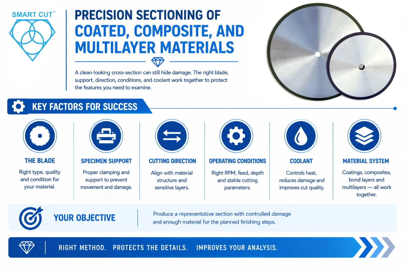
Table of Contents
ToggleA cross-section can appear straight and clean while containing damage that makes the analysis unreliable. A coating may separate from its substrate. Fibers may pull out of a polymer matrix. A thin bond layer may smear, crack, or disappear during preparation. These defects can change what you measure and how you interpret the original component.
Precision sectioning of multilayer materials requires control of the complete material system. The blade, specimen support, cutting direction, operating conditions, and coolant must work together to preserve the region you intend to examine. A process that cuts the substrate efficiently may still damage a fragile coating or weak interface.
This guide explains how to plan sectioning for coated components, reinforced composites, bonded assemblies, and layered electronic materials. The approach applies to optical microscopy, scanning electron microscopy, dimensional inspection, and failure analysis. The required preparation quality depends on the feature being investigated and the sensitivity of the measurement.
Your objective is to produce a representative section with controlled damage and enough material remaining for the planned finishing steps. Establish the method on representative material whenever possible before cutting an irreplaceable specimen.
Trusted by Tens of Thousands of Manufacturers, Laboratories Research Institutions Worldwide Since 1990

American Based Manufacturer

Established in 1990


Custom manufacturing


Start with the inspection objective
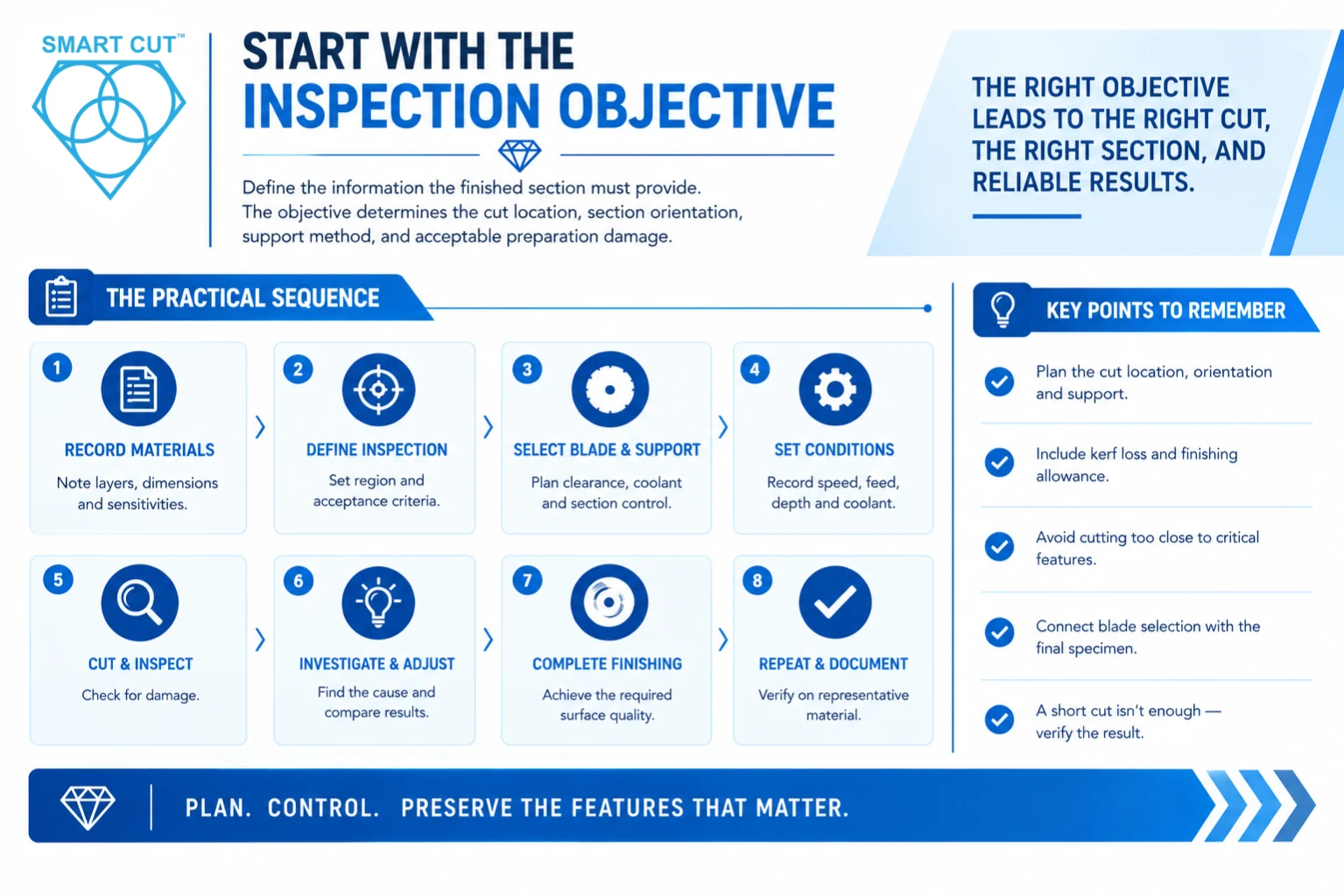
Define the information the finished section must provide. Measuring coating thickness requires a different inspection plan from locating a crack origin, assessing fiber orientation, or examining a thin adhesive bond. The measurement objective determines the cut location, section orientation, support method, and acceptable preparation damage.
Identify the region of interest before choosing a blade. Record its position relative to visible features, specimen edges, and reference surfaces. Decide how much material can be removed during sectioning and later grinding. Include kerf loss and finishing allowance in this decision. A cut placed too close to a critical feature can remove evidence that cannot be recovered.
For a new application, use this practical sequence:
- Record the constituent materials, layer thicknesses, specimen dimensions, and known sensitivities. Include coatings, adhesives, reinforcement, and any protective mounting material that the blade will contact.
- Define the inspection region and acceptance criteria. State how chipping, delamination, smearing, geometry, and other relevant features will be evaluated.
- Select a compatible blade and specimen support method. Plan blade clearance, coolant access, and control of the retained section and offcut.
- Establish starting conditions from the blade and machine recommendations. Record spindle speed, feed mode, cutting depth, coolant, and blade condition.
- Cut representative material and inspect the as-cut surfaces. Photograph the interface and record where any damage occurs.
- Investigate the most likely cause before changing the process. Make a controlled adjustment and compare the result under the same inspection conditions.
- Complete the intended grinding and polishing sequence. Confirm that the final section satisfies the analytical requirement.
- Repeat the successful procedure on representative material. Document its verified operating conditions and the changes that require reevaluation.
This sequence connects blade selection with the condition of the final specimen. A short cutting cycle has limited value if it creates damage that requires extensive rework or prevents a reliable measurement.
Understand the material stack and its damage mechanisms
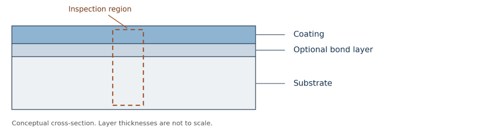
A coated specimen may combine a brittle surface layer, an intermediate bond layer, and a ductile substrate. A laminate may contain several reinforcement orientations separated by matrix-rich regions. An electronic package may contain hard, brittle, soft, and metallic constituents within a small cutting area.
These materials differ in hardness, fracture behavior, stiffness, thermal response, and resistance to material removal. The blade may contact several constituents simultaneously along its engagement arc. The process therefore involves both transitions between materials and interaction with multiple materials during the same stage of the cut.
Record the complete architecture. The thickest layer often contributes substantially to the cutting load, while a thin or weak interface may determine whether the section is acceptable. Neither material hardness nor coating thickness alone provides a sufficient basis for blade selection.
Delamination, debonding, and interface cracks
Delamination is separation between layers. Debonding can occur at a coating, adhesive, fiber, or other constituent boundary. Cutting forces, specimen flexure, vibration, and heat can initiate these defects or extend damage that already exists.
A crack following an interface does not establish its origin. The interface may have been weak before cutting, or preparation may have created or enlarged the separation. Record the observation without assigning a cause until the preparation history and supporting evidence have been considered.
Chipping, pullout, and smearing
Brittle constituents can chip near an unsupported edge or cut exit. Reinforcing fibers or particles can break away from their matrix. Ductile metals and some polymer matrices can smear across adjacent features. These effects can alter the apparent boundary between layers or obscure small voids and cracks.
Damage location is useful evidence. Breakout concentrated at the final exit suggests a different investigation from defects distributed across the entire cut. Record whether damage follows a particular layer, reinforcement direction, support boundary, or stage of blade engagement.
Thermal and geometric effects
Local heating can affect temperature-sensitive constituents and contribute to interface stress. Blade deflection, specimen movement, or an incorrectly oriented section can also distort the apparent geometry. Evaluate thermal condition and section alignment separately from surface appearance. A smooth surface can still be unsuitable for the intended measurement.
Support the specimen before cutting
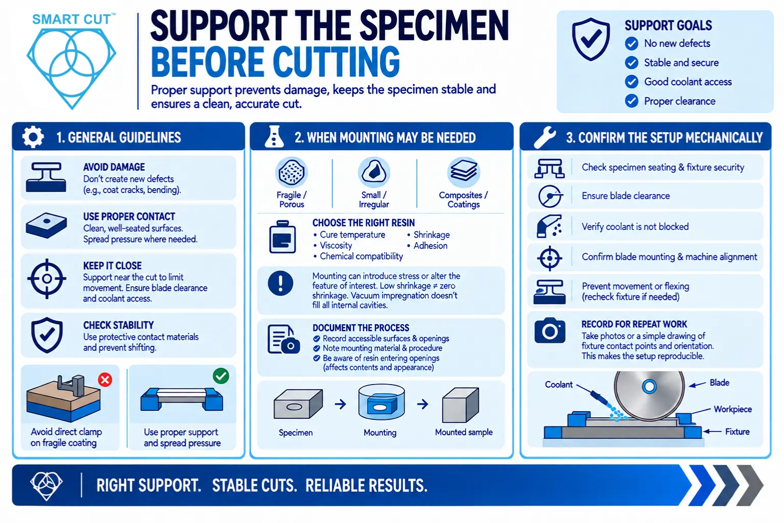
Workholding must restrain the specimen without creating the defect you are trying to investigate. A clamp placed directly on a fragile coating can introduce cracks before the blade enters. Concentrated force on a thin laminate can bend it or load an adhesive interface.
Use clean, well-seated contact surfaces and an arrangement suited to the specimen geometry. Spread contact pressure where appropriate. Keep support close enough to the cut to limit movement while maintaining blade clearance and coolant access. Check that protective contact materials provide stable restraint and do not allow the specimen to shift.
Plan support for the retained specimen and the offcut. As the remaining ligament becomes smaller, an unsupported portion may bend or break away. Conversely, a poorly planned fixture can constrain the parts in a way that closes the kerf and pinches the blade. Confirm clearance and the intended movement of each portion before the trial.
When mounting may be needed
Fragile, small, irregular, or porous specimens may require mounting before sectioning. A suitable mounting resin can support delicate edges and make the assembly easier to position. For some porous coatings and composites, vacuum impregnation can reinforce accessible pores and openings before cutting.
Select the resin for the specimen and analytical method. Consider cure temperature, shrinkage, viscosity, adhesion, and chemical compatibility. A mounting process can itself introduce stress or alter the feature of interest. Low shrinkage does not mean zero shrinkage, and vacuum impregnation does not fill every sealed internal cavity.
Where evidence preservation is critical, document accessible surfaces and existing openings before applying resin. Record the mounting material and procedure. Resin entering an opening changes its contents and appearance, so the analyst must know that impregnation occurred. Obtain an appropriate preparation method when the inspection depends on the original chemistry or contents of that opening.
Confirm the setup mechanically
Check specimen seating, fixture security, blade clearance, and the intended cut position. Confirm that the fixture does not obstruct the coolant stream. Verify blade mounting and machine alignment according to the equipment instructions. If the fixture moves or the specimen visibly flexes, correct that condition before attempting to compensate with a different feed setting.
For repeated work, record fixture contact locations and orientation with a simple photograph or setup drawing. A reproducible support arrangement is part of the cutting procedure.
Select the blade for the complete material system
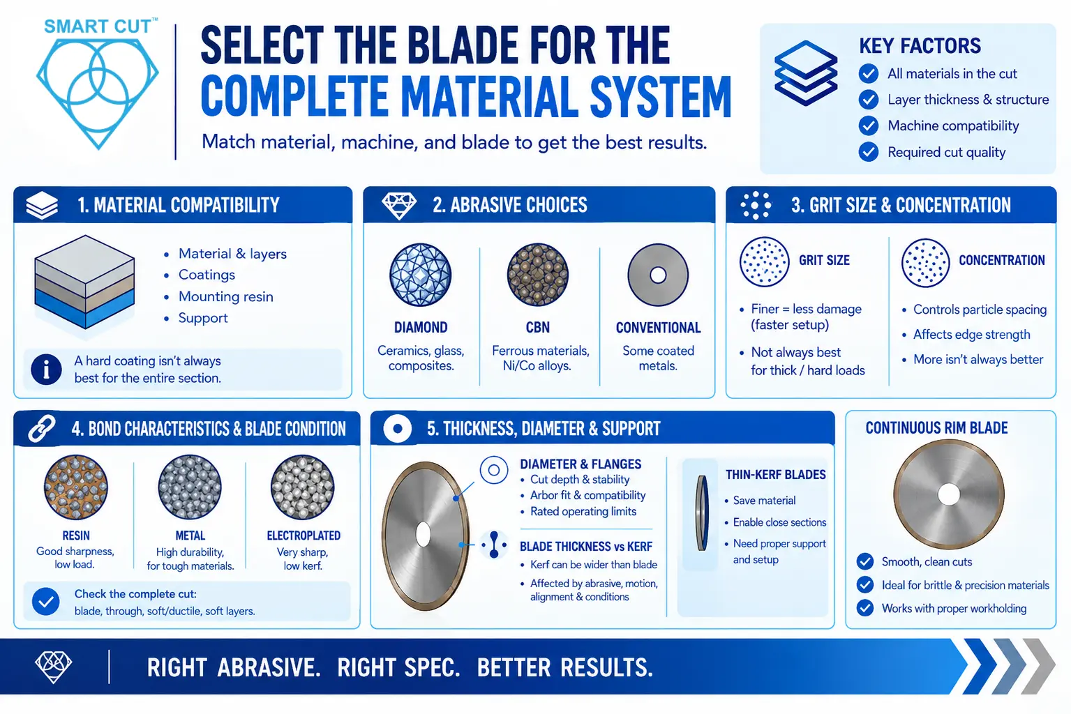
Begin with abrasive compatibility, then evaluate grit size, concentration, bond characteristics, and blade geometry. Include every material encountered during the cut. Mounting resin, metal backing, or a protective support layer can change blade loading and debris removal even when it is not the primary inspection target.
Diamond, CBN, and other abrasive choices
Diamond blades are widely used for precision sectioning of ceramics, glass, hard coatings, and many composites. Their suitability for a layered specimen still depends on the substrate and other constituents. A hard surface coating does not automatically make diamond the preferred abrasive for the entire section.
CBN may be appropriate for certain ferrous materials and nickel- or cobalt-based alloys. Conventional abrasive wheels may also be suitable for some coated metallic components. Evaluate the material combination, relative layer thicknesses, required cut quality, and machine compatibility. A mixed ceramic and metallic stack requires application-specific selection rather than a rule based on one constituent.
Grit size and concentration
Grit size affects the interaction between individual abrasive particles and the workpiece. A finer abrasive may help control surface damage in an appropriate setup, but the finest available grit is not automatically the best choice for a thick or loading-prone stack. Debris clearance, cutting resistance, and sustained cutting ability also matter.
Concentration influences the number and spacing of abrasive particles within the cutting structure. Its effect depends on the grit, bond, material, and operating conditions. Higher concentration is not a universal improvement. The useful specification is the one that maintains cutting ability while meeting the interface damage requirement.
Bond characteristics and blade condition
The bond must retain abrasive while allowing the cutting surface to remain effective. Different bond constructions provide different wear, conditioning, and material removal behavior. Resin, metal, and electroplated constructions should be evaluated against the actual stack and required blade geometry.
A blade that performs acceptably through a brittle layer may load when it reaches a ductile metal or polymer. A specification that remains sharp through the substrate may produce excessive damage in a fragile coating. Observe the complete cut and the blade condition after cutting. Judge the combination by its repeatable performance through the full assembly.
Thickness, diameter, and support
Thin-kerf blades preserve valuable material and can help produce closely spaced sections. Their selection must account for stiffness, cutting depth, workpiece support, machine condition, and required straightness. Blade diameter and flange arrangement also affect the supported and exposed portions of the blade.
Distinguish blade thickness from measured kerf. Actual kerf can differ because of abrasive projection, blade motion, alignment, and cutting conditions. When material conservation is important, verify the cut width under the intended setup and include sufficient allowance for subsequent preparation.
Select blade diameter and flange support to provide the required cut depth and stability within the equipment instructions. Confirm arbor fit, flange compatibility, usable depth, and the blade’s rated operating limits. The UKAM diamond and CBN wafering blade guide provides additional background on these selection variables.
Plan cutting direction, entry, and exit
Document specimen orientation relative to blade rotation, feed direction, layers, and reinforcement. A note stating only that the sample was cut vertically is insufficient if the next operator cannot reproduce which surface the abrasive entered and where it exited.
For some brittle coatings, orienting the cutting action into the coating toward the supporting substrate can help reduce separation caused by outward drag. Treat this as a starting consideration for suitable coated systems. Confirm the direction through representative trials, because reinforcement architecture, geometry, fixture support, and blade engagement change the result.
In composites, record the fiber or ply orientation relative to the section plane. Longitudinal fibers, transverse fibers, and woven reinforcement can respond differently. A process verified in one orientation should not automatically be accepted for another.
Pay particular attention to the final exit. Support and engagement change as the remaining material becomes thinner. If damage occurs mainly at exit, investigate the unsupported length, offcut control, cutting direction, and feed behavior at that stage. A localized exit problem may not require changing the blade specification used successfully through the rest of the sample.
When comparing orientations, keep the remaining conditions as consistent as practical. Photograph the arrangement so that an apparent improvement can be connected to an identifiable setup change.
Establish speed, feed, and blade condition together
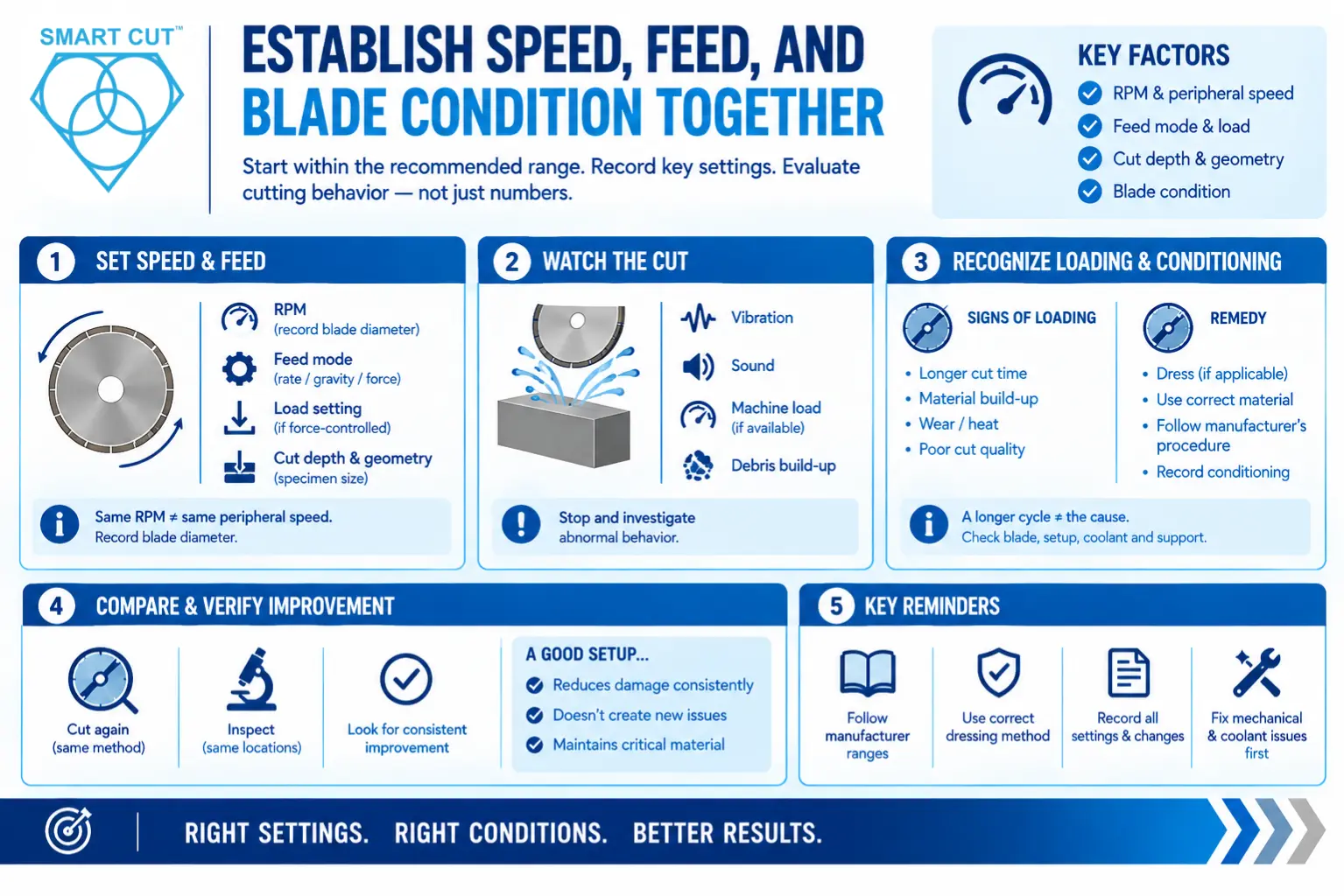
Start within the blade and machine manufacturer’s recommended operating range. Record blade diameter as well as RPM. The same RPM produces a different peripheral speed when blade diameter changes, so RPM alone does not describe equivalent conditions across machines or blade sizes.
Document the feed mode. A programmed feed rate, gravity feed, and force-controlled feed are different operating conditions. For systems that apply force rather than a fixed advance rate, record the applicable load setting and observe the actual cutting behavior. Also record cut depth and specimen geometry, because engagement changes as the blade progresses.
A conservative trial means using a controlled, appropriate starting condition. It does not mean selecting the lowest possible RPM or feed. Arbitrary reductions can change cutting behavior without correcting poor support, loading, or an unsuitable blade. Evaluate force, heat, cut quality, and cutting time together.
During each trial, observe unusual vibration, changes in sound, stalled progress, machine load where available, and debris accumulation. Stop and investigate abnormal behavior before continuing with a valuable specimen. Correct mechanical instability and inadequate coolant delivery before attempting to optimize the cutting rate.
Recognize loading and conditioning needs
If cutting time increases under otherwise similar conditions, inspect the blade and setup. Accumulated material on the cutting edge can reduce cutting ability. Wear, changing engagement, coolant restriction, or specimen movement can produce similar symptoms, so a longer cycle alone does not identify the cause.
Where the blade construction permits dressing, follow the recommended dressing material and procedure. Do not apply a dressing method intended for a multilayer abrasive rim to a different construction without confirmation. Record conditioning before comparative trials, because a freshly conditioned blade and a loaded blade are not equivalent starting conditions.
After an adjustment, make a comparable cut and inspect the same locations using the same method. A useful improvement reduces the relevant damage consistently without creating another unacceptable condition, such as excessive cut deviation or loss of critical material.
Control coolant compatibility, delivery, and cleanliness
Coolant must reach the blade and workpiece contact region throughout the operation. Check access at full cutting depth, not only at initial entry. Clamps, mounting blocks, specimen geometry, and accumulated debris can obstruct delivery as the cut develops.
Select a fluid compatible with every constituent and the intended analysis. Water-sensitive, soluble, porous, or chemically sensitive materials may require a different preparation approach. Consider possible effects on adhesives, polymer matrices, metallic surfaces, and any later examination of surface chemistry. Wet cutting should not be assumed appropriate without checking these requirements.
Record the coolant product or formulation in the internal process record, together with the specified mixing concentration where applicable. Maintain the concentration according to the fluid instructions. More additive does not automatically provide better cutting performance.
Inspect the reservoir, filtration system, delivery lines, and nozzles. Debris carried from previous cuts can affect the preparation process or contaminate the specimen. Keep the system suitable for the materials being examined, and document any cleaning required between different specimen types.
Plan post-cut rinsing and drying as part of preparation. Use methods compatible with the sample and the analytical objective. Avoid leaving a sensitive specimen exposed to an unsuitable fluid while waiting for inspection. Record unusual discoloration or deposits, but do not assume that the absence of visible changes proves the specimen experienced no thermal or chemical alteration.
Inspect the section using defined acceptance criteria
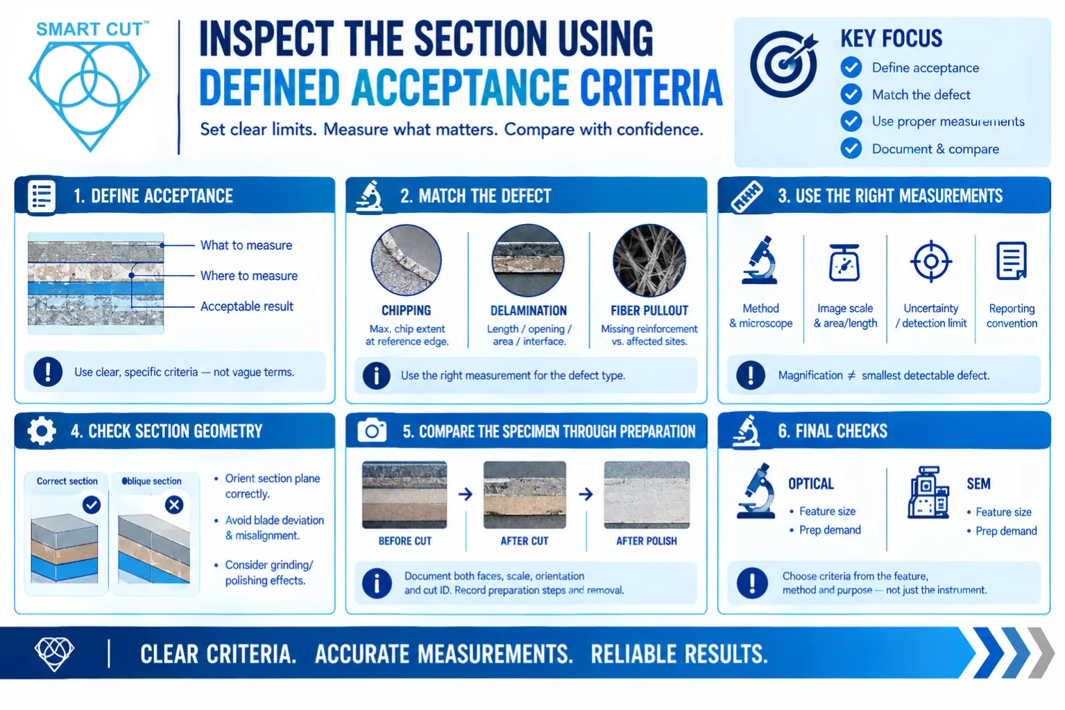
Define acceptance before cutting. Terms such as minor chipping, good finish, or no significant delamination are insufficient when different operators may interpret them differently. State what will be measured, where it will be measured, and what result is acceptable for the intended analysis.
A coating thickness study may require the coating to remain continuous across a defined measurement region. A bond-line investigation may focus on the visibility and integrity of both boundaries. A composite evaluation may require controlled fiber pullout and a surface that permits reliable identification of reinforcement and matrix.
The inspection plan should identify the microscope or measurement method, image scale, inspected length or area, and reporting convention. Include the uncertainty or detection limit where it affects the decision. Magnification alone does not define the smallest defect that can be detected reliably.
Use measurements that match the defect
For edge chipping, define the reference edge and measure the maximum relevant chip extent. For delamination, define whether the criterion concerns separation length, opening, affected interface area, or another application-specific quantity. For fiber pullout, distinguish the extent of missing reinforcement from a simple count of affected sites.
Set numerical limits from the sample requirement, inspection method, or applicable specification. There is no universal acceptable chip size or delamination length for every multilayer specimen. A defect acceptable outside the measurement region may be unacceptable within the feature being investigated.
Check section geometry as well as damage. For thickness measurements, orient the section plane appropriately relative to the layer. An oblique section can increase apparent layer thickness. Blade deviation and specimen misalignment can complicate the measurement further. Subsequent grinding and polishing may also introduce relief or edge rounding that changes the apparent boundary.
Compare the specimen through preparation
Photograph accessible features before cutting where practical. After sectioning, document both cut faces when available, including entry, central engagement, and exit regions. Preserve scale, orientation, and cut identification in the images.
Repeat the relevant inspection after grinding and polishing. Record the preparation sequence and material removal when it matters to the investigation. Damage can become less visible as material is removed, while finishing can introduce new artifacts. These observations help evaluate preparation effects but do not independently establish the origin of every defect.
A crack that disappears after additional preparation may have been confined near the cut surface. Its disappearance alone does not prove that sectioning created it. Use the specimen history, crack morphology, reference observations, and additional sections where appropriate to support the interpretation.
Optical microscopy and scanning electron microscopy can both require demanding preparation. Select the acceptance criteria from the feature size, imaging method, and measurement purpose. Do not assume that one instrument category automatically requires stricter criteria in every application.
Troubleshoot by defect location and cutting behavior
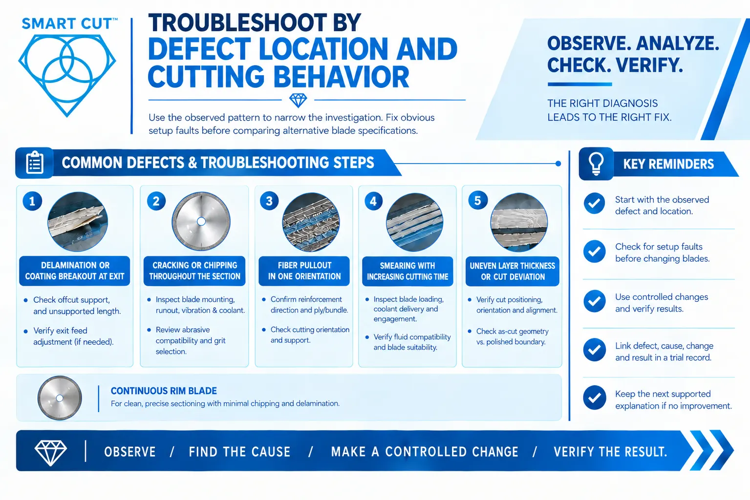
Use the observed pattern to narrow the investigation. A list of possible causes is useful only when it leads to a controlled check and a way to verify the result. Correct an obvious setup fault before comparing alternative blade specifications.
Delamination or coating breakout at exit
First inspect offcut support, the remaining unsupported length, and the direction of the cutting action at exit. Check for specimen movement as the final ligament separates. Where the machine permits controlled changes through the cut, evaluate an appropriate exit feed adjustment after confirming support. Repeat the inspection at the same exit location.
Cracking or chipping throughout the section
Inspect blade mounting, runout, fixture security, vibration, coolant access, and blade condition. Review abrasive compatibility and grit selection after mechanical problems have been addressed. Compare the next trial across the full cut rather than accepting improvement at only one location.
Fiber pullout concentrated in one orientation
Confirm the reinforcement direction and whether the defect follows particular plies or bundles. Evaluate the cutting orientation and local support with the composite architecture in mind. Where the inspection objective permits a different orientation, test it under comparable conditions. Record the orientation associated with the acceptable result.
Smearing with increasing cutting time
Inspect for blade loading, restricted coolant delivery, and changing engagement. Verify fluid compatibility and blade suitability for the ductile or polymer constituent. Condition the blade only by an approved method when appropriate. Recheck both cutting behavior and whether the affected interface becomes clearly visible after the intended preparation.
Uneven apparent layer thickness or cut deviation
Verify cut positioning, section orientation, specimen movement, and blade alignment before attributing the observation to the material. Inspect the as-cut geometry separately from the polished boundary. If the apparent variation develops during finishing, investigate polishing relief, edge rounding, and preparation alignment as well as the sectioning process.
Keep a trial record linking the observed defect, suspected cause, controlled change, and inspection result. If an adjustment does not improve the relevant measurement, retain that result and investigate the next supported explanation.
Apply the method to representative material systems
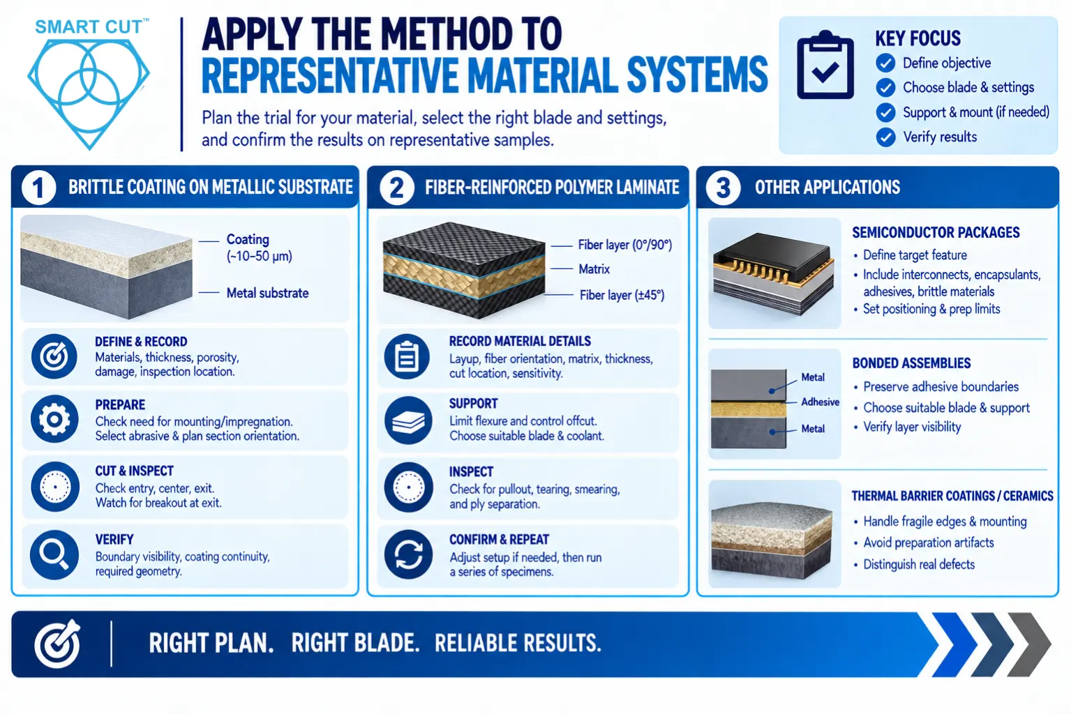
The following examples illustrate how to organize a trial. They are hypothetical preparation scenarios, not reported test results. Exact blade specifications, cutting parameters, and acceptance limits must be established for the actual specimen and equipment.
Example: brittle coating on a metallic substrate
The objective is to measure coating thickness and examine the coating-to-substrate boundary. Begin by recording coating and substrate materials, approximate thicknesses, porosity, visible damage, and the location to be inspected. Include any intermediate bond layer in the description.
Evaluate whether the coating requires mounting or impregnation before sectioning. Select the abrasive with regard to both the coating and the metallic substrate. Plan the section orientation for the intended thickness measurement and support the fragile edge without loading it directly.
On representative material, compare the as-cut coating at entry, through the central region, and at exit. If breakout is concentrated at exit, investigate support and cutting direction before replacing a blade that performs acceptably through the rest of the section. After finishing, verify boundary visibility, coating continuity, and the geometry required for measurement.
Example: fiber-reinforced polymer laminate
The objective is to examine ply boundaries and local reinforcement condition. Record the layup, fiber orientation, matrix type, thickness, cut location, and known sensitivity to heat or fluids. Mark the orientation on a suitable reference surface so that images can be related to the original laminate.
Support the specimen to limit flexure and control the final offcut. Select a blade and coolant appropriate to the reinforcement and matrix. Inspect the trial for pullout, matrix tearing, smearing, and separation between plies.
If pullout follows one reinforcement direction, investigate orientation and local support. If smearing accompanies deteriorating cutting behavior, inspect blade loading and coolant delivery. Finish representative sections and confirm that the internal architecture remains interpretable. Repeat the successful setup before adopting it for a series of specimens.
Extend the approach to other applications
For semiconductor packages, define the target feature and the allowable positioning and preparation error before cutting. Include metallic interconnects, encapsulants, adhesives, and brittle constituents in the material description. For bonded assemblies, preserve the boundaries needed to examine the adhesive layer. For thermal barrier coatings and technical ceramics, pay particular attention to fragile edges, mounting, and the distinction between preparation artifacts and original defects.
Verify repeatability and document the procedure
One acceptable trial demonstrates that the setup can produce an acceptable section under those conditions. It does not establish repeatability across different specimens, operators, or stages of blade wear. Select a confirmation plan appropriate to the material variability, specimen value, and inspection requirement.
Repeat the procedure on representative material and evaluate the same acceptance criteria. Include different locations or relevant orientations when the architecture varies. Where practical, check performance over the blade condition range expected during normal work. The number of confirmation cuts should reflect the application risk and variability. No single count demonstrates suitability for every application.
Record the material description, cut location, orientation, mounting method, fixture arrangement, machine, blade specification, blade condition, RPM, feed mode, coolant, and preparation sequence. Retain the inspection method, acceptance limits, images, results, and the person responsible for accepting the procedure.
Define reevaluation triggers. Changes in the material stack, coating thickness, adhesive, reinforcement orientation, blade construction, mounting method, fixture, or operating conditions may require confirmation before the procedure is transferred. Similar external dimensions do not establish equivalent cutting behavior.
Use the term qualified process only when the applicable qualification requirements have been met. Otherwise, describe the record as a verified sectioning procedure and state the material and operating conditions for which it has been demonstrated.
Get material-specific sectioning assistance
UKAM Industrial Superhard Tools manufactures precision diamond and CBN tools and offers precision cutting systems, workholding options, coolants, and application support. Selection should begin with your material stack and the condition required for the final section.
For a useful application review, provide the constituent materials, individual layer thicknesses, specimen dimensions, inspection objective, machine, current blade, feed mode, RPM, coolant, and photographs of the observed damage. Identify where the blade enters and exits and how the specimen is supported. Include any limits on kerf, section thickness, fluid exposure, or available sample quantity.
Request application assistance to evaluate blade selection, specimen support, and representative trial conditions for your coated, composite, or multilayer material. The recommended starting approach should then be verified against the acceptance criteria for your specific inspection.
Trusted by Tens of Thousands of Manufacturers, Laboratories,
Research Institutions Worldwide Since 1990
American Based Manufacturer
Established in 1990
Custom manufacturing
RELATED ARTICLES