








































Grinding Force vs. Wheel Condition: How Engineers Can Detect Wheel Dulling Before Part Quality Fails

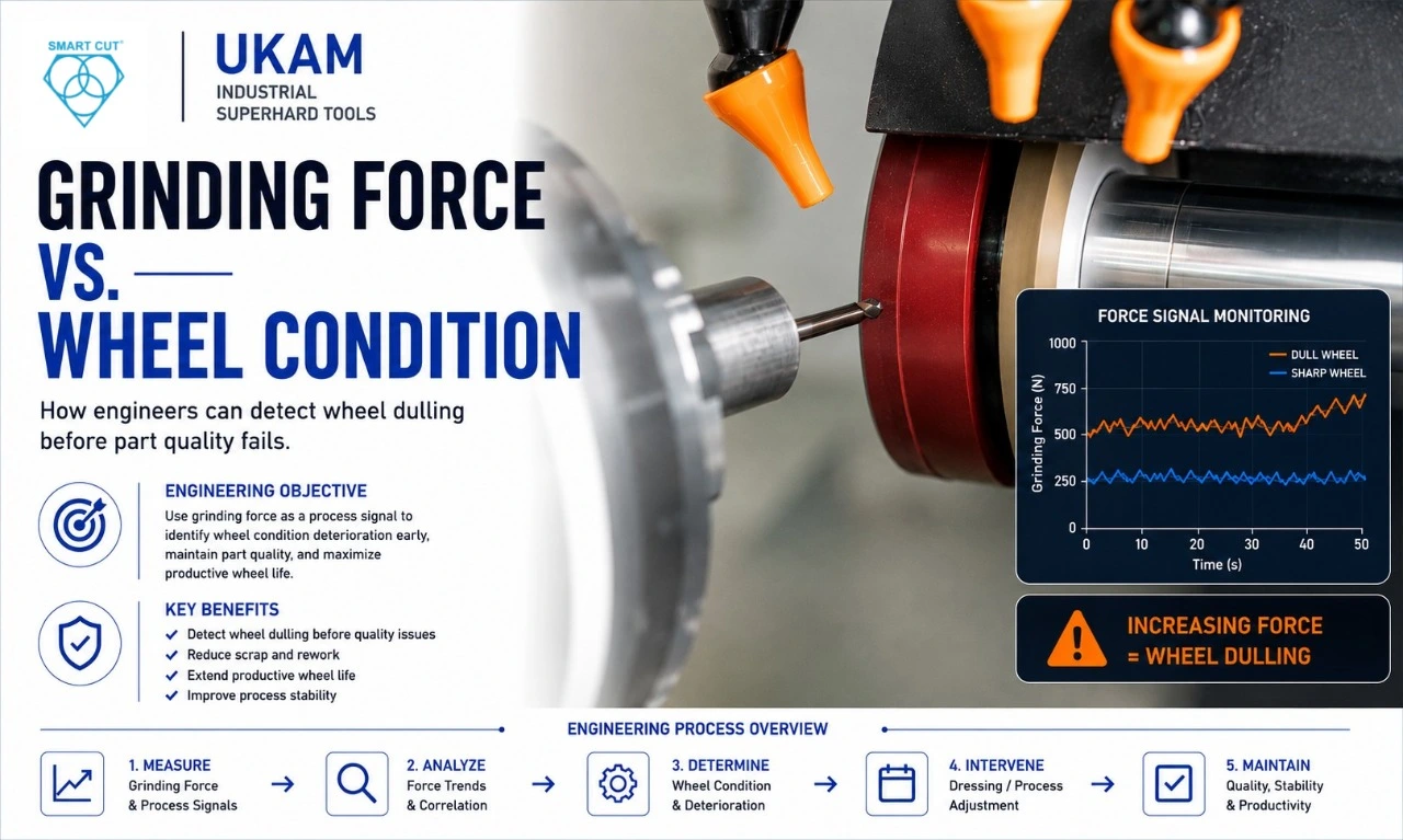
Table of Contents
Toggle
American Based Manufacturer

Established in 1990


Custom manufacturing


A grinding wheel does not necessarily reach the end of its useful production life when the abrasive is physically worn away.
In many grinding operations, the process begins to deteriorate while the wheel still appears usable. Grinding force may increase. Spindle load can rise. Surface finish may begin to change. Dressing intervals may shorten. Dimensional stability can deteriorate. Thermal damage may eventually appear.
By the time grinding burn, poor finish, or dimensional drift is detected during final inspection, the wheel may already have been operating outside its most effective process window.
Engineering Question: Can changes in grinding force identify deterioration in wheel condition before part quality fails?
In a controlled grinding process, the answer can be yes—but only when force is treated as a trend and process signal, not as a universal pass/fail number.
UKAM’s current technical guidance on diamond and CBN wheel performance already identifies increasing grinding force, spindle load, poor finish, inadequate dressing, and insufficient coolant as important troubleshooting signals. The opportunity here is to go one step further: use those signals systematically to establish a wheel-condition baseline, identify a deterioration trend, and determine when intervention is justified.
The objective is not simply to determine how much abrasive remains on a wheel. The objective is to determine: How long can the wheel continue producing acceptable parts within the required process window?
Why Grinding Force Matters in Wheel-Condition Monitoring
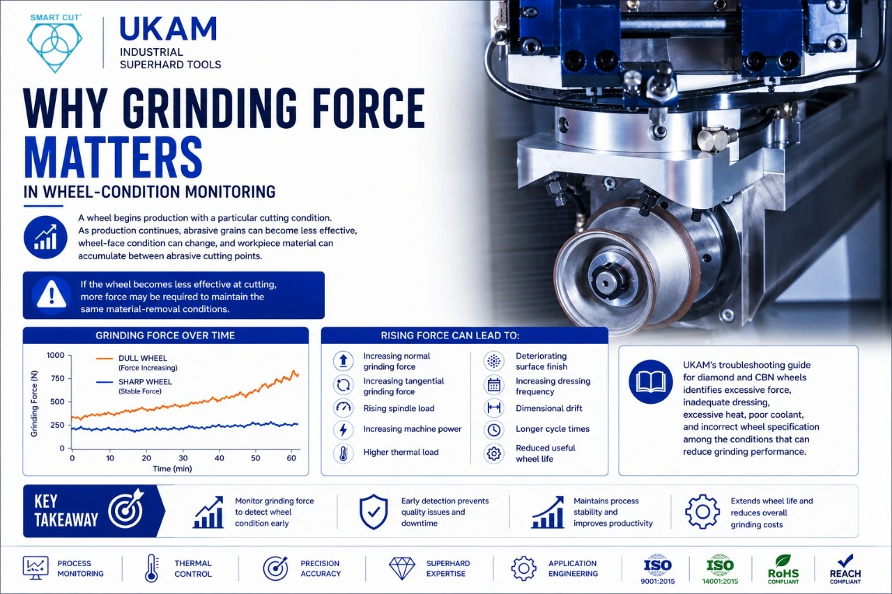
Grinding force is the resistance generated as abrasive grains interact with the workpiece. Some grinding force is expected in every grinding operation. The useful information comes from how that force changes when the process parameters remain controlled.
A wheel begins production with a particular cutting condition. As production continues, abrasive grains can become less effective, wheel-face condition can change, and workpiece material can accumulate between abrasive cutting points.
If the wheel becomes less effective at cutting, more force may be required to maintain the same material-removal conditions. That change can appear as:
- Increasing normal grinding force
- Increasing tangential grinding force
- Rising spindle load
- Increasing machine power
- Higher thermal load
- Deteriorating surface finish
- Increasing dressing frequency
- Dimensional drift
- Longer cycle times
- Reduced useful wheel life
UKAM’s troubleshooting guide for diamond and CBN wheels similarly identifies excessive force, inadequate dressing, excessive heat, poor coolant, and incorrect wheel specification among the conditions that can reduce grinding performance.
Engineering Question
If grinding force increases, does that automatically mean the wheel is dull? No. An increase may be associated with wheel dulling, but it can also result from:
- Wheel loading
- Dressing condition
- Incorrect wheel specification
- Feed changes
- Depth-of-cut changes
- Wheel-speed changes
- Workpiece variation
- Coolant delivery
- Machine condition
- Increased contact area
- Runout or mounting problems
The correct response is therefore to investigate the force trend against the complete process rather than immediately replacing the wheel.
Wheel Wear, Wheel Dulling, and Production Life Are Different
One of the most important distinctions in grinding-process control is the difference between physical wheel wear and production wheel life.
Physical wheel wear describes what is happening to the wheel. Production life describes how long the wheel can continue producing parts that meet the required specifications. Those endpoints do not necessarily occur at the same time.
A wheel may still have substantial abrasive remaining while grinding force is increasing, surface finish is deteriorating, dimensions are drifting, burn is developing, and dressing is becoming more frequent.
This distinction is also reflected in UKAM’s current CBN grinding wheel guidance, which separates physical wheel life from the point at which a wheel can no longer consistently produce acceptable parts. The same distinction applies to non-wheel formats — precision diamond blades and diamond backgrinding wheels used in wafer thinning can retain abrasive while cutting efficiency has already declined.
Wheel Condition vs. Production Condition
|
Observed Condition |
Physical Wheel Status |
Production Status |
|---|---|---|
|
Low wear, stable force, good parts |
Good |
Acceptable |
|
Moderate wear, stable quality |
Usable |
Acceptable |
|
Low visible wear, rising force |
Usable |
Investigate |
|
Good geometry, deteriorating finish |
Usable |
Process warning |
|
Good wheel size, dimensional drift |
Usable |
Process failure |
|
Burn developing during production |
Usable |
Process failure |
This is why measuring wheel diameter alone is not enough. The more useful question is: Is the wheel still producing acceptable parts at the required rate and cost?
What Causes Grinding Force to Increase?
A rising force trend can result from several different wheel and process mechanisms.
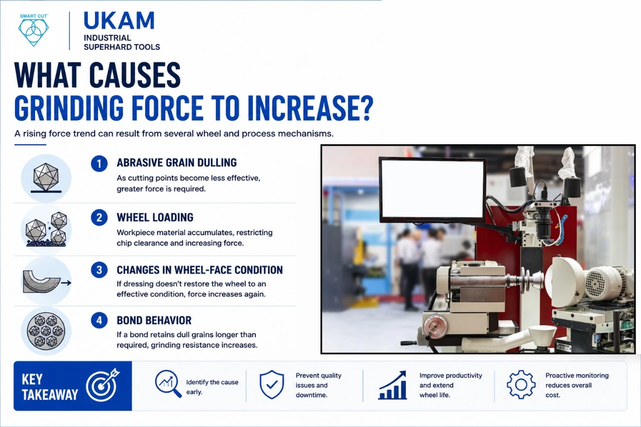
1. Abrasive Grain Dulling
Abrasive grains do not necessarily maintain the same effective cutting geometry throughout their working life. As a cutting point becomes less effective, the grinding interaction can shift toward greater rubbing and plowing. The machine may then require greater force to maintain the same grinding conditions.
A progressive force increase under otherwise controlled parameters can therefore indicate that the wheel’s cutting condition is changing.
UKAM’s current wheel-performance guidance on wheel glazing describes diamond dulling as a mechanism that can increase grinding force and heat while reducing effective cutting action.
2. Wheel Loading
Workpiece material can accumulate on or between abrasive cutting points. Loading changes the active wheel surface and can restrict chip clearance. Depending on the material, bond, coolant, grit, concentration, and operating conditions, loading can contribute to:
- Higher grinding force
- Increased heat generation
- Poor surface finish
- Reduced cutting efficiency
- Shorter useful wheel life
If force increases together with visible loading, the investigation should not stop at the wheel face. Check:
- Bond behavior
- Coolant delivery
- Chip clearance
- Dressing
- Abrasive specification
- Workpiece characteristics
UKAM’s loading and glazing guidance also distinguishes loading from glazing and emphasizes evaluating wheel specification, dressing, coolant, and machine conditions together. Loading is also a well-documented failure mode discussed in UKAM’s five tips for extending electroplated diamond wheel life, where feed rate and coolant flow are the two most common contributors.
3. Changes in Wheel-Face Condition
A grinding wheel must maintain the appropriate cutting condition throughout its production interval. Dressing or conditioning is used to restore the required wheel-face condition and geometry according to the wheel construction and application.
The important question is not simply: Was the wheel dressed? It is: Did dressing restore the wheel to an effective and repeatable cutting condition?
If force drops after dressing and then gradually increases again, the pattern provides useful evidence that wheel-face condition is influencing the process.
UKAM’s current dressing guidance for diamond dressers recommends evaluating dressing frequency, dressing depth, dressing method, wheel condition, surface finish, dimensional accuracy, and grinding forces together.
4. Bond Behavior
Bond selection affects how abrasive grains are retained and exposed. If a bond retains dull grains longer than the application requires, the cutting surface can become less effective and grinding resistance can increase.
This is why a harder bond is not automatically a better bond. The bond needs to provide the appropriate balance between abrasive retention, cutting action, form control, dressing behavior, and required wheel life.
See UKAM’s guide to choosing the correct diamond bond type for how resin, metal, vitrified, and hybrid bonds affect retention and exposure, and the broader diamond vs. CBN tool comparison for matching abrasive type to workpiece material before bond selection.
Engineering Insight:
A wheel that holds abrasive longer is not automatically a wheel that produces better parts. If excessive retention prevents effective exposure of fresh cutting points, longer physical wheel life can come at the expense of cutting efficiency.
The Force Trend Matters More Than a Single Number
A single grinding-force measurement has limited value without context. A trend across the production cycle is much more informative.
Consider this illustrative example only. The values below are not UKAM production data or universal engineering thresholds; they demonstrate how an engineer could structure a monitoring trial.
|
Parts Produced |
Grinding Force |
Surface Finish |
Process Interpretation |
|---|---|---|---|
|
1 |
100 N |
Within specification |
Baseline |
|
25 |
103 N |
Within specification |
Stable |
|
50 |
108 N |
Within specification |
Monitor |
|
75 |
116 N |
Slight change |
Investigate |
|
100 |
125 N |
Near specification limit |
Intervention approaching |
|
110 |
138 N |
Outside specification |
Process failure |
The important information is not that force eventually reached 138 N. The important information is that force was progressively increasing before the part failed. That creates an opportunity to intervene before quality becomes unacceptable.
Engineering Insight:
The objective of force monitoring is not to eliminate inspection. It is to identify process deterioration early enough that inspection does not become the first indication of failure.
How to Establish a Force Threshold Before Quality Failure
A force threshold should not be copied from another machine, wheel, or material. It should be developed from the actual production process.
Consider another illustrative example: Freshly dressed wheel: 100 N. 50 parts: 108 N. 75 parts: 116 N. 85 parts: 121 N. Surface finish approaches the specification limit at 85 parts. Dressing restores force to 101 N.
In this example, 121 N is not a universal dressing threshold. Instead, the production trial suggests that the combination of approximately 121 N plus approaching finish limit is associated with the end of the useful dressing interval for that particular process.
That distinction is critical. The threshold should be based on the relationship between force, wheel condition, part quality, and production decision, rather than force alone.
What Should Be Measured With Grinding Force?
Grinding force becomes significantly more useful when it is recorded with other production measurements. A practical wheel-condition baseline should include:
- Grinding force
- Spindle load or power
- Wheel speed
- Feed
- Depth of cut
- Workpiece speed where applicable
- Parts produced
- Dressing interval
- Dressing depth
- Wheel wear
- Surface finish
- Dimensional accuracy
- Grinding burn
- Coolant condition
- Scrap and rework
- Cycle time
UKAM’s current CBN qualification guidance similarly recommends evaluating grinding force alongside surface finish, dimensional accuracy, burn, wheel wear, dressing frequency, cycle time, and scrap. The same baseline discipline applies to fine-grinding formats such as UKAM’s SMART CUT fine grinding fixed-abrasive plates and to abrasive grinding belts used in metallography sample preparation, where the same force-and-quality correlation determines when to change abrasive.
This provides the context needed to answer a critical question: Is the change in grinding force actually affecting production?
The Most Important Measurement After Dressing
One of the most useful observations in a wheel-condition trial is what happens immediately after dressing. Ask: Does grinding force return to the original baseline after dressing?
Three different patterns can provide three different directions for investigation.
Pattern 1: Force Drops After Dressing
This suggests that wheel-face condition was contributing to the increased resistance. Continue monitoring how quickly force rises again, whether surface finish improves, whether dimensions stabilize, and whether thermal behavior improves.
Pattern 2: Force Does Not Change Significantly After Dressing
Investigate dressing effectiveness, dressing depth, dressing method, wheel specification, bond, grit, concentration, wheel speed, machine condition, and coolant delivery.
If dressing does not restore the process, the issue may not be simply a dull wheel face.
Pattern 3: Force Drops After Dressing but Rises Again Quickly
The wheel may be returning to an unfavorable cutting condition too rapidly. Investigate dressing interval, bond behavior, wheel specification, loading, coolant, process aggressiveness, and contact area.
Engineering Question
How many acceptable parts are produced before force returns to the intervention level? That number is often more useful than simply asking how long the wheel physically lasts.
Establishing a Reliable Grinding-Force Baseline
Before using grinding force as a wheel-condition indicator, engineers need to establish what normal looks like.
Step 1: Document the Workpiece
Record exact material grade, hardness, heat treatment, stock allowance, part geometry, and grinding contact area. A change in incoming material can change grinding behavior even when the wheel and machine have not changed.
Step 2: Document the Wheel
Record abrasive, grit, concentration where applicable, bond, diameter, width, bore, profile, and manufacturer specification. Without this information, force trends cannot be compared reliably between wheel specifications.
Grit specification should reference a documented diamond mesh size chart and, where relevant, the diamond concentration level used in the wheel. UKAM’s SMART CUT resin bond diamond wheels, 2A2T diamond and CBN wheels, and 11A2 diamond and CBN wheels each illustrate how specification detail is documented for a given wheel geometry.
Step 3: Check the Machine
Verify spindle speed capability, spindle condition, runout, machine rigidity, wheel mounting, flange condition, workholding, and dressing capability.
UKAM’s current technical guidance similarly recommends checking spindle condition, runout, mounting, machine stability, dressing capability, and coolant delivery during wheel qualification for edge grinding applications.
Step 4: Record Process Conditions
Document wheel speed, feed, depth of cut, workpiece speed, dressing method, dressing parameters, coolant type, coolant concentration, flow, pressure, and nozzle position. A force measurement without its corresponding process conditions can be difficult to interpret.
For guidance on documenting coolant delivery specifically, see UKAM’s overview of diamond tool coolant use.
Normal vs. Abnormal Grinding-Force Trends
A practical way to use force monitoring is to classify the trend rather than relying on one universal threshold.
|
Force Pattern |
Other Observation |
Investigation Direction |
|---|---|---|
|
Stable after dressing |
Good finish and dimensions |
Continue monitoring |
|
Gradual increase |
Finish gradually changes |
Wheel-face condition |
|
Gradual increase |
Visible loading |
Bond / coolant / dressing |
|
Sudden increase |
Process parameters unchanged |
Investigate disturbance |
|
Increase immediately after dressing |
Poor cutting condition |
Dressing / wheel specification |
|
Increase + temperature rise |
Thermal deterioration |
Coolant / process / wheel |
|
Stable force + dimensional drift |
Geometry changes |
Wheel form / machine |
|
Force changes between batches |
Material variation |
Hardness / material condition |
This approach prevents a common mistake: assuming every change in grinding force is a wheel-wear problem.
Grinding Force and Grinding Burn
Grinding burn is a serious indication of excessive thermal load, but burn should not automatically be treated as proof that the abrasive is wrong. Possible contributors include:
- Dull wheel
- Excessive dressing interval
- Poor coolant delivery
- Excessive feed
- Excessive depth of cut
- Incorrect wheel grade
- Excessive contact area
- Machine instability
UKAM’s troubleshooting guidance similarly identifies excessive heat, aggressive parameters, inadequate dressing, contaminated or inadequate coolant, and machine-related conditions among possible contributors to grinding problems. Thermal load is especially critical in heat-sensitive operations such as silicon wafer OD grinding and broader semiconductor wafer grinding and dicing processes, where excessive grinding heat can compromise material structure even when dimensions still pass inspection.
Engineering Question
Does burn appear immediately after dressing, or only after the wheel has produced a certain number of parts?
If burn appears immediately, investigate wheel specification, speed, feed, depth, coolant, and machine condition. If burn appears progressively later in the dressing interval, investigate wheel dulling, loading, dressing interval, wheel-face condition, and thermal accumulation.
The timing of the failure is itself a useful process signal.
Grinding Force and Surface Finish
Surface finish provides an important second signal.
Suppose grinding force increases from 100 N to 115 N while surface finish remains within specification, dimensions remain stable, no burn appears, and cycle time remains unchanged. The process may still be acceptable.
Now consider a different situation: force increases from 100 N to 115 N, surface roughness approaches the specification limit, dimensions begin drifting, and dressing frequency increases. The same force increase now has much greater production significance.
Engineering Insight:
A force trend becomes meaningful when it can be connected to a change in the product or process requirement. That is why wheel-condition monitoring should combine process measurements with part-quality measurements.
Grinding Force and Dimensional Drift
Dimensional drift does not always indicate wheel dulling. A wheel can remain physically intact while its geometry, cutting condition, or interaction with the machine changes.
If dimensions begin to drift, investigate wheel form, wheel wear, dressing consistency, spindle runout, machine rigidity, workholding, thermal effects, and measurement repeatability.
If grinding force rises at the same time as dimensional drift, wheel condition becomes a stronger candidate—but it should still be evaluated against the rest of the process.
Coolant Can Make a Wheel Look Like the Problem
Coolant delivery and wheel condition are closely connected. Poor coolant delivery can contribute to grinding burn, surface damage, wheel loading, poor finish, dimensional instability, and reduced wheel life.
UKAM’s technical guidance recommends evaluating coolant concentration, flow, nozzle alignment, filtration, pressure, and delivery to the actual grinding interface, as covered in selecting the right coolant method for diamond and CBN tools.
Engineering Insight:
Before replacing a wheel because force and temperature are increasing, verify that coolant — such as UKAM’s water soluble coolant — is reaching the grinding interface as intended. A process problem can appear to be a wheel problem.
What Happens When Force Changes Between Material Batches?
Incoming material variation is another frequently overlooked variable.
Suppose wheel specification is unchanged, machine settings are unchanged, dressing is unchanged, and coolant is unchanged, but grinding force increases significantly when a new material batch enters production.
The investigation should include material grade, actual hardness, heat treatment, stock allowance, and incoming material condition. The wheel should not automatically be blamed.
Engineering Question
Did the grinding process change, or did the workpiece entering the process change? That question should be answered before changing the abrasive system.
Grinding Force and Dressing Interval
Many shops use a fixed rule such as: Dress every 50 parts. A fixed interval can work when the process is stable, but it does not necessarily tell you whether the wheel is being used efficiently.
Consider this illustrative example: Process A dresses every 100 parts, with finish beginning to deteriorate after 80 parts, higher dimensional variation, and occasional scrap. Process B dresses every 70 parts, with stable finish, stable dimensions, predictable production, and lower scrap.
Process B may provide the better production result despite having a shorter dressing interval. The objective should therefore be maximum acceptable production between dressing events—not maximum parts between dressing events.
UKAM’s current dressing frequency and diamond dresser guidance similarly recommends documenting dressing frequency and evaluating it against actual wheel performance and quality rather than treating dressing as an isolated maintenance action.
Common Mistakes When Using Grinding Force to Monitor Wheel Condition
Mistake 1: Using a Universal Force Limit
A grinding-force value that is normal for one application may be unsuitable for another. Machine, wheel, material, contact area, speed, feed, and depth all influence force. Better approach: establish an application-specific baseline.
Mistake 2: Measuring Force Without Process Parameters
A force change means little if feed, speed, depth, or stock allowance changed at the same time. Better approach: record force and process parameters together.
Mistake 3: Treating Every Force Increase as Wheel Wear
Force is an indicator, not a diagnosis. Better approach: investigate wheel condition, dressing, coolant, workpiece, and machine condition.
Mistake 4: Waiting for Burn or Scrap
Burn and scrap are late indicators. Better approach: use force trends and other process signals to identify deterioration earlier.
Mistake 5: Measuring Only Wheel Diameter
Physical wheel size does not define production life, whether the tool is a bonded wheel or a diamond blade where the same principle applies to segment height. Better approach: measure acceptable production.
Mistake 6: Dressing More Frequently Without Finding the Cause
Shortening the dressing interval can temporarily restore cutting performance while hiding the underlying problem. Better approach: investigate why the wheel is losing cutting effectiveness.
Mistake 7: Running a Short Trial
A few acceptable parts do not demonstrate stable wheel performance. Progressive wheel deterioration can appear only after sufficient production. Better approach: run enough parts to expose the useful production interval.
Mistake 8: Changing Several Variables at Once
Changing wheel, speed, feed, coolant, and dressing simultaneously makes the result difficult to interpret. Better approach: establish a baseline and change major variables systematically.
Mistake 9: Measuring Only Wheel Life
A wheel that lasts longer but produces longer cycle times, poorer finish, more scrap, or more dressing may not be the better wheel. Better approach: measure the complete production result.
UKAM’s current CBN selection guidance makes the same recommendation: changing one major variable at a time makes the relationship between wheel specification and production results easier to identify. This same discipline extends to blade-based cutting operations, including wafering blade selection, diamond and CBN wafering blade specification, and diamond band saw blade selection, where isolating one variable at a time is equally essential for diagnosing performance changes.
Wheel Life vs. Production Life
This distinction should be included in every serious wheel qualification. A wheel may have physical life — abrasive remains and the wheel can physically continue operating — but production life ends when the wheel can no longer consistently produce acceptable parts within the required process window.
|
Condition |
Physical Wheel |
Production Decision |
|---|---|---|
|
Low wear, stable force |
Good |
Continue |
|
Moderate wear, stable quality |
Usable |
Continue |
|
Rising force, good parts |
Usable |
Monitor |
|
Rising force + poor finish |
Usable |
Investigate |
|
Dimensional drift |
Usable |
Process failure |
|
Burn |
Usable |
Process failure |
The wheel does not have to be physically exhausted before its useful production life ends.
Can Spindle Power Be Used to Monitor Wheel Condition?
Direct grinding-force measurement is one possible approach. Machine power or spindle-load information can also provide useful information about changing grinding resistance where direct force measurement is not practical.
The appropriate signal depends on machine architecture, available instrumentation, required measurement accuracy, production volume, and process sensitivity.
|
Signal |
Potential Information |
|---|---|
|
Grinding force |
Cutting resistance |
|
Spindle power/load |
Machine resistance |
|
Acoustic emission |
Wheel/workpiece interaction |
|
Vibration |
Process and machine instability |
|
Surface finish |
Resulting part quality |
|
Wheel inspection |
Physical wheel condition |
|
Combined measurements |
Broader process condition |
Not every production environment requires sophisticated online monitoring. For many applications, beginning with force, dressing interval, surface finish, dimensions, and parts produced can establish a useful wheel-condition baseline.
From Wheel Monitoring to Predictive Process Control
Once a reliable force trend has been established, the same concept can support more advanced process monitoring. Possible signals include grinding force, spindle power, acoustic emission, vibration, temperature, surface condition, and wheel profile.
The objective is not to introduce technology for its own sake. The objective is to identify process deterioration before it becomes product failure. A simple production spreadsheet can provide useful information before a fully automated monitoring system is justified.
Engineering Insight:
Start with the simplest signal that reliably predicts a production problem. If grinding force, surface finish, and dressing interval already provide a useful warning, additional instrumentation should have a clear purpose.
A Practical Wheel-Condition Dashboard
A production team can begin with a simple monitoring table. The values below are illustrative, not UKAM production limits.
|
Measurement |
Freshly Dressed |
Mid-Run |
Near Dressing Limit |
Decision |
|---|---|---|---|---|
|
Grinding force |
100 N |
110 N |
120 N |
Investigate trend |
|
Spindle load |
42% |
46% |
51% |
Investigate trend |
|
Surface finish |
Within spec. |
Stable |
Near limit |
Monitor |
|
Dimension |
Stable |
Stable |
Drifting |
Investigate |
|
Wheel wear |
Recorded |
Recorded |
Recorded |
Evaluate |
|
Parts since dress |
0 |
50 |
80 |
Compare |
|
Coolant |
Verified |
Verified |
Verified |
Continue |
|
Burn |
None |
None |
None |
Continue |
The thresholds should be established from the actual application. They should not be copied from another grinding operation simply because the machine or wheel appears similar.
A Six-Stage Wheel-Condition Qualification Process
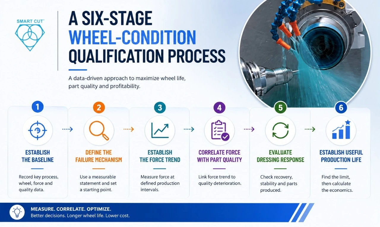
Phase 1: Establish the Baseline
Record workpiece material, hardness, current wheel, wheel dimensions, wheel speed, feed, depth, coolant, dressing, cycle time, grinding force, surface finish, dimensional accuracy, and scrap. The baseline should represent a known acceptable production condition.
Phase 2: Define the Failure Mechanism
Avoid “the wheel does not last.” Use a measurable statement: “Grinding force increases progressively after 60 parts and surface finish approaches the specification limit after 80 parts.” The second statement gives the investigation a measurable starting point.
Phase 3: Establish the Force Trend
Measure force at defined production intervals. The interval should be appropriate to cycle time, production volume, expected wheel life, and quality requirement.
Phase 4: Correlate Force With Part Quality
At the same intervals, measure surface finish, dimensions, profile, burn, and scrap. The goal is to identify the force trend associated with actual production deterioration.
Phase 5: Evaluate Dressing Response
Record force before dressing, force immediately after dressing, and force during subsequent production. Then determine how much force was restored, how quickly force increased again, whether surface finish recovered, whether dimensions stabilized, and how many acceptable parts were produced before deterioration returned.
Phase 6: Establish Useful Production Life
Determine the point at which the wheel can no longer consistently produce acceptable parts. Then calculate the economics, including wheel cost, wheel consumption, dressing, dressing downtime, machine time, cycle time, labor, coolant, scrap, rework, and acceptable parts.
UKAM’s current CBN qualification guidance uses the same broader principle: wheel comparisons should include cycle time, wheel life, dressing, scrap, and cost per acceptable part, rather than purchase price alone — a methodology developed through UKAM’s own research and development program.
What Should an Engineer Do When Force Starts Rising?
Use the following decision sequence.
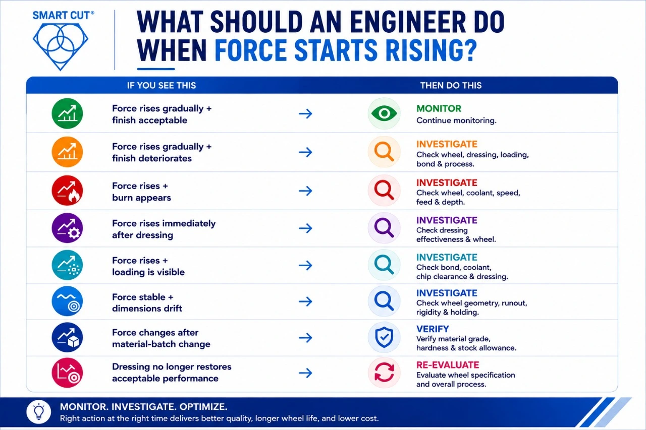
Force rises gradually + finish remains acceptable
Action: Continue monitoring. The wheel may still be within its useful production window.
Force rises gradually + finish deteriorates
Action: Investigate wheel-face condition, dressing interval, loading, bond, and process parameters.
Force rises + burn appears
Action: Investigate wheel condition, coolant, speed, feed, depth, and contact area.
Force rises immediately after dressing
Action: Investigate dressing effectiveness and wheel specification.
Force rises + loading is visible
Action: Investigate bond, coolant, chip clearance, dressing, and material characteristics.
Force remains stable + dimensions drift
Action: Investigate wheel geometry, dressing consistency, machine runout, rigidity, and workholding.
Force changes after a material-batch change
Action: Verify material grade, hardness, heat treatment, and stock allowance.
Dressing no longer restores acceptable performance
Action: Evaluate the complete wheel specification and process rather than simply shortening the dressing interval.
Frequently Asked Questions
No. Increasing force can be associated with wheel dulling or loading, but it can also result from process changes, workpiece variation, coolant problems, or machine condition.
There is no universal indicator. In a controlled process, a progressive increase in grinding force or spindle load can provide an early warning when it is correlated with surface finish, dimensions, and other production measurements.
It can help establish an application-specific dressing threshold. The threshold should be correlated with acceptable part quality rather than based on force alone.
Not necessarily. A gradual increase may be normal. The important question is whether the trend is associated with declining cutting performance or part quality.
At minimum: surface finish, dimensional accuracy, wheel wear, dressing frequency, cycle time, scrap, process parameters, and coolant condition.
In some applications, yes. Spindle load or machine power can provide useful information about changing process resistance. Its usefulness depends on the machine and application.
No. A longer dressing interval is useful only if the wheel continues producing acceptable parts throughout that interval.
They can contribute to changes in wheel loading, thermal conditions, finish, and wheel performance. Coolant delivery should therefore be verified before replacing a wheel.
Compare the force trend with material grade, hardness, heat treatment, and stock allowance. If force changes with the incoming material while the grinding process remains constant, workpiece variation should be investigated.
Wheel wear describes physical changes to the wheel. Dulling describes a reduction in effective cutting behavior. A wheel can physically retain abrasive while its cutting performance has already deteriorated.
There is no universal number of parts. The trial should run long enough to expose progressive wheel deterioration and establish the relationship between force, dressing, wheel condition, and part quality.
Not by parts alone. The useful measurement is the number of acceptable parts produced within the required process window, together with cycle time, dressing, scrap, quality, and production cost.
Engineering Checklist: Is the Wheel Still in Its Useful Production Life?
Before declaring a wheel worn out, ask:
Workpiece
- Is the material grade confirmed?
- Is hardness consistent?
- Has heat treatment been verified?
- Has stock allowance changed?
Wheel
- Is the abrasive appropriate?
- Is grit specification correct?
- Is concentration appropriate?
- Is the bond appropriate?
- Is the wheel geometry correct?
Machine
- Is spindle condition acceptable?
- Is runout controlled?
- Is mounting correct?
- Is workholding stable?
- Is machine rigidity sufficient?
Process
- Is wheel speed controlled?
- Is feed stable?
- Is depth of cut stable?
- Is contact area appropriate?
Dressing
- Is the dressing method appropriate?
- Is dressing depth consistent?
- Is the interval appropriate?
- Does dressing restore the force baseline?
Coolant
- Is concentration controlled?
- Is flow sufficient?
- Is pressure adequate?
- Is nozzle alignment correct?
- Is filtration effective?
- Does coolant reach the grinding interface?
Production
- Is grinding force stable?
- Is surface finish within specification?
- Are dimensions stable?
- Is burn absent?
- Is cycle time acceptable?
- Is scrap controlled?
- Is cost per acceptable part acceptable?
If these measurements are available, the decision to dress, adjust, or replace the wheel can be based on production evidence rather than visual judgment alone.
Final Engineering Principles
Grinding force is most useful when it is treated as one part of a complete wheel-condition monitoring system. The key principles are:
- Establish a baseline after dressing.
- Monitor the trend, not a single force value.
- Correlate force with surface finish and dimensional accuracy.
- Record dressing intervals and dressing parameters.
- Check coolant delivery before blaming the wheel.
- Verify workpiece material and hardness.
- Do not treat every force increase as proof of wheel wear.
- Use force as a diagnostic signal, not a standalone pass/fail measurement.
- Distinguish physical wheel life from production life.
- Establish dressing intervals using actual production data.
- Run trials long enough to expose progressive deterioration.
- Avoid changing several variables simultaneously.
- Measure acceptable parts, not simply total parts.
- Include cycle time, dressing, scrap, and machine time in economic evaluations.
- Treat a changing force trend as an opportunity to investigate before quality failure occurs.
The central principle is: A grinding wheel does not reach the end of its useful production life simply because abrasive has been consumed. It reaches that point when it can no longer maintain the required part quality and process performance within an acceptable production window.
Grinding-force monitoring can help engineers identify that transition earlier. Instead of waiting for grinding burn, dimensional drift, poor finish, or scrap to reveal a changing wheel condition, the process can be monitored while the change is developing.
Request a Grinding Wheel Evaluation
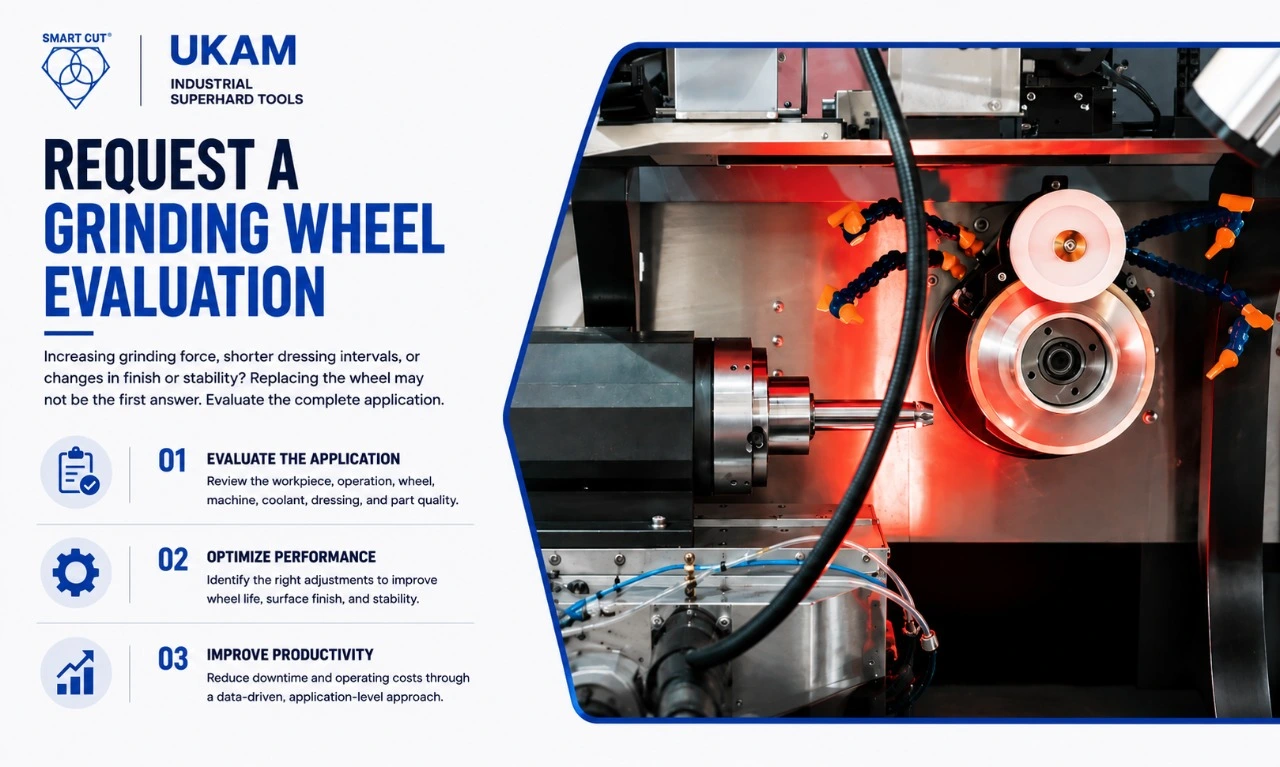
If grinding force is increasing, dressing intervals are shortening, or surface finish and dimensional stability are changing, replacing the wheel may not be the first or only solution.
The complete application should be evaluated: workpiece, hardness, operation, current wheel, grit, concentration, bond, geometry, machine, speed, feed, depth, coolant, dressing, grinding force, part quality, and production economics.
UKAM’s current technical guidance on how to select a diamond or CBN grinding wheel takes this same application-level approach, evaluating wheel specification, dressing, machine condition, coolant, grinding forces, surface quality, and production economics together. This same evaluation process is used across UKAM’s broader material range, including diamond blades for cutting glass and general guidance on cutting glass with diamond blades.
For an application-specific grinding-wheel evaluation, provide:
- Exact workpiece material and grade
- Hardness
- Grinding operation
- Current wheel specification
- Wheel dimensions
- Wheel speed
- Feed
- Depth of cut
- Dressing method
- Dressing frequency
- Coolant type and delivery
- Grinding force or spindle-load information, if available
- Cycle time
- Surface finish
- Dimensional tolerance
- Wheel life
- Scrap/rework rate
- Production volume
- Current failure mechanism
The objective is not simply to find a wheel that lasts longer. It is to determine whether the complete wheel and process combination can maintain stable cutting behavior, acceptable part quality, predictable dressing intervals, productive cycle times, and acceptable cost per acceptable part throughout production. Learn more about UKAM Industrial Superhard Tools and its engineering support team, including its diamond backgrinding wheels product line used in wafer-thinning qualification work.
Trusted by Tens of Thousands of Manufacturers, Laboratories,
Research Institutions Worldwide Since 1990
American Based Manufacturer
Established in 1990
