








































Precision Diamond Core Drilling for Photonics: How to Reduce Chipping, Improve Hole Quality, and Extend Tool Life

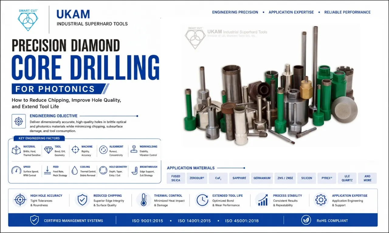
Table of Contents
Toggle
American Based Manufacturer

Established in 1990


Custom manufacturing


A hole can meet its nominal diameter and still fail a photonics application.
The entrance may be chipped. The exit edge may have broken away. The hole may have taper, poor wall quality, or subsurface damage. Tool life may be too short to support production. Or the drilling process may work on one material and become unstable on another.
For manufacturers working with brittle optical and photonics materials, hole quality is not simply a dimensional measurement.
It is the combined result of:
Material + Diamond Tool + Machine + Alignment + Workholding + Speed + Feed + Cooling + Hole Geometry + Breakthrough Strategy
This is why precision diamond core drilling should be treated as an application-engineering problem rather than simply a tool-selection exercise.
UKAM’s current photonics tooling range includes diamond core drills and drilling tools for photonics applications for materials such as fused silica, Zerodur, CaF₂, Tempax, Borofloat, germanium, ZnSe, ZnS, ULE quartz, silicon, Pyrex, and other optical materials. The company offers thin-wall, heavy-wall, miniature, micro, electroplated, sintered/metal-bond, and custom diamond drilling solutions.
The more useful engineering question is therefore:
How can engineers produce precision holes in brittle photonics materials while controlling chipping, dimensional variation, thermal load, and tool consumption?
Why Precision Drilling in Photonics Is Different
Many photonics materials combine properties that make conventional drilling challenging.
They can be:
- Hard
- Brittle
- Abrasive
- Sensitive to localized loading
- Sensitive to thermal gradients
- Difficult to machine without edge damage
- Used in applications where hole quality affects downstream performance
A ductile metal can accommodate some mechanical loading through plastic deformation. A brittle optical material has a different failure mechanism. If local stresses become excessive, cracks can initiate and propagate.
That means a drilling condition that appears only slightly more aggressive can produce a disproportionate increase in edge damage.
ENGINEERING QUESTION
What happens when the drill is capable of removing the material, but the process is applying more mechanical or thermal stress than the workpiece can tolerate?
The result may be:
- Entry chipping
- Exit breakout
- Microcracking
- Poor hole-wall condition
- Dimensional instability
- Increased scrap
So the objective is not maximum material removal. The objective is controlled material removal within the quality limits of the application.
Hole Diameter Is Only the Beginning

One of the most common mistakes in diamond-drilling applications is specifying the tool only by hole diameter.
For example: “We need a 5 mm hole.”
That information is not enough. An engineer also needs to know:
- Material
- Material thickness
- Hole depth
- Through-hole or blind-hole requirement
- Diameter tolerance
- Roundness requirement
- Taper requirement
- Entry-edge requirement
- Exit-edge requirement
- Surface-finish requirement
- Production quantity
- Machine capability
- Coolant method
- Expected tool life
Two applications requiring the same nominal hole diameter can require very different drilling solutions.
ENGINEERING INSIGHT
The required hole defines the application. The diameter only defines one part of the tool specification.
UKAM’s photonics drilling range includes different outside and inside diameters, wall thicknesses, bond types, diamond mesh sizes, mountings, depths, and tolerances, reflecting the need to match the tool to the application rather than selecting by diameter alone. For a broader look at how bond type, material, and geometry interact, see this complete expert guide to diamond core drills.
What Makes a Hole “Good”?
A production hole should be evaluated using the characteristics that actually matter to the application.
|
Hole Characteristic |
Engineering Concern |
|---|---|
|
Diameter |
Dimensional accuracy |
|
Roundness |
Geometric accuracy |
|
Taper |
Consistency through depth |
|
Entry edge |
Chipping / breakout |
|
Exit edge |
Breakthrough damage |
|
Wall quality |
Surface condition |
|
Depth |
Required geometry |
|
Position |
Location accuracy |
|
Subsurface condition |
Cracks / damage |
|
Repeatability |
Part-to-part consistency |
A drill can produce an acceptable diameter while failing another requirement.
For example:
hole diameter = acceptable,
exit chipping = unacceptable.
The drilling process has still failed.
This is why hole qualification should not rely on a single measurement.
The Three Questions Engineers Should Ask Before Selecting a Drill
Before choosing a diamond core drill, establish three things.
1. What material are you drilling?
Identify the exact material and relevant condition.
2. What hole must be produced?
Define diameter, depth, tolerance, edge quality, and surface requirements.
3. What machine will produce it?
Understand spindle capability, runout, workholding, coolant, alignment, and available process control.
Only after these questions are answered should tool construction and drilling parameters be finalized. UKAM’s about us page outlines the engineering background behind how these evaluations are typically structured for new applications.
Why Diamond Core Drilling Can Be Effective for Brittle Materials
Diamond is an abrasive cutting medium suited to many hard and brittle materials. A core drill removes material around a cylindrical path rather than removing the entire volume of material inside the hole. That can make core drilling attractive for certain larger-hole and deep-hole applications.
But core drilling is not automatically the best solution for every hole. The selection depends on hole diameter, hole depth, material, required quality, tool stability, machine capability, and production volume.
UKAM offers both hollow-core and solid diamond drilling solutions, including miniature hollow-core tools for small-diameter and deeper drilling applications.
ENGINEERING QUESTION
Is the application best served by removing the entire hole volume or by coring the material? The answer should come from the complete process requirement.
Thin-Wall vs. Heavy-Wall Core Drills
Core-drill wall thickness can affect the behavior of the tool.
UKAM’s current photonics range includes both thin-wall and heavy-wall diamond core drills, including electroplated (nickel bond) and sintered/metal-bond wafering and drilling constructions.
The appropriate wall construction depends on factors such as hole diameter, material, hole depth, required rigidity, machine conditions, desired cutting behavior, tool life, and edge-quality requirements.
ENGINEERING INSIGHT
Wall thickness is not simply a dimensional specification. It can influence the drilling process itself.
Electroplated vs. Sintered / Metal-Bond Construction
iamond drills can be constructed differently depending on the intended application. A simplified comparison:
|
Consideration |
Electroplated Construction |
Sintered / Metal-Bond Construction |
|---|---|---|
|
Diamond arrangement |
Bonded at working surface |
Distributed through bond structure |
|
Cutting behavior |
Application-specific exposed abrasive layer |
Continued abrasive exposure as bond wears |
|
Tool-life strategy |
Depends on construction and application |
Can support multi-layer abrasive exposure |
|
Typical selection factors |
Material, geometry, cutting requirements |
Material, tool life, production requirements |
This is a selection framework, not a universal performance ranking. The correct construction depends on the actual application.
UKAM’s current photonics product information describes both electroplated and sintered/metal-bond diamond drilling options, built to different bond and wall specifications depending on the application.
Chipping: The Most Visible Failure Is Not Always the Root Cause
Chipping is often where engineers first notice a problem. But the visible chip may be the final result of several interacting variables.
Potential contributors include:
- Excessive feed
- Excessive mechanical loading
- Vibration
- Tool runout
- Poor workholding
- Tool misalignment
- Inadequate coolant
- Poor breakthrough control
- Material variation
- Incorrect tool construction
This is why “the drill is chipping the material” is not yet a root-cause diagnosis. The better question is: “Under what condition does the chipping begin?”
Entry Chipping vs. Exit Chipping
The location of the damage can provide a valuable diagnostic clue.
Entry Chipping
If damage occurs when the drill first engages the workpiece, investigate alignment, initial engagement, workpiece support, runout, initial feed, and mechanical shock.
Exit Chipping
If damage occurs near breakthrough, investigate remaining material thickness, workpiece support, breakthrough condition, feed strategy, vibration, and tool stability.
Chipping Throughout the Hole
If damage occurs throughout the drilling depth, investigate tool specification, material compatibility, machine stability, coolant, tool condition, and process parameters.
ENGINEERING INSIGHT
Where the damage occurs can be as informative as how much damage occurs. UKAM’s micro drilling guide covers feed and coolant technique in more depth for smaller-diameter applications where these effects are magnified.
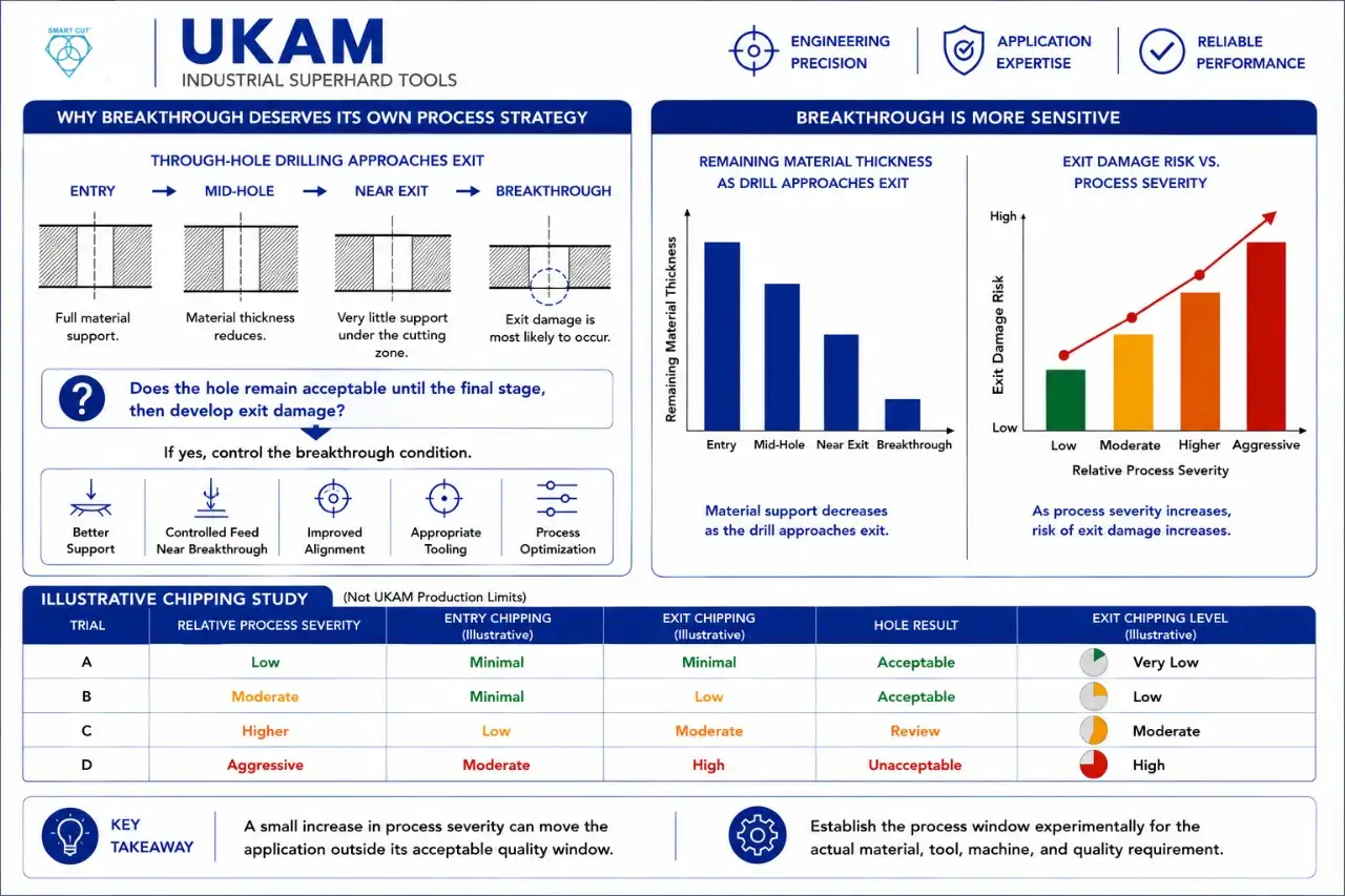
Why Breakthrough Deserves Its Own Process Strategy
A through-hole is not one continuous drilling condition. As the drill approaches the exit surface, the remaining material becomes thinner. The mechanical support available beneath the cutting zone changes.
This can make the final stage of drilling particularly sensitive to feed, vibration, workpiece support, tool alignment, and material brittleness.
ENGINEERING QUESTION
Does the hole remain acceptable until the final stage, then develop exit damage? If yes, the entire drilling process may not need to be changed — the breakthrough condition may need to be controlled.
Possible approaches can include better support, controlled feed near breakthrough, improved alignment, appropriate tooling, and process optimization. The appropriate method depends on the material and application.
Illustrative Chipping Study
The following numbers are illustrative only and are not UKAM production limits.
|
Trial |
Relative Process Severity |
Entry Chipping |
Exit Chipping |
Hole Result |
|---|---|---|---|---|
|
A |
Low |
Minimal |
Minimal |
Acceptable |
|
B |
Moderate |
Minimal |
Low |
Acceptable |
|
C |
Higher |
Low |
Moderate |
Review |
|
D |
Aggressive |
Moderate |
High |
Unacceptable |
The important observation is not that one particular feed or speed is universally correct. The important observation is that a small increase in process severity can move the application outside its acceptable quality window.
Therefore, engineers should establish the process window experimentally for the actual material, tool, machine, and quality requirement.
Hole Quality vs. Drilling Speed
Production teams naturally want shorter cycle times. But faster drilling can become counterproductive when it increases chipping, rework, scrap, tool changes, secondary finishing, and inspection requirements.
Consider this illustrative example:
|
Metric |
Process A |
Process B |
|---|---|---|
|
Drilling time |
40 sec |
28 sec |
|
Acceptable holes |
99% |
91% |
|
Rework |
1% |
7% |
|
Tool changes |
1 |
2 |
|
Secondary finishing |
Low |
High |
Process B is faster per hole. But Process A may produce more acceptable holes per production hour.
ENGINEERING INSIGHT
The fastest drilling cycle is not necessarily the most productive drilling process. A better production metric is cost and time per acceptable hole.
Heat Generation and Thermal Control
Diamond drilling involves mechanical interaction and friction at the drilling interface. That creates heat. Thermal management becomes particularly important when drilling brittle optical materials or when hole depth and production rate increase.
Coolant can help control temperature, debris, cutting-zone conditions, and tool condition.
UKAM offers water swivel adapters designed to supply water, coolant, or air through the center of compatible diamond drills to cool the drill and material in the drilling zone. Models such as the Model 5818 precision water swivel adapter and its compact variant are built for thinner-wall core drills used in optics and advanced ceramics.
ENGINEERING QUESTION
Are you measuring coolant delivery, or simply assuming the coolant is reaching the cutting interface? These are not the same thing.
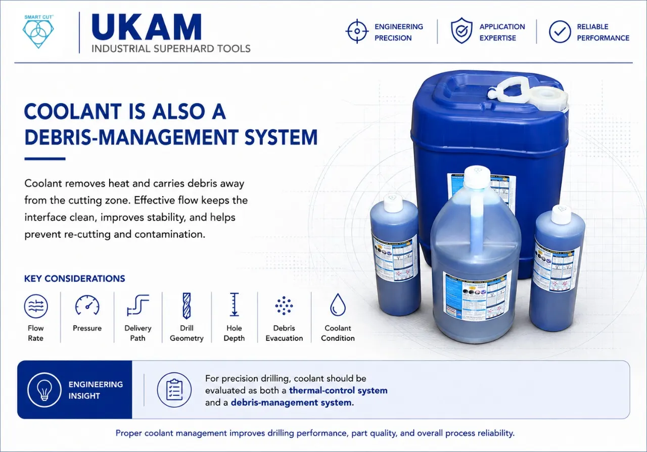
Coolant Is Also a Debris-Management System
Coolant does more than remove heat. Drilling creates particles that need to leave the cutting zone. If debris remains around the interface, it can affect drilling stability and potentially contribute to re-cutting or process contamination.
Engineers should therefore consider flow, pressure, delivery path, drill geometry, hole depth, debris evacuation, and coolant condition.
ENGINEERING INSIGHT
For precision drilling, coolant should be evaluated as both a thermal-control system and a debris-management system. A more complete breakdown of coolant selection appears in why, how, when and where to use diamond tool coolants and in UKAM’s dedicated page on coolants for diamond tools.
Why Runout Becomes Critical in Small-Hole Drilling
As the drill becomes smaller, alignment errors can become more consequential relative to the tool diameter.
Runout can contribute to oversized holes, non-round holes, uneven tool wear, vibration, chipping, and poor positional accuracy.
UKAM’s photonics range includes miniature hollow-core drills in approximately 1–3.5 mm outside diameters and micro-drilling tools for precision applications.
ENGINEERING QUESTION
If a small hole is consistently oversized, is the drill actually oversized — or is the rotating system producing additional motion? Before changing the drill diameter, check spindle runout, collet condition, tool mounting, fixture stability, tool alignment, and machine condition.
Hole Depth Changes the Process
A shallow hole and a deep hole are not simply the same application at different dimensions.
As depth increases, engineers may encounter greater tool deflection, more difficult debris evacuation, reduced coolant effectiveness, greater sensitivity to alignment, increased opportunity for taper, greater thermal accumulation, and increased stability requirements.
This is one reason tool geometry and construction should be considered together with hole depth. UKAM’s broader drilling accessories range, including depth stops and adapters, is built to support deeper and more demanding hole geometries.
Material Selection Matters
Photonics encompasses many different materials. UKAM’s current product information identifies drilling applications involving materials including fused silica, Zerodur, CaF₂, Tempax, Borofloat, germanium, ZnSe, ZnS, ULE quartz, silicon, Pyrex, and other optical materials.
Adjacent industries such as semiconductor manufacturing, lapidary and gemstone work, and glass & quartz processing share many of the same material-behavior challenges.
These materials should not automatically be treated as interchangeable. They can differ in hardness, brittleness, fracture behavior, thermal response, abrasiveness, and sensitivity to mechanical loading.
ENGINEERING INSIGHT
A drilling condition that works for one photonics material should be qualified before being transferred to another.
Why the Same Drill Can Behave Differently on Two Materials
Imagine the same diamond drill is used on two materials.
Material A
Clean entry, clean exit, stable drilling, long tool life.
Material B
Increased exit chipping, higher force, shorter tool life.
It would be tempting to conclude that the drill is defective. But the material may have a different fracture response or thermal behavior.
The correct investigation should compare Material + Tool + Process + Quality Result — rather than assuming the tool is the only variable.
A Structured Diamond Core Drill Qualification
A disciplined qualification process can prevent unnecessary trial-and-error.
Step 1: Define the Application
Material, thickness, hole diameter, hole depth, through or blind hole, diameter tolerance, surface finish, entry-edge requirement, exit-edge requirement, production quantity.
Step 2: Define the Machine
Machine type, spindle capability, runout, tool interface, workholding, coolant capability, alignment, machine rigidity.
Step 3: Define the Tool
Core-drill type, outside diameter, inside diameter, wall thickness, diamond grit, bond/construction, mounting, required tolerance.
Step 4: Establish a Baseline
Drilling time, hole diameter, roundness, taper, entry chipping, exit chipping, wall condition, tool condition, rework, scrap.
Step 5: Change One Major Variable
Possible variables include speed, feed, coolant, tool construction, grit, workholding, breakthrough strategy. Changing everything at once makes the trial difficult to interpret.
Illustrative Qualification Data
The following values are illustrative only.
|
Metric |
Trial A |
Trial B |
Trial C |
|---|---|---|---|
|
Drilling time |
45 sec |
35 sec |
27 sec |
|
Entry-edge damage |
0.06 mm |
0.07 mm |
0.13 mm |
|
Exit-edge damage |
0.09 mm |
0.11 mm |
0.28 mm |
|
Hole variation |
Low |
Low |
Moderate |
|
Acceptable holes |
97% |
98% |
89% |
|
Tool condition |
Good |
Good |
Increased wear |
Trial C is substantially faster. But it produces poorer edge quality and lower yield. Trial B may therefore be the better production condition even though it is not the fastest.
This illustrates an important principle: process optimization should maximize acceptable production, not simply minimize drilling time.
A Practical Chipping Diagnostic
When a hole begins to chip, work through the following questions.
Does damage occur at entry?
Check alignment, initial feed, runout, workpiece support, tool mounting.
Does damage occur at exit?
Check breakthrough, support, feed strategy, vibration, remaining material thickness.
Does damage occur throughout the hole?
Check tool construction, material compatibility, coolant, machine stability, tool condition.
Does damage increase with production time?
Check tool wear, debris, heat, diamond exposure, process drift.
This approach helps identify where the process is failing before changing the tooling. UKAM's technical team, including specialists such as Carlos Sanchez, regularly works through this type of diagnostic with customers before recommending a tooling change.
Tool Life Should Mean “Acceptable Hole Life”
A drill can continue physically cutting while the holes it produces become unacceptable. Therefore, tool life should be measured against production quality.
Track number of holes, hole diameter, diameter drift, chipping, surface condition, drilling time, tool wear, rework, and scrap.
ENGINEERING INSIGHT
The useful life of a diamond drill ends when it stops producing acceptable holes — not necessarily when it stops cutting.
Illustrative Tool-Life Comparison
Again, these values are illustrative only.
|
Metric |
Drill A |
Drill B |
|---|---|---|
|
Holes produced |
1,000 |
1,250 |
|
Acceptable holes |
990 |
1,150 |
|
Average drilling time |
36 sec |
29 sec |
|
Rework |
10 |
100 |
|
Tool changes |
1 |
2 |
|
Secondary finishing |
Low |
High |
Drill B produces more total holes. But Drill A produces a higher percentage of acceptable holes. If rework and secondary finishing are expensive, Drill A may have the better total production economics.
The Cost of a “Cheap” Drill
Purchase price is only one part of tooling cost. A more meaningful calculation is:
Tool cost + machine time + tool changes + rework + scrap + secondary finishing
For example, an inexpensive drill that creates additional rework can cost more than a higher-priced tool that produces stable holes.
ENGINEERING QUESTION
What is the cost of one acceptable hole — not simply the purchase price of the drill? That is the metric production engineers should ultimately compare.
Multi-layer constructions such as the SMART CUT 2020 series are one example of tooling engineered specifically to extend acceptable-hole life rather than just cutting time.
When Should a Custom Diamond Core Drill Be Considered?
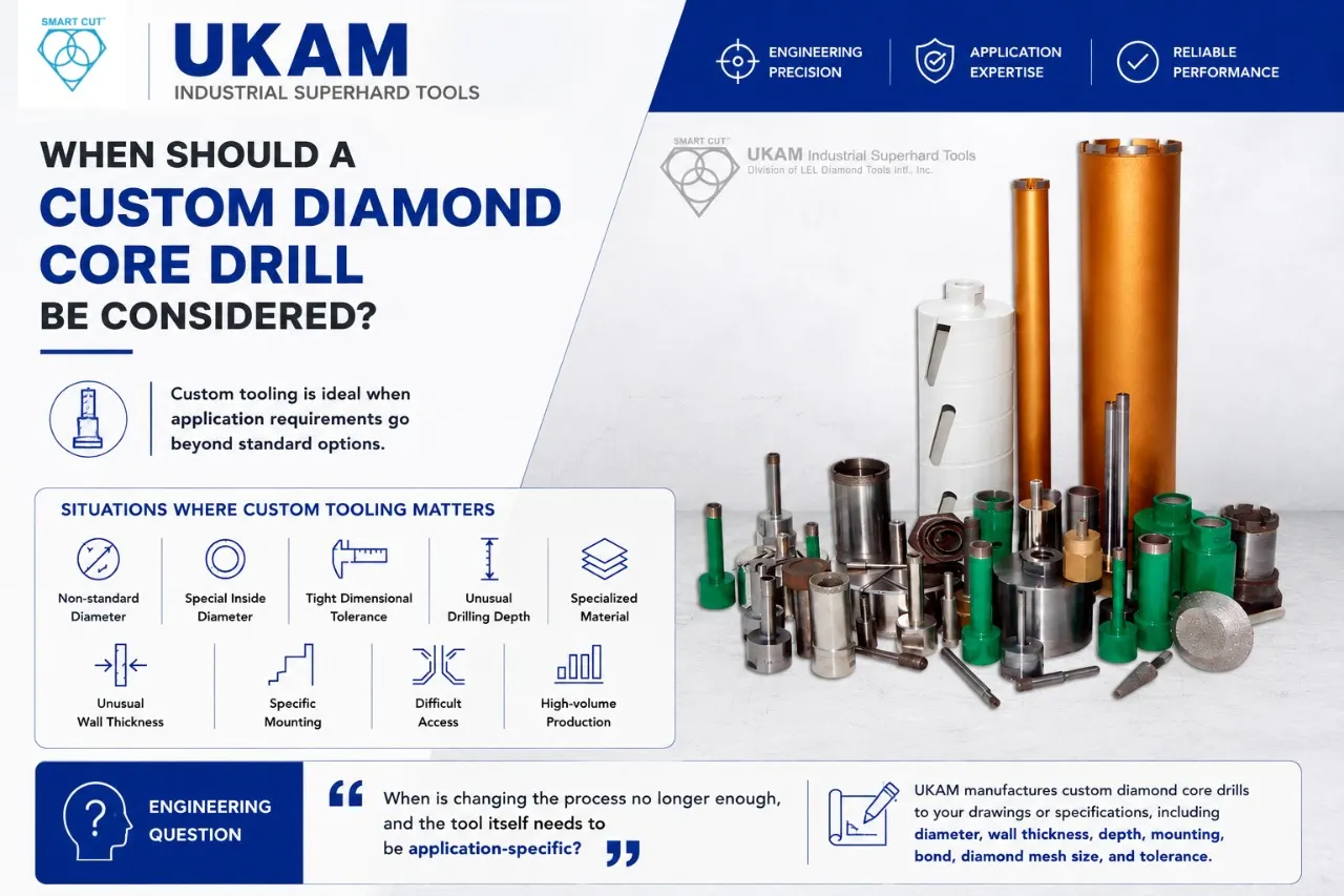
Standard tooling may be appropriate for many applications. Custom tooling becomes more relevant when requirements include non-standard diameter, special inside diameter, unusual wall thickness, specific mounting, tight dimensional tolerance, unusual drilling depth, specialized material, difficult access, or high-volume production requirements.
UKAM states that custom diamond drills can be manufactured according to drawings or application specifications, including requirements involving diameter, wall thickness, depth, mounting, bond, diamond mesh size, and tolerance. UKAM’s research and development program supports much of this application-specific tool engineering.
ENGINEERING QUESTION
When is changing the process no longer enough, and the tool itself needs to be application-specific? If repeated process optimization cannot simultaneously achieve hole quality, tool life, cycle time, and repeatability together, application-specific tooling may be worth evaluating.
Common Mistakes in Precision Photonics Drilling
Mistake 1: Selecting a Drill by Diameter Alone
Problem: The tool matches the hole diameter but fails on depth, edge quality, or material.
Better approach: Define the complete application before selecting the tool.
Mistake 2: Optimizing for Maximum Speed
Problem: Faster drilling increases chipping and scrap.
Better approach: Optimize for acceptable holes per unit time.
Mistake 3: Treating Entry and Exit Chipping as the Same Problem
Problem: The wrong corrective action is applied.
Better approach: Identify where the damage begins.
Mistake 4: Ignoring Runout
Problem: Tool movement creates oversized or irregular holes.
Better approach: Verify the rotating system before changing tool diameter.
Mistake 5: Assuming More Coolant Automatically Solves Heat
Problem: High flow does not guarantee delivery to the cutting interface.
Better approach: Verify actual coolant access, using through-tool delivery accessories where needed.
Mistake 6: Using One Tool Specification for Multiple Materials
Problem: Different brittle materials behave differently.
Better approach: Qualify the process for the actual workpiece.
Mistake 7: Ignoring Hole Depth
Problem: A tool that works in a shallow hole becomes unstable in a deep hole.
Better approach: Include depth in the initial tool-selection process.
Mistake 8: Measuring Only Diameter
Problem: The hole passes dimensional inspection but fails edge or surface requirements.
Better approach: Measure the complete hole-quality specification.
Mistake 9: Changing Multiple Variables Simultaneously
Problem: The cause of improvement cannot be identified.
Better approach: Establish a baseline and isolate major variables.
Mistake 10: Measuring Tool Life by Hole Count Alone
Problem: Hole quality deteriorates before the tool is considered “worn out.”
Better approach: Define tool life as the period during which acceptable holes are consistently produced.
A Production Qualification Checklist
Before approving a diamond core-drilling process, verify:
Material
- Exact material identified
- Grade/type documented
- Material thickness documented
- Relevant material condition documented
Process
- Speed recorded
- Feed recorded
- Coolant recorded
- Breakthrough strategy defined
- Tool condition monitored
Machine
- Spindle capability verified
- Runout checked
- Tool interface verified
- Workholding verified
- Alignment verified
- Coolant capability verified
Tool
- Core-drill type selected
- Outside diameter confirmed
- Inside diameter confirmed
- Wall thickness confirmed
- Diamond grit confirmed
- Bond/construction confirmed
- Mounting confirmed
Hole
- Diameter specified
- Diameter tolerance specified
- Depth specified
- Through/blind requirement defined
- Roundness requirement defined
- Taper requirement defined
- Entry-edge requirement defined
- Exit-edge requirement defined
- Surface requirement defined
Production
- Drilling time measured
- Hole quality measured
- Chipping measured
- Tool life measured
- Rework measured
- Scrap measured
- Acceptable-hole rate calculated
- Cost per acceptable hole evaluated
Frequently Asked Questions
UKAM’s current photonics drilling information lists applications involving materials such as fused silica, Zerodur, CaF₂, Tempax, Borofloat, germanium, ZnSe, ZnS, ULE quartz, silicon, Pyrex, and other optical materials.
Diamond provides an abrasive cutting mechanism suitable for many hard and brittle materials. The appropriate diamond-tool construction still depends on the material, geometry, machine, and quality requirement.
Chipping can result from excessive mechanical loading, vibration, runout, poor workholding, breakthrough conditions, thermal effects, material behavior, or an unsuitable tool/process combination.
As a through-hole approaches breakthrough, the remaining material provides less support. This can make the final drilling stage more sensitive to mechanical loading and vibration.
No. Grit should be selected based on the material, hole size, surface requirement, tool construction, and overall process objective.
A given amount of runout represents a larger percentage of the tool diameter as the tool becomes smaller. This can increase sensitivity to vibration, dimensional variation, and uneven cutting.
No. Effective coolant depends on delivery to the actual drilling interface, as well as flow, pressure, hole depth, and debris evacuation.
Tool life should be measured by how long the drill consistently produces acceptable holes, not simply by how many holes it physically drills.
Custom tooling may be appropriate when standard tool dimensions, wall thickness, mounting, tolerances, depths, or construction cannot meet the application requirement. UKAM states that custom diamond drills can be produced according to drawings or specifications.
The Engineering Principle
Precision photonics drilling is not controlled by the diamond drill alone. The final result comes from the interaction of:
Material + Tool + Machine + Alignment + Workholding + Speed + Feed + Cooling + Hole Geometry + Breakthrough + Inspection
If one of those variables is poorly controlled, the result can be chipping, cracking, taper, oversized holes, poor wall quality, short tool life, excessive rework, or unstable production.
The objective is therefore not simply: Make a hole.
It is: Make the right hole repeatedly.
Final Engineering Takeaways
For precision diamond drilling in photonics:
- Hole diameter alone is not enough to specify a tool.
- Material and thickness should be defined before tool selection.
- Entry and exit chipping should be evaluated separately.
- Breakthrough should be treated as its own process condition.
- Runout becomes increasingly important as drill diameter decreases.
- Workholding contributes directly to drilling stability.
- Coolant affects both thermal management and debris evacuation.
- Hole depth can change tooling and process requirements.
- Thin-wall and heavy-wall constructions serve different application needs.
- Electroplated and sintered/metal-bond tools should be evaluated according to application requirements.
- Diamond grit should be selected as part of the complete process.
- Faster drilling does not automatically mean higher productivity.
- Tool life should be measured by the duration of acceptable hole production.
- Scrap, rework, and secondary finishing belong in the tooling decision.
- Standard tooling may be appropriate, but custom tooling can address unusual application requirements.
- Qualification should be based on controlled testing rather than trial-and-error tool changes.
The key question is not: “Which diamond drill lasts the longest?”
It is: “Which drilling solution can consistently produce the required hole quality, dimensional accuracy, edge condition, and production rate in this specific material and machine?”
Need a Diamond Core Drill for a Difficult Photonics Application?
If a standard diamond drill is not achieving the required combination of hole quality, edge condition, tool life, and production efficiency, changing tools repeatedly may not be the most effective approach.
A better starting point is to evaluate the complete application.
UKAM’s current photonics tooling range includes diamond core drills and drilling tools in a variety of configurations, including thin-wall and heavy-wall core drills, miniature and micro tools, and electroplated and sintered/metal-bond solutions. UKAM also states that custom diamond drills can be manufactured according to application requirements, drawings, or specifications.
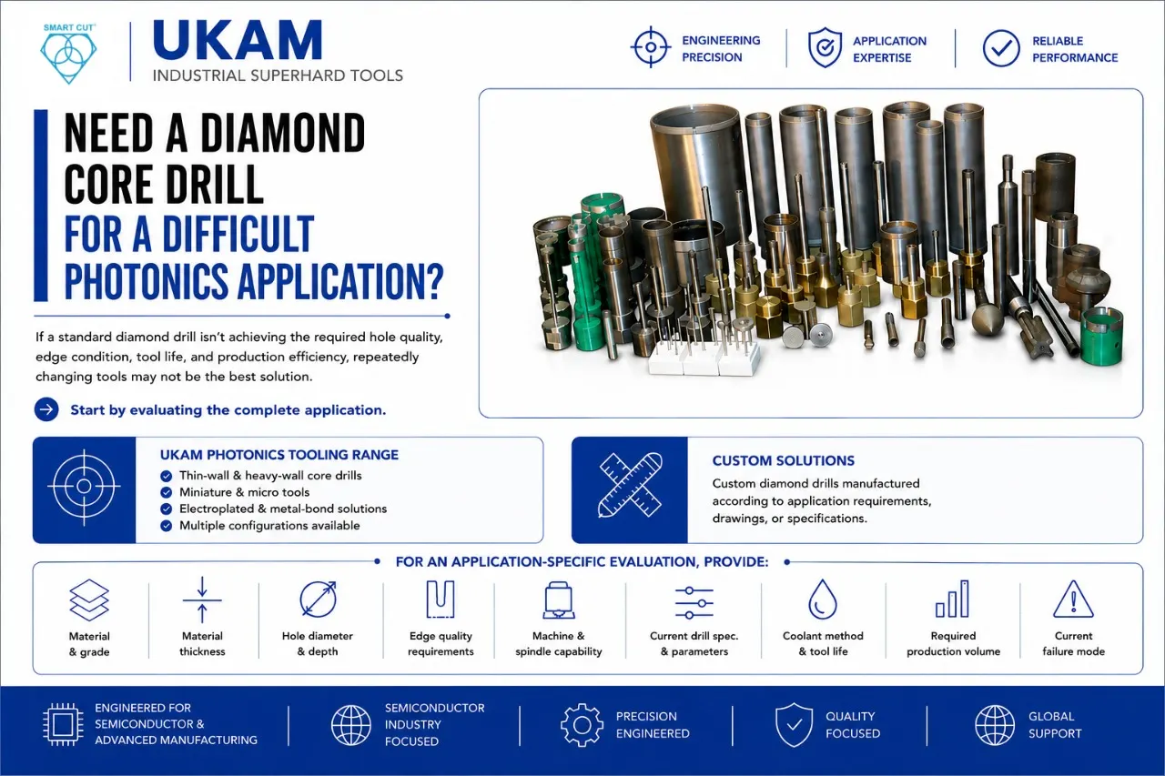
For an application-specific evaluation, provide: material and grade, material thickness, required hole diameter, hole depth, through or blind hole, diameter tolerance, surface-finish requirement, entry and exit edge requirements, machine type, spindle capability, current drill specification, current drilling parameters, coolant method, current tool life, required production volume, current failure mode, and photos or measurements of the hole, if available.
This information allows the drilling solution to be considered around the actual manufacturing requirement rather than around diameter alone.
The goal is not simply to select a diamond drill. It is to develop a drilling solution matched to the material, hole geometry, machine, quality requirements, and production objective.
Trusted by Tens of Thousands of Manufacturers, Laboratories,
Research Institutions Worldwide Since 1990
American Based Manufacturer
Established in 1990
