Glass Cutting Tools for Stained Glass: Engineering Guide for Hobbyists and Industrial Glass Manufacturers

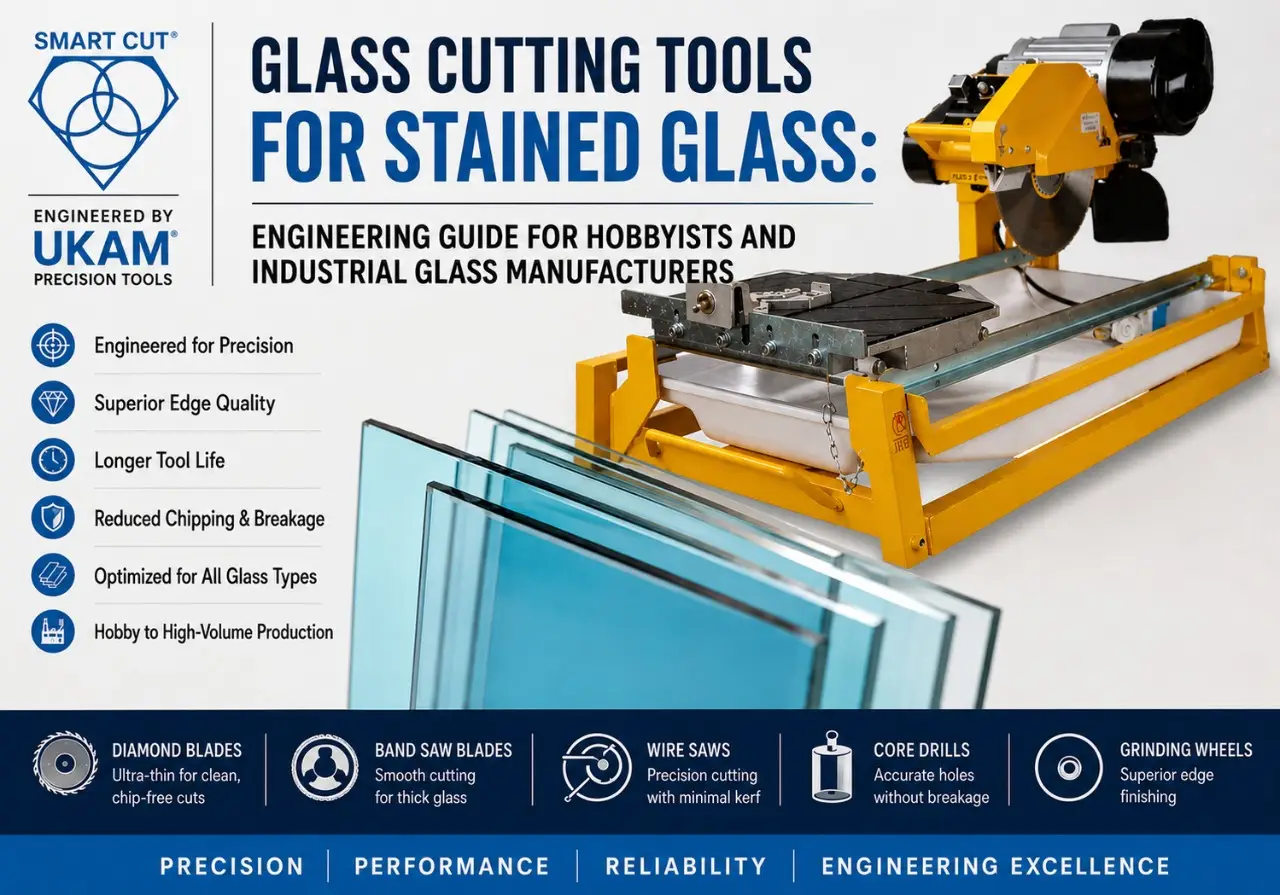
Table of Contents
Toggle
American Based Manufacturer

Established in 1990


Custom manufacturing


Engineering Problem
Glass behaves differently from most engineering materials. Although it appears rigid and dimensionally stable, it is highly sensitive to tensile stress, localized heat, vibration, and improper cutting forces. A small variation in tool selection or machine setup can result in edge chipping, microcracks, poor dimensional accuracy, excessive kerf loss, or complete part failure.
For hobbyists creating stained glass artwork, selecting the wrong cutting tool often results in uneven score lines, uncontrolled breaks, wasted material, and additional grinding. For manufacturers producing architectural glass, optical components, laboratory equipment, or electronic substrates, improper tool selection can increase scrap rates, reduce throughput, shorten tool life, and significantly raise production costs.
Many production issues are incorrectly attributed to spindle speed, feed rate, coolant delivery, or operator technique. While these variables certainly influence cutting performance, experienced applications engineers at UKAM Industrial Superhard Tools understand that successful glass machining begins with selecting the correct cutting technology for the material and manufacturing objective.
The ideal cutting solution depends on several engineering variables, including:
- Glass type and composition
- Material thickness
- Required dimensional tolerance
- Edge quality requirements
- Production volume
- Cutting geometry
- Machine capability
- Secondary finishing operations
A handheld glass cutter may be the appropriate choice for decorative stained glass panels, while precision optical glass, borosilicate components, quartz substrates, or laminated architectural glass often require advanced diamond cutting systems capable of maintaining tight tolerances and consistent surface integrity.
Rather than asking “What is the best glass cutting tool?”, the more appropriate engineering question is: “Which cutting technology is best suited for my material, application, and production requirements?”
This guide answers that question by comparing the most common glass cutting technologies, explaining when each should be used, and helping both hobbyists and industrial manufacturers select the right solution for their specific application.
Who Is This Guide For?
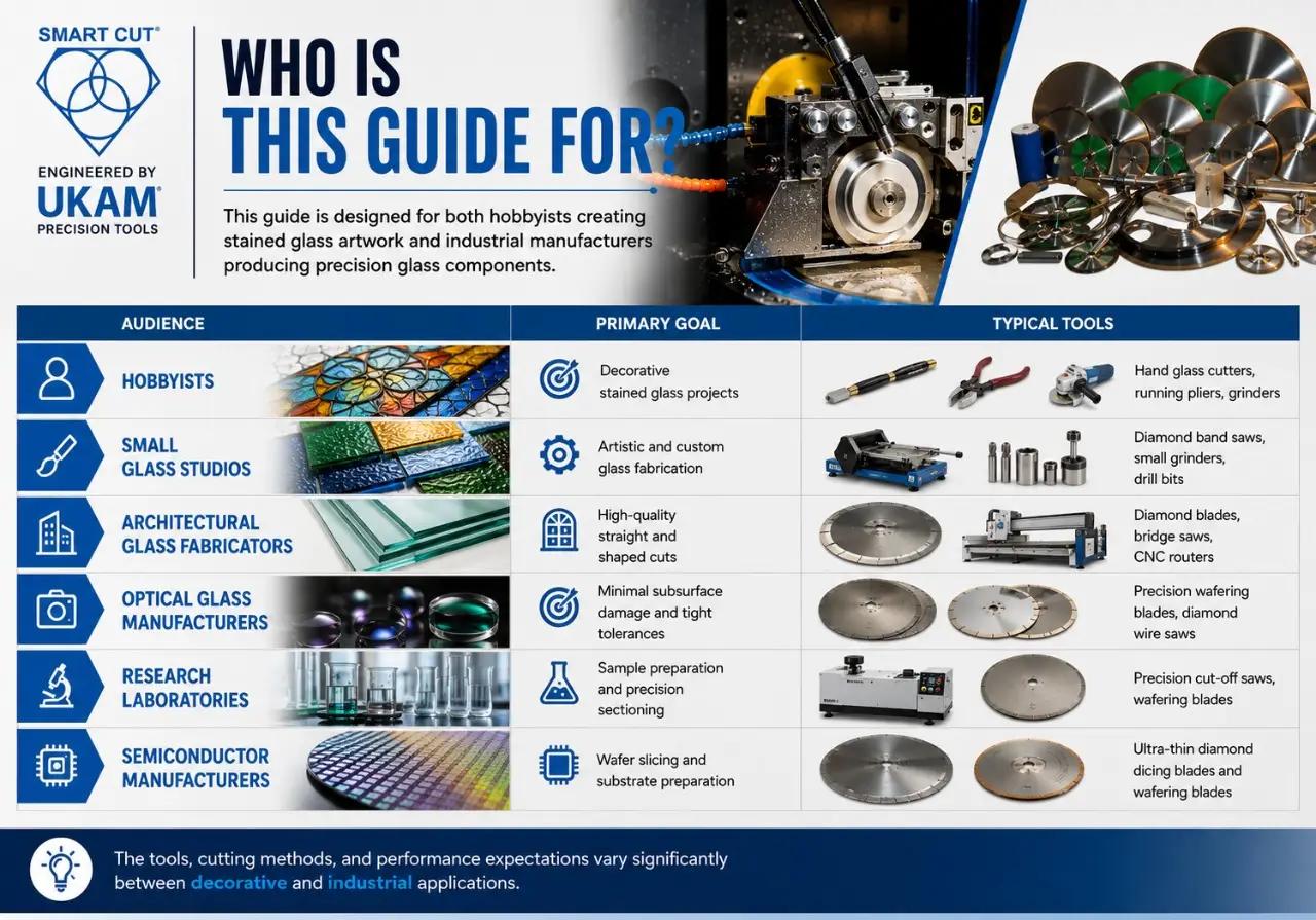
One of the most common reasons glass cutting articles fail is that they try to serve every audience with the same information. Someone creating a stained glass window at home has very different requirements than a manufacturing engineer producing optical components or semiconductor substrates.
To address both search intent and practical engineering needs, this guide separates decorative stained glass applications from industrial precision glass processing.
|
Audience |
Primary Goal |
Typical Tools |
|---|---|---|
|
Hobbyists |
Decorative stained glass projects |
Hand glass cutters, running pliers, grinders |
|
Small Glass Studios |
Artistic and custom glass fabrication |
Diamond band saws, small grinders, drill bits |
|
Diamond concentration |
Standard offerings |
Multiple concentration options |
|
Architectural Glass Fabricators |
High-quality straight and shaped cuts |
Diamond blades, bridge saws, CNC routers |
|
Optical Glass Manufacturers |
Minimal subsurface damage and tight tolerances |
Precision wafering blades, diamond wire saws |
|
Research Laboratories |
Sample preparation and precision sectioning |
Precision cut-off saws, wafering blades |
|
Semiconductor Manufacturers |
Wafer slicing and substrate preparation |
Ultra-thin diamond dicing blades and wafering blades |
This distinction is important because the tools, cutting methods, and performance expectations vary significantly between decorative and industrial applications.
Hobby Stained Glass vs. Industrial Glass Manufacturing
Although both applications involve cutting glass, the similarities largely end there. The objectives, equipment, tolerances, and process requirements are fundamentally different.
Hobby Stained Glass
Stained glass artists typically work with relatively thin decorative glass to create windows, lamps, mosaics, and artistic panels. Their priorities include ease of use, affordability, and the ability to produce curved or intricate shapes by hand.
Common tools include:
- Handheld glass cutters
- Running pliers
- Breaking pliers
- Glass grinders
- Small diamond band saws
- Diamond drill bits for decorative holes
Minor edge chips are often removed during grinding, and dimensional tolerances are generally less critical than appearance.
Industrial Glass Manufacturing
Industrial glass processing focuses on precision, repeatability, and production efficiency. Manufacturers may process:
- Optical glass
- Borosilicate glass
- Quartz
- Fused silica
- Display glass
- Laminated safety glass
- Scientific glass
- Semiconductor substrates
Unlike decorative work, industrial applications often require:
- Tight dimensional tolerances
- Minimal edge chipping
- Controlled kerf width
- Low subsurface damage
- High production throughput
- Documented process qualification
- Consistent quality across thousands of parts
To achieve these requirements, manufacturers typically use advanced diamond cutting technologies rather than manual scoring tools.
Examples include:
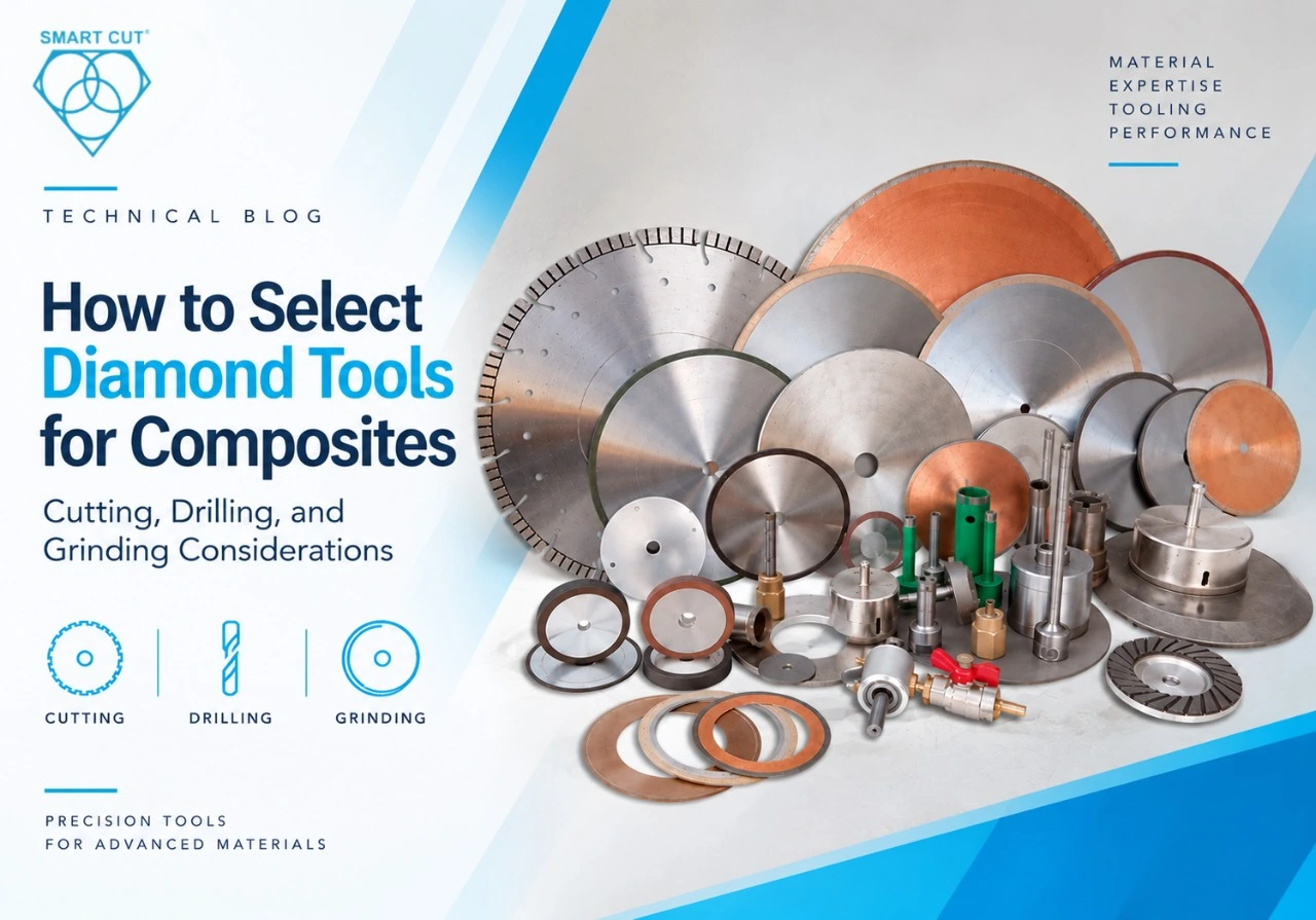
- SMART CUT® Ultra-Thin Diamond Cut-Off Blades for precision straight cuts.
- SMART CUT® Diamond Band Saw Blades for contour cutting and complex shapes.
- SMART CUT® Diamond Wire Saws for minimizing material loss in brittle materials.
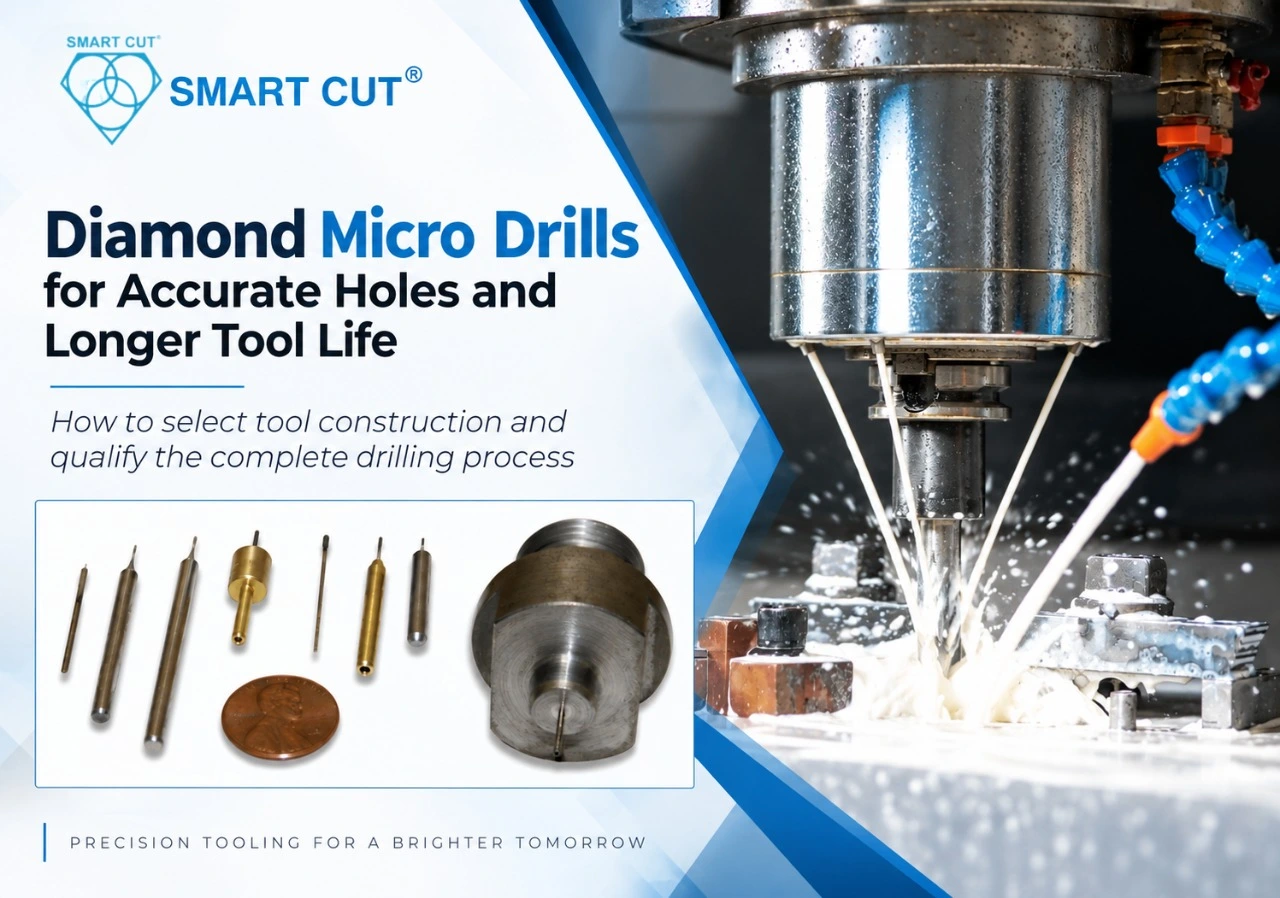
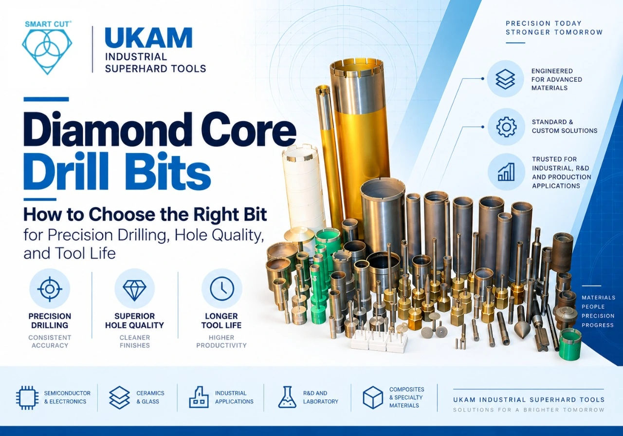
- SMART CUT® Diamond Core Drills for producing precise holes with minimal breakout.
- SMART CUT® Diamond Routers for edge profiling and contour machining.
Need help selecting the right cutting tool? If your application involves specialty glass, optical materials, ceramics, or other difficult-to-machine materials, a UKAM Applications Engineer can review your material specifications and recommend an appropriate cutting solution before production begins.
Why Selecting the Right Glass Cutting Tool Matters
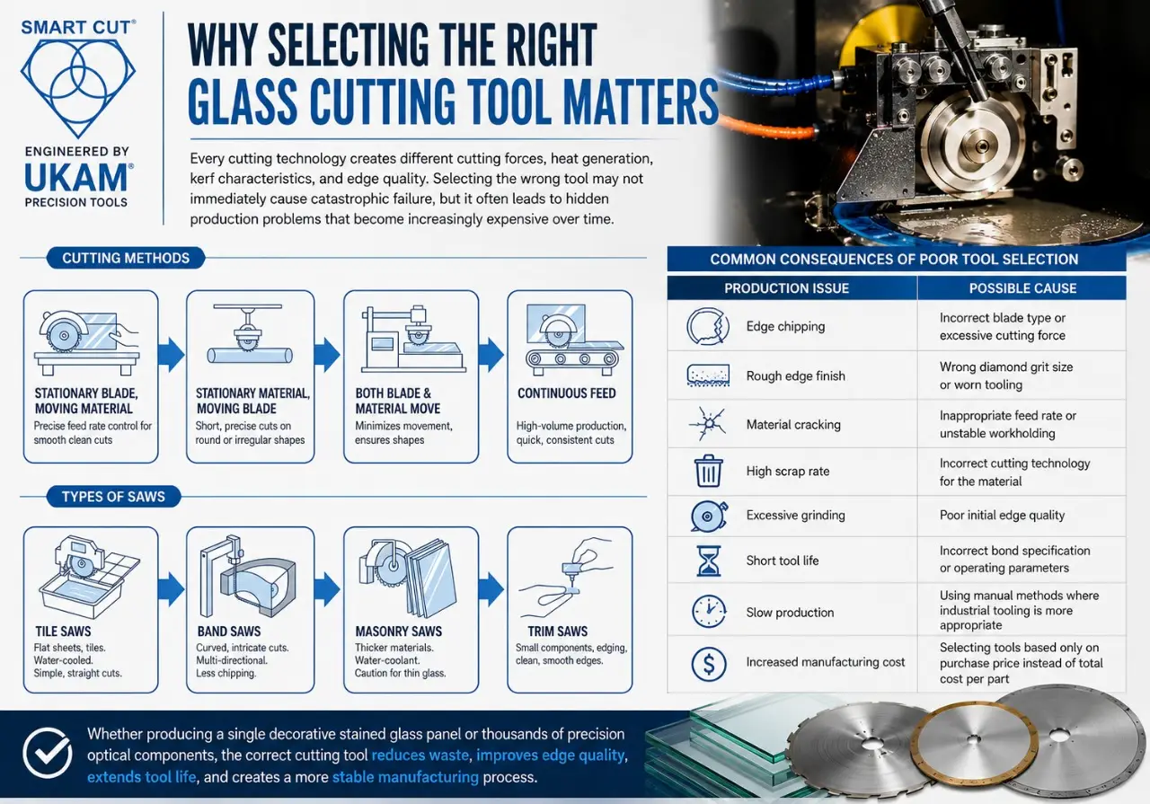
Every cutting technology creates different cutting forces, heat generation, kerf characteristics, and edge quality. Selecting the wrong tool may not immediately cause catastrophic failure, but it often leads to hidden production problems that become increasingly expensive over time.
|
Production Issue |
Possible Cause |
|---|---|
|
Edge chipping |
Incorrect blade type or excessive cutting force |
|
Rough edge finish |
Wrong diamond grit size or worn tooling |
|
Material cracking |
Inappropriate feed rate or unstable workholding |
|
High scrap rate |
Incorrect cutting technology for the material |
|
Excessive grinding |
Poor initial edge quality |
|
Short tool life |
Incorrect bond specification or operating parameters |
|
Slow production |
Using manual methods where industrial tooling is more appropriate |
|
Increased manufacturing cost |
Selecting tools based only on purchase price instead of total cost per part |
Whether producing a single decorative stained glass panel or thousands of precision optical components, the correct cutting tool reduces waste, improves edge quality, extends tool life, and creates a more stable manufacturing process.
Selecting the Right Glass Cutting Tool by Glass Type
Not all glass materials respond to cutting forces in the same way. Differences in composition, hardness, brittleness, thermal expansion, and internal stress require different tooling strategies and qualification methods.
One of the most common engineering mistakes is assuming that a diamond blade that performs well on one glass material will produce similar results on another. Even materials that appear visually similar—such as borosilicate and fused silica—can require different bond systems, diamond grit sizes, and operating parameters.
The following sections outline engineering considerations for the most common glass materials processed in decorative, laboratory, architectural, and industrial manufacturing environments.
Stained Glass
Stained glass is one of the oldest decorative materials and remains widely used in artistic panels, windows, lamps, mosaics, and architectural restoration. Most stained glass is relatively thin and designed for manual fabrication rather than automated manufacturing.
For hobbyists and small studios, handheld scoring tools remain the preferred solution because they are inexpensive, easy to use, and capable of producing accurate score lines on thin glass sheets.
However, as project complexity increases, manual scoring becomes less practical. Curved designs, thick decorative glass, and production work often benefit from diamond-powered cutting equipment.
Engineering Characteristics
- Thin decorative glass
- Moderate hardness
- Brittle fracture behavior
- Manual processing
- Low production volume
Recommended Cutting Tools
|
Application |
Recommended Tool |
|---|---|
|
Straight decorative cuts |
Hand Glass Cutter |
|
Curved artwork |
SMART CUT® Diamond Band Saw Blade |
|
Internal holes |
SMART CUT® Diamond Core Drill |
|
Edge finishing |
Diamond Grinding Wheel |
|
Intricate contours |
SMART CUT® Diamond Router |
- Establish documented dressing intervals.
- Inspect wheel condition routinely.
- Record dressing observations during qualification.
- Compare wheel condition before and after dressing.
Common Mistakes
- Applying excessive pressure during scoring
- Attempting multiple passes over the same score line
- Using dull scoring wheels
- Breaking glass too far from the score line
- Skipping edge grinding before assembly
Need help selecting the right diamond tool for decorative or production glass fabrication? See the Knowledge Center for application-specific guidance.
Borosilicate Glass
Borosilicate glass is commonly used for laboratory equipment, scientific instruments, pharmaceutical manufacturing, and chemical processing because of its excellent thermal stability and chemical resistance.
Although more resistant to thermal shock than standard glass, borosilicate remains brittle and requires controlled cutting forces to prevent edge damage.
Engineering Characteristics
- High thermal resistance
- Excellent chemical durability
- Moderate brittleness
- Precision laboratory applications
Recommended UKAM Products
- SMART CUT® Precision Diamond Cut-Off Blades
- SMART CUT® Diamond Core Drills
- SMART CUT® Diamond Grinding Wheels
Engineering Considerations
- Maintain continuous coolant flow.
- Avoid excessive feed rates.
- Inspect for edge microcracks before assembly.
- Verify spindle runout before qualification.
Common Manufacturing Problems
|
Problem |
Engineering Cause |
|---|---|
|
Edge chipping |
Excessive feed rate |
|
Thermal cracking |
Poor coolant application |
|
Rough edge finish |
Incorrect grit selection |
|
Premature blade wear |
Incorrect bond selection |
Internal Link Opportunity: Diamond Coolant Guide | Diamond Bond Selection Guide
Optical Glass
Optical glass manufacturing demands some of the highest quality standards in precision machining. Surface integrity, edge quality, and dimensional accuracy directly influence optical performance.
Even small defects introduced during cutting can increase polishing time or reduce component quality.
Engineering Characteristics
- Extremely high dimensional requirements
- Minimal subsurface damage
- Precision edge quality
- High-value material
Recommended UKAM Products
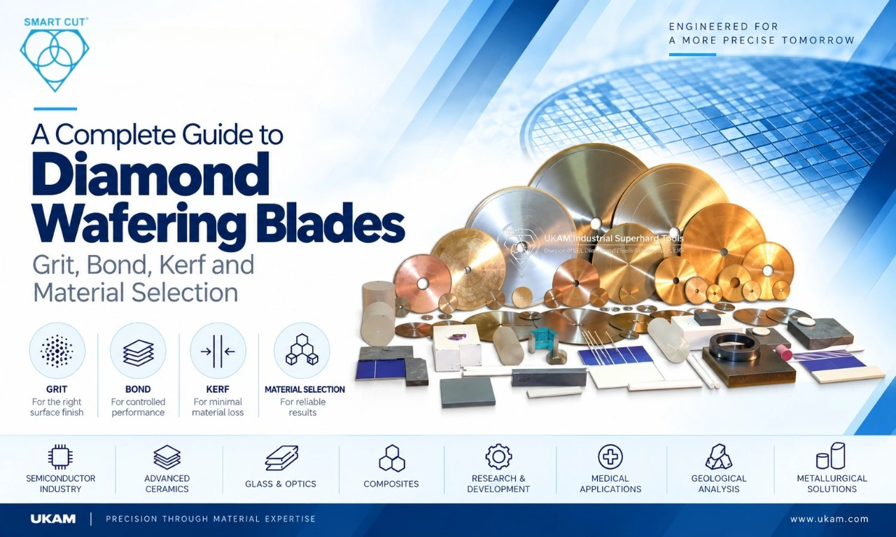
- SMART CUT® Wafering Blades
- SMART CUT® Diamond Wire Saw Systems
- SMART CUT® Diamond Grinding Wheels
Engineering Priorities
- Fine diamond grit
- Stable machine rigidity
- Continuous coolant delivery
- Low cutting forces
- Controlled spindle speed
Common Manufacturing Problems
- Edge breakout
- Subsurface cracking
- Surface scratches
- Kerf variation
Optical manufacturers typically prioritize surface quality over maximum production speed. Fine finishing is frequently completed with diamond lapping discs to bring surfaces within final flatness and Ra tolerances.
Quartz
Quartz is widely used in semiconductor manufacturing, laboratory equipment, UV optics, and electronics because of its excellent thermal stability and electrical insulation. It is one of the more demanding materials covered in UKAM’s glass and quartz core drilling application guidance.
However, quartz fractures easily under localized stress and requires careful process control.
Engineering Characteristics
- High hardness
- Brittle fracture
- Excellent thermal stability
- Difficult-to-machine material
Recommended UKAM Products
- SMART CUT® Diamond Wire Saws
- SMART CUT® Precision Diamond Blades
- SMART CUT® Diamond Core Drills
Engineering Recommendations
- Use lower cutting forces.
- Maintain consistent coolant coverage.
- Verify blade condition regularly.
- Avoid aggressive feed rates.
Fused Silica
Although often grouped with quartz, fused silica behaves differently during machining due to its unique manufacturing process and optical properties.
Applications include:
- Semiconductor equipment
- Laser optics
- Aerospace optics
- Aerospace optics
Engineering Priorities
- Reduce subsurface damage.
- Minimize polishing requirements.
- Maintain dimensional stability.
- Control heat generation.
Recommended UKAM Products
- SMART CUT® Wafering Blades
- SMART CUT® Diamond Wire Saw Systems
Laminated Glass
Laminated safety glass consists of multiple glass layers bonded together with an interlayer, typically polyvinyl butyral (PVB). This construction improves safety but complicates machining because the tool must cut both brittle glass and flexible polymer.
Engineering Characteristics
- Multi-layer construction
- Variable cutting resistance
- Heat-sensitive interlayer
Recommended UKAM Products
- SMART CUT® Diamond Cut-Off Blades
- SMART CUT® Diamond Routers
Common Challenges
|
Manufacturing Issue |
Possible Cause |
|---|---|
|
Delamination |
Excessive heat generation |
|
Edge chipping |
Incorrect blade specification |
|
Polymer smearing |
Inadequate coolant |
|
Poor edge quality |
Excessive feed rate |
Architectural Glass
Architectural glass fabrication emphasizes productivity, dimensional accuracy, and aesthetic edge quality. Manufacturers frequently process large sheets for commercial buildings, storefronts, curtain walls, and interior applications.
Engineering Objectives
- High throughput
- Repeatable edge quality
- Low scrap rate
- Efficient secondary finishing
Recommended UKAM Products
- SMART CUT® Diamond Blades
- SMART CUT® Diamond Routers
- SMART CUT® Diamond Grinding Wheels
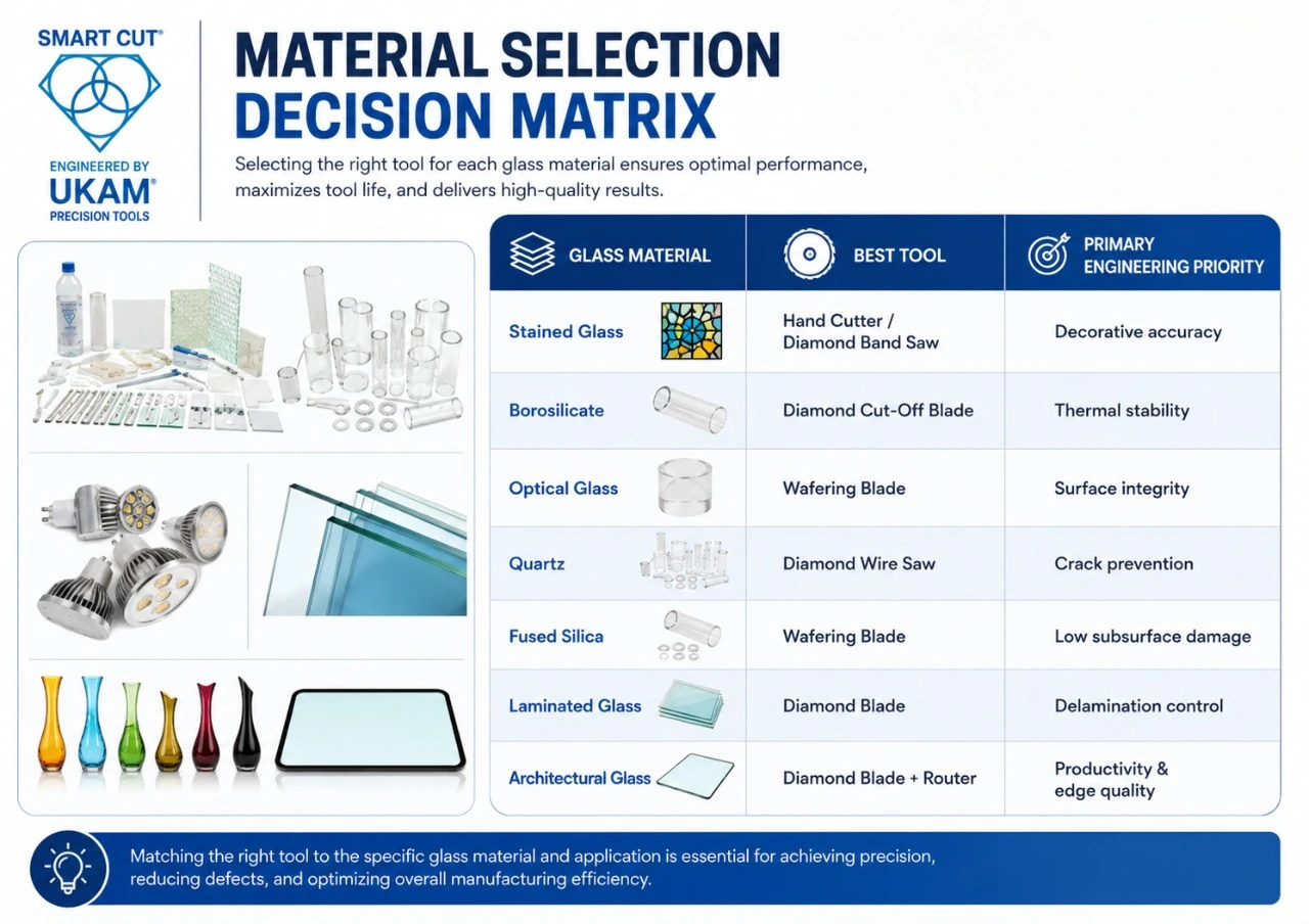
Material Selection Decision Matrix
|
Glass Material |
Best Tool |
Primary Engineering Priority |
|---|---|---|
|
Stained Glass |
Hand Cutter / Diamond Band Saw |
Decorative accuracy |
|
Borosilicate |
Diamond Cut-Off Blade |
Thermal stability |
|
Optical Glass |
Wafering Blade |
Surface integrity |
|
Quartz |
Diamond Wire Saw |
Crack prevention |
|
Fused Silica |
Wafering Blade |
Low subsurface damage |
|
Laminated Glass |
Diamond Blade |
Delamination control |
|
Architectural Glass |
Diamond Blade + Router |
Productivity & edge quality |
Engineering Tip
Do not qualify one diamond tool across multiple glass materials simply because the hardness appears similar. Each material has unique fracture characteristics, thermal behavior, and edge-quality requirements. Conduct a separate qualification process for every new glass type to optimize tool life, reduce scrap, and maintain consistent production quality.
Selecting the correct glass cutting tool is only the beginning of a successful manufacturing process. Even the best diamond blade or wire saw will underperform if it is installed on an unstable machine, operated with incorrect parameters, or applied to a material without proper qualification.
Professional manufacturers do not qualify tooling through trial and error. Instead, they follow a documented engineering process that evaluates tooling, machine capability, operating parameters, and finished part quality before releasing the process to production.
Whether you are producing decorative architectural glass, laboratory components, optical substrates, or semiconductor materials, a structured qualification process minimizes risk, improves repeatability, and reduces manufacturing costs.
Six-Step Engineering Qualification Workflow
The following workflow can be used when introducing a new diamond cutting tool, changing materials, or optimizing an existing glass cutting process.
Phase 1 — Define the Manufacturing Objective
Every qualification project should begin by clearly identifying the production goal. Typical objectives include:
- Reduce edge chipping
- Improve surface finish
- Increase tool life
- Reduce polishing time
- Increase production throughput
- Improve dimensional accuracy
- Reduce cost per part
- Minimize kerf loss
Phase 2 — Evaluate the Glass Material
Every glass material behaves differently during machining. Before selecting tooling, document:
|
Material Parameter |
Record |
|---|---|
|
Glass Type |
Stained, Borosilicate, Quartz, Optical, etc. |
|
Thickness |
Actual thickness |
|
Hardness |
Material specification |
|
Surface Finish Requirement |
Customer requirement |
|
Tolerance |
Dimensional requirement |
|
Production Volume |
Prototype or production |
|
Secondary Operations |
Grinding, polishing, coating |
Never assume one blade specification can successfully machine every glass material.
Phase 3 — Select the Appropriate Diamond Tool
Tool selection should always match the manufacturing objective.
Engineering Decision Matrix
|
Manufacturing Requirement |
Recommended UKAM Solution |
|---|---|
|
Straight precision cuts |
SMART CUT® Ultra-Thin Diamond Cut-Off Blades |
|
Curved profiles |
SMART CUT® Diamond Band Saw Blades |
|
Minimal kerf loss |
SMART CUT® Diamond Wire Saw Systems |
|
Precision holes |
SMART CUT® Diamond Core Drills |
|
Edge profiling |
SMART CUT® Diamond Routers |
|
Secondary finishing |
SMART CUT® Diamond Grinding Wheels |
Need help selecting the right tool? Browse the full UKAM product catalog or upload your drawing and application details for a tailored recommendation.
Phase 4 — Verify Machine Capability
Many production issues are incorrectly blamed on tooling when the root cause is machine instability. Before production trials, inspect:
- Spindle runout
- Machine rigidity
- Blade mounting
- Flange condition
- Coolant delivery
- Workholding
- Feed mechanism
- Machine vibration
Machine qualification should always precede tooling qualification.
Phase 5 — Conduct Controlled Production Trials
Production trials should be performed under documented operating conditions. Record:
- RPM
- Feed rate
- Coolant type
- Coolant flow
- Blade specification
- Material batch
- Operator
- Machine
Change only one major variable at a time. Changing feed rate, RPM, coolant, and blade simultaneously makes troubleshooting almost impossible.
Phase 6 — Inspection & Production Approval
Qualification is complete only after repeated production trials consistently meet quality requirements. Inspect:
- Surface finish
- Edge chipping
- Kerf width
- Tool wear
- Cycle time
- Repeatability
- Dimensional accuracy
Approved operating parameters should then become the production standard.
Process Optimization Checklist
Qualification should not end once the first acceptable part is produced. Continuous process improvement helps reduce manufacturing cost while extending tool life.
Areas to Monitor
- Tool wear
- Coolant condition
- Blade loading
- Machine vibration
- Spindle condition
- Edge quality
- Production throughput
- Scrap rate
Documenting these trends allows engineers to identify gradual process changes before they affect production quality.
Engineering Troubleshooting Guide
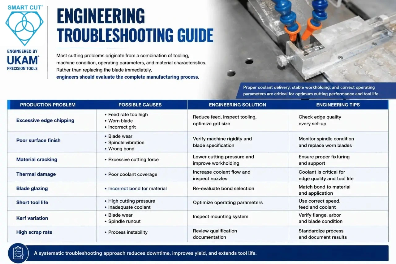
Most cutting problems originate from a combination of tooling, machine condition, operating parameters, and material characteristics. Rather than replacing the blade immediately, engineers should evaluate the complete manufacturing process — see the full Troubleshooting Guide for a detailed diagnostic reference.
|
Production Problem |
Possible Causes |
Engineering Solution |
|---|---|---|
|
Excessive edge chipping |
Feed rate too high, worn blade, incorrect grit |
Reduce feed, inspect tooling, optimize grit size |
|
Poor surface finish |
Blade wear, spindle vibration, wrong bond |
Verify machine rigidity and blade specification |
|
Material cracking |
Excessive cutting force |
Lower cutting pressure and improve workholding |
|
Thermal damage |
Poor coolant coverage |
Increase coolant flow and inspect nozzles |
|
Blade glazing |
Incorrect bond for material |
Re-evaluate bond selection |
|
Short tool life |
High cutting pressure, inadequate coolant |
Optimize operating parameters |
|
Kerf variation |
Blade wear or spindle runout |
Inspect mounting system |
|
High scrap rate |
Process instability |
Review qualification documentation |
Engineering Comparison Charts
Diamond Blade vs. Diamond Wire Saw
|
Feature |
Diamond Blade |
Diamond Wire Saw |
|---|---|---|
|
Straight Cuts |
Excellent |
Excellent |
|
Curved Cuts |
Limited |
Limited |
|
Kerf Width |
Low |
Very Low |
|
Material Loss |
Low |
Lowest |
|
Cutting Force |
Moderate |
Low |
|
Optical Glass |
Excellent |
Excellent |
|
Thick Materials |
Good |
Excellent |
Metal Bond vs. Resin Bond
| Resin Bond | Metal Bond |
|---|---|
|
Better surface finish |
Longer tool life |
|
Lower cutting forces |
Better wear resistance |
|
Excellent for fragile glass |
Excellent for production environments |
|
Faster self-sharpening |
Improved profile retention. |
Electroplated vs. Sintered Diamond Tools
|
Electroplated |
Sintered |
|---|---|
|
Single abrasive layer |
Multiple abrasive layers |
|
Lower initial cost |
Longer service life |
|
High cutting efficiency |
Better long-term economics |
|
Excellent for specialty work |
Excellent for production |
Electroplated tools use a single abrasive layer, carry a lower initial cost, offer high cutting efficiency, and suit specialty work. Sintered tools use multiple abrasive layers, offer a longer service life, better long-term economics, and are excellent for production.
Hand Tools vs. Industrial Diamond Tools
|
Hand Tools |
Industrial Diamond Tools |
|---|---|
|
Hobby use |
Manufacturing |
|
Manual operation |
Machine controlled |
|
Decorative projects |
Production environments |
|
Limited accuracy |
High precision |
|
Low production volume |
High production volume |
Cost Per Part Engineering
Many purchasing decisions focus only on the initial cost of a cutting tool. Experienced manufacturing engineers evaluate total cost per part instead.
Factors Affecting Cost Per Part
- Tool purchase price
- Tool life
- Machine downtime
- Scrap rate
- Edge quality
- Polishing requirements
- Operator intervention
- Production throughput
Illustrative Example
|
Factor |
Tool A |
SMART CUT® Tool |
|---|---|---|
|
Initial Cost |
Lower |
Higher |
|
Tool Life |
Moderate |
Longer |
|
Scrap Rate |
Higher |
Lower |
|
Surface Finish |
Moderate |
Excellent |
|
Production Downtime |
Higher |
Lower |
|
Cost Per Part |
Higher |
Lower |
Illustrative example only. Actual production costs depend on material, machine capability, and operating conditions.
Recommended Engineering Illustrations
This article should include the following supporting graphics:
- Glass Cutting Technology Selection Flowchart
- Diamond Blade Cross-Section
- Diamond Wire Saw Operation Diagram
- Bond Structure Comparison (Resin vs. Metal)
- Diamond Grit Size Comparison
- Kerf Width Comparison
- Edge Chipping (Good vs. Poor)
- Coolant Flow Diagram
- Machine Setup Illustration
- Production Qualification Workflow
Selecting the right glass cutting tool depends on more than the material alone. Machine capability, production volume, dimensional tolerances, and downstream finishing all influence tooling performance. If you’re unsure which solution best fits your application, submit your material specifications or drawings to a UKAM Applications Engineer for a customized tooling recommendation before beginning production.
Selecting a diamond cutting tool is not the final step in achieving a stable manufacturing process. Long-term production success depends on working with an engineering partner that understands material behavior, machining challenges, and process optimization — not simply a supplier that sells tooling.
For manufacturers processing glass, ceramics, composites, semiconductors, and other advanced materials, technical support, application knowledge, and process qualification are often just as valuable as the cutting tool itself.
Engineering Guide to Evaluating a Diamond Tool Supplier
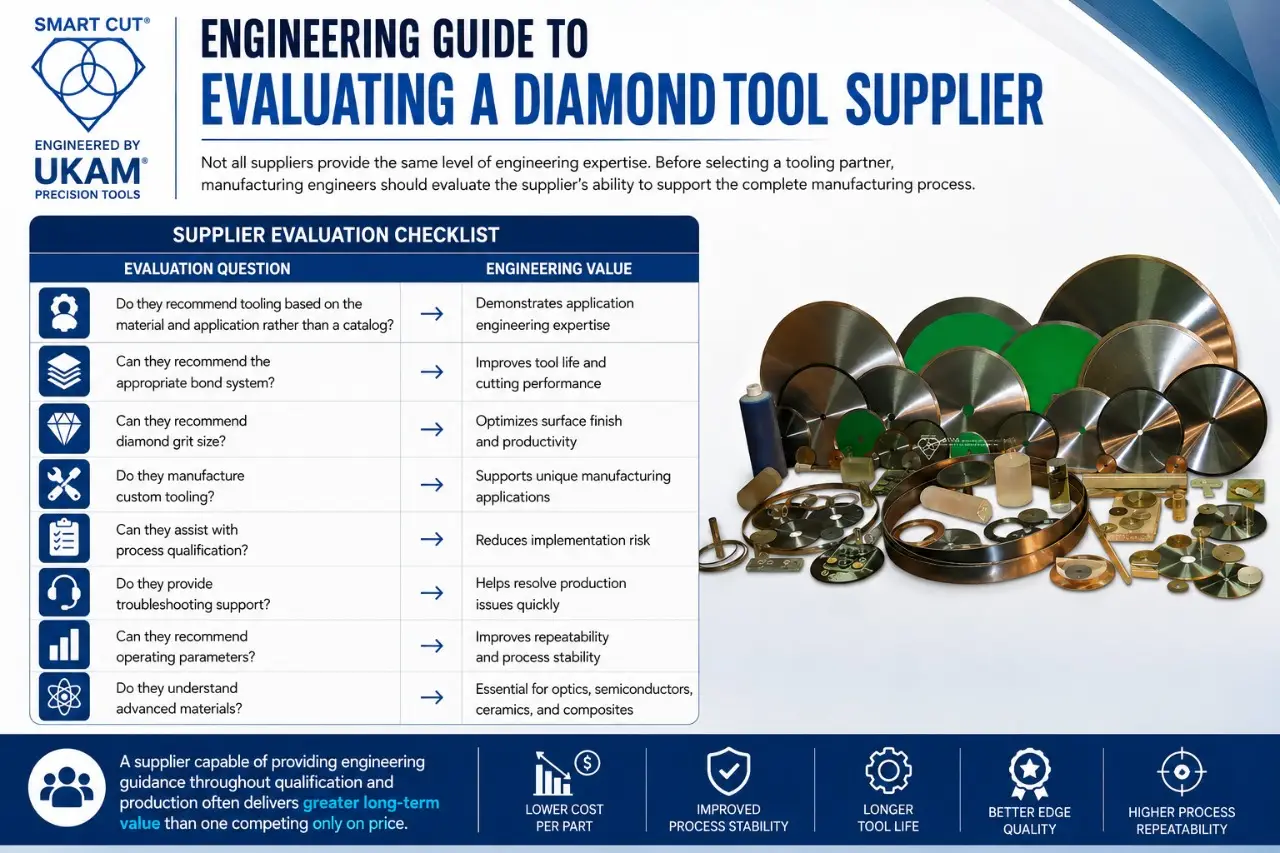
Not all suppliers provide the same level of engineering expertise. Before selecting a tooling partner, manufacturing engineers should evaluate the supplier’s ability to support the complete manufacturing process.
Supplier Evaluation Checklist
|
Evaluation Question |
Engineering Value |
|---|---|
|
Do they recommend tooling based on material and application rather than a catalog? |
Demonstrates application engineering expertise |
|
Can they recommend the appropriate bond system? |
Improves tool life and cutting performance |
|
Can they recommend diamond grit size? |
Optimizes surface finish and productivity |
|
Do they manufacture custom tooling? |
Supports unique manufacturing applications |
|
Can they assist with process qualification? |
Reduces implementation risk |
|
Do they provide troubleshooting support? |
Helps resolve production issues quickly |
|
Can they recommend operating parameters? |
Improves repeatability and process stability |
|
Do they understand advanced materials? |
Essential for optics, semiconductors, ceramics, and composites |
A supplier capable of providing custom diamond tool manufacturing and engineering guidance throughout qualification and production often delivers greater long-term value than one competing only on price.
Recommended UKAM Products by Application
Selecting the appropriate cutting technology depends on the workpiece material, production objectives, and required quality level.
|
Application |
Recommended UKAM Product |
|---|---|
|
Straight precision glass cutting |
SMART CUT® Ultra-Thin Diamond Cut-Off Blades |
|
Curved stained glass fabrication |
SMART CUT® Diamond Band Saw Blades |
|
Optical glass processing |
SMART CUT® Wafering Blades |
|
Quartz and fused silica |
SMART CUT® Diamond Wire Saw Systems |
|
Hole drilling |
SMART CUT® Diamond Core Drills |
|
Edge profiling |
SMART CUT® Diamond Routers |
|
Secondary edge finishing |
SMART CUT® Diamond Grinding Wheels |
|
Production grinding |
Diamond & CBN Grinding Wheels |
These recommendations should always be verified through process qualification and adjusted to the specific material, machine capability, and production requirements
Downloadable Engineering Resources
To support process planning and qualification, manufacturers may find the following resources valuable:
- Diamond Tool Selection Worksheet
- Glass Cutting Process Qualification Checklist
- Diamond Tool Selection Guide
- Diamond Grit Size Guide
- Process Validation Worksheet
- Cost Per Part Evaluation Sheet
- Supplier Evaluation Checklist
- Diamond Concentration Guide
- Engineering Trial Report Template
- Preventive Maintenance Inspection Checklist
These resources can help standardize evaluations, improve documentation, and simplify future process optimization.
Engineering Note: This comparison is illustrative and does not represent measured production results. Actual manufacturing costs depend on material type, wheel specification, machine capability, coolant delivery, operator practices, and production requirements.
Silicon Carbide (SiC)
Silicon carbide is one of the most abrasive engineering ceramics processed with diamond wheels. As grinding continues, dull diamond particles may remain exposed while cutting efficiency gradually decreases.
Primary Failure Mode: Wheel glazing resulting in increased grinding forces and reduced material removal.
Common Causes
- Bond selection not matched to material abrasiveness.
- Dressing intervals extended beyond qualified limits.
- Reduced coolant coverage.
- Increasing spindle load ignored during production.
Engineering Recommendations
- Inspect wheel condition before replacing the wheel.
- Review dressing practices together with bond selection.
- Maintain consistent coolant delivery.
- Record grinding observations throughout qualification.
To support process planning and qualification, manufacturers may find the following resources valuable:
Alumina (Al₂O₃)
Alumina fractures in a brittle manner. Once glazing develops, grinding stability may decrease before obvious wheel wear becomes visible.
Primary Failure Mode: Surface finish deterioration accompanied by edge chipping.
Common Causes
- Delayed dressing.
- Incorrect grit selection.
- Process changes made without documentation.
Engineering Recommendations
- Monitor finished surface quality.
- Inspect abrasive exposure regularly.
- Review wheel specification before changing grinding parameters.
Silicon Nitride (Si₃N₄)
Silicon nitride generates relatively high grinding forces. Wheel glazing gradually increases spindle load as cutting efficiency declines.
Primary Failure Mode: Higher spindle load with decreasing stock removal.
Common Causes
- Worn abrasive remaining active.
- Poor coolant penetration.
- Dressing intervals not optimized.
Engineering Recommendations
- Monitor spindle behavior.
- Maintain consistent dressing.
- Inspect wheel condition throughout production.
Sapphire
Sapphire grinding requires stable abrasive exposure to maintain optical quality.
Primary Failure Mode: Thermal surface damage.
Common Causes
- Poor coolant delivery.
- Wheel glazing increasing grinding friction.
- Excessive grinding pressure.
Engineering Recommendations
- Verify coolant reaches the grinding interface.
- Review dressing practices.
- Inspect wheel before adjusting grinding parameters.
Fused Silica
Fused silica is susceptible to subsurface damage when grinding temperatures increase.
Primary Failure Mode: Microfracture beneath the finished surface.
Common Causes
- Delayed wheel maintenance.
- Poor coolant coverage.
- Reduced cutting efficiency caused by glazing.
Engineering Recommendations
- Maintain stable coolant delivery.
- Inspect wheel condition routinely.
- Review grit size and bond selection during qualification.
Tungsten Carbide
Tungsten carbide requires stable grinding conditions because high grinding forces accelerate wheel glazing.
Primary Failure Mode: Loss of cutting efficiency.
Common Causes
- Bond retaining worn abrasive too long.
- Machine vibration.
- Infrequent dressing.
Engineering Recommendations
- Monitor grinding forces.
- Inspect machine rigidity.
- Review bond selection if glazing develops repeatedly.
Gallium Arsenide (GaAs)
Gallium arsenide requires careful process control because of its brittle structure.
Primary Failure Mode: Surface fracture resulting from unstable grinding conditions.
Common Causes
- Increased grinding friction.
- Inconsistent coolant delivery.
- Delayed wheel inspection.
Engineering Considerations
- Monitor grinding consistency.
- Maintain wheel condition.
- Review qualification records before changing wheel specification.
Grinding PCD places significant demands on abrasive exposure and process stability.
Primary Failure Mode: Wheel glazing accompanied by increased grinding forces.
Common Causes
- Incorrect bond selection.
- Dressing delayed.
- Coolant delivery becoming inconsistent.
Engineering Considerations
- Review the complete wheel specification.
- Inspect abrasive exposure frequently.
- Maintain documented qualification procedures.
Troubleshooting Matrix
The following reference provides a structured method for identifying the most common causes of wheel glazing. For a step-by-step diagnostic walkthrough, see UKAM’s Diamond & CBN Wheel Troubleshooting Guide.
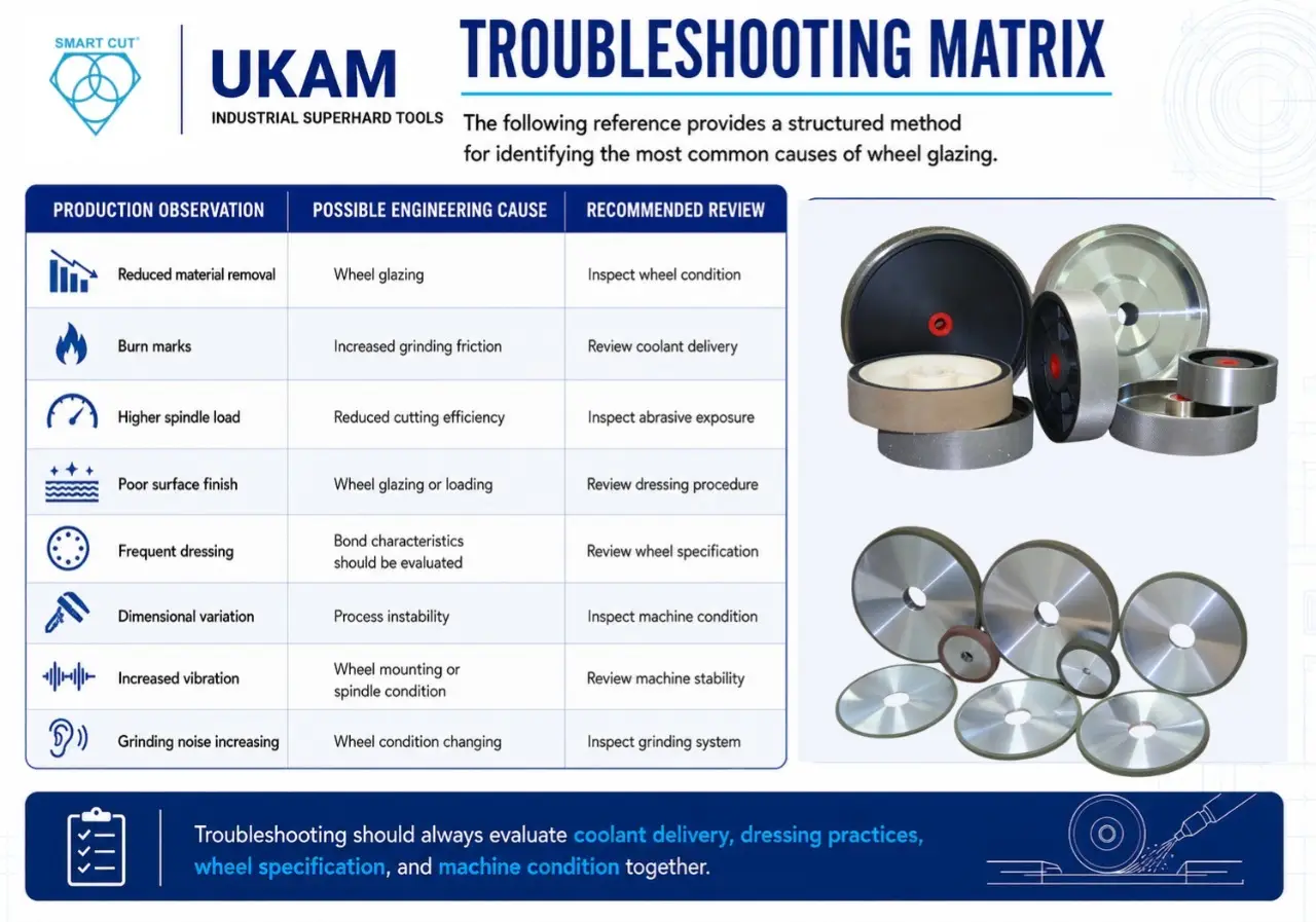
|
Production Observation |
Possible Engineering Cause |
Recommended Review |
|---|---|---|
|
Reduced material removal |
Wheel glazing |
Inspect wheel condition |
|
Burn marks |
Increased grinding friction |
Review coolant delivery |
|
Higher spindle load |
Reduced cutting efficiency |
Inspect abrasive exposure |
|
Poor surface finish |
Wheel glazing or loading |
Review dressing procedure |
|
Frequent dressing |
Bond characteristics should be evaluated |
Review wheel specification |
|
Dimensional variation |
Process instability |
Inspect machine condition |
|
Increased vibration |
Wheel mounting or spindle condition |
Review machine stability |
|
Grinding noise increasing |
Wheel condition changing |
Inspect grinding system |
Frequently Asked Questions
For hobby and decorative projects, a quality handheld glass cutter is typically the best starting point. For professional studios or production environments requiring greater precision, diamond band saws and precision diamond blades provide improved accuracy and repeatability.
Optical glass generally requires precision diamond wafering blades or diamond wire saw systems to minimize subsurface damage, improve edge quality, and reduce downstream polishing requirements.
No. Glass materials such as stained glass, borosilicate, quartz, fused silica, laminated glass, and optical glass each have different machining characteristics. Tool selection should always be based on the specific material and production objective.
Coolant reduces heat generation, improves tool life, flushes away debris, and helps maintain consistent cutting performance. Inadequate coolant delivery can increase edge chipping, thermal damage, and premature tool wear.
Reducing edge chipping typically requires evaluating several process variables, including blade specification, bond system, grit size, feed rate, spindle condition, machine rigidity, and coolant application. Adjusting only one variable rarely solves the underlying issue.
Diamond blades are generally preferred for straight precision cuts and higher production rates, while diamond wire saws generate lower cutting forces and reduced kerf loss, making them well suited for fragile or high-value materials.
Resin bonds are often selected when minimizing cutting forces and achieving a finer surface finish are priorities. Metal bonds typically offer greater wear resistance and are commonly used in higher-volume production environments. Final selection should be validated through process qualification.
Engineering assistance is recommended when introducing a new material, qualifying a production process, reducing edge chipping, improving surface finish, increasing tool life, lowering cost per part, or selecting tooling for a specialized application. Providing drawings, material specifications, machine details, and production goals enables more accurate recommendations.
Engineering Summary
Selecting the right glass cutting tool involves far more than choosing a blade from a catalog. Every application must balance material characteristics, cutting geometry, machine capability, dimensional tolerances, production volume, and cost objectives.
Decorative stained glass projects, architectural fabrication, laboratory glassware, optical components, semiconductor substrates, and advanced glass materials all require different cutting technologies and qualification strategies. Successful manufacturers document their processes, validate tooling through structured trials, and continuously optimize production based on measurable engineering data.
By combining appropriate diamond tooling with systematic process qualification — supported by resources such as the How to Properly Use Precision Diamond Blades guide, the Diamond Tools compared with Abrasive Tools article, and Process Development services — manufacturers can improve product quality, reduce scrap, extend tool life, and achieve more consistent production results.
For additional engineering guidance, readers should also review these UKAM technical resources:
Final Call to Action
Whether you’re producing decorative stained glass, architectural glass, laboratory components, optical assemblies, or precision industrial parts, selecting the right diamond cutting tool can significantly impact product quality, productivity, and manufacturing cost.
If you’re uncertain which tool is best for your application, consult a UKAM Applications Engineer. By reviewing your material, drawings, machine specifications, and production goals, UKAM can recommend an engineered solution tailored to your process — not just a standard catalog product.
Further Reading
- 5 Tips to Make Electroplated Diamond Wheels Last Longer
- Diamond Band Saw Blade Usage Recommendations & Best Practices
- Diamond Core Drills: The Complete Expert Guide
- Browse the UKAM Blog for ongoing engineering articles and application notes.
Trusted by Tens of Thousands of Manufacturers, Laboratories,
Research Institutions Worldwide Since 1990
American Based Manufacturer
Established in 1990
Custom manufacturing
RELATED ARTICLES