








































Diamond Core Drill Bits: How to Choose the Right Bit for Precision Drilling, Hole Quality, and Tool Life

Table of Contents
Toggle
American Based Manufacturer

Established in 1990


Custom manufacturing


Choosing a diamond core drill bit starts with the material, the finished hole, and the equipment that will produce it. Diameter matters, but two drills with the same nominal diameter can behave very differently. Their cutting-wall thickness, diamond grit, bond, usable depth, and mounting arrangement all influence the result.
An unsuitable specification can increase drilling force, chip the workpiece, produce oversized holes, or shorten tool life. Similar symptoms can also come from runout, poor support, or inadequate coolant delivery. Successful selection therefore requires a clear definition of both the tool and the process.
At UKAM Industrial Superhard Tools, we manufacture standard and custom diamond core drills for industrial, laboratory, research, construction, and specialty applications. We evaluate the relationship between material, geometry, machine capability, and production requirements when recommending a drill.
This guide explains how to prepare that information, compare tool designs, diagnose common problems, and evaluate cost per acceptable hole. It focuses on the decisions that help you move from a nominal drill size to a specification you can qualify.
Start with the application and acceptance requirements
A diamond core drill uses exposed diamond abrasive to remove an annular path through the workpiece. A conventional hollow design leaves a central core. This can reduce the amount of material removed compared with drilling the entire cross-section and can allow recovery of a useful sample.
Solid diamond drills remove material across their working face. Bottoming and non-core-forming tools address different hole geometries. Identify which result you need before comparing products. A hollow drill, a solid micro drill, and a bottoming tool should not be selected from diameter alone.
Glass, quartz, advanced ceramics, stone, semiconductor materials, and composites are common diamond-drilling applications. Their behavior differs substantially. Material grade, porosity, fillers, coatings, reinforcement, and condition can change the appropriate tooling strategy. For example, an unfired ceramic and a fully sintered ceramic require separate evaluations.
Begin your selection with six decisions.
Identify the material and its condition
Record the exact material designation when available. Include thickness, coatings, and any variation between production lots. Explain whether contamination, thermal exposure, or contact with coolant could affect the component. A general description such as ceramic or composite rarely provides enough information for a precise recommendation.
Define the finished hole and recovered core
Specify hole diameter, depth, location, and tolerances. State whether the hole is through or blind. Add limits for roundness, taper, surface finish, and entry or exit chipping where these affect acceptance. If the core is the desired product, specify its diameter and quality requirements separately.
Set the production objective
Identify the required quantity and expected repeat demand. Decide whether your main constraint is yield, cycle time, tool changes, or total cost. Define mandatory quality limits before using speed or tool price to rank alternatives.
Check the machine and setup
Record the machine type, available speed range, mounting interface, coolant method, and workholding arrangement. Include measured runout if available. A tool recommendation must fit the actual machine and its operating limits.
Select a complete tool specification
Evaluate bond, grit, cutting-wall thickness, depth, and rim configuration together. Record the resulting specification so a successful trial can be repeated. A nominal diameter and a description such as fine diamond do not fully define the tool.
Qualify the result
Measure hole quality throughout the trial. Record drilling time, accepted output, tool condition, and any intervention. Test representative material and confirm that performance remains acceptable as the tool wears.
Understand the dimensions that control the drilling result
The drill body, diamond cutting section, and produced hole have related dimensions. They are not necessarily identical. A drawing should identify which surface each dimension controls.
The finished cutting outside diameter describes the outer working envelope of the diamond section. It influences the hole diameter. The cutting inside diameter influences the remaining core diameter. Actual results also depend on abrasive protrusion, wear, mounted runout, deflection, and material removal behavior.
The supporting tube may have a different OD and ID from the cutting section. Relief between these surfaces can provide clearance around the body and the core. Do not substitute tube dimensions for finished cutting dimensions when comparing drills.
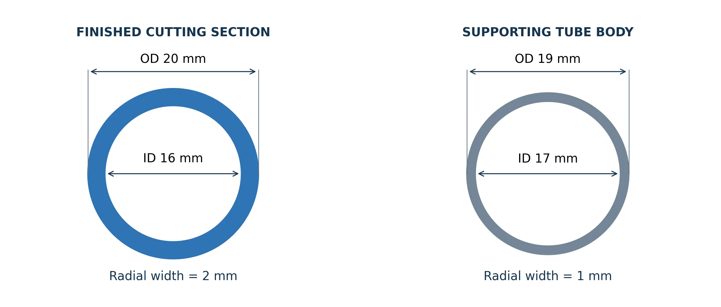
Illustrative end views. The finished cutting section and supporting tube can have different dimensions. These examples are not a product specification.
For a circular cutting section, radial cutting-wall thickness equals the finished cutting OD minus the finished cutting ID, divided by two. For the tube body, use the tube OD and tube ID in the same relationship.
For example, an illustrative cutting section with a 20 mm OD and 16 mm ID has a radial width of 2 mm. That calculation does not establish the tube wall thickness unless the tube has those same dimensions. It also does not guarantee a 20.000 mm finished hole.
For precision work, specify the tool dimensions and the required hole tolerance separately. Establish the relationship between them through a controlled trial. If you need a recovered core, inspect its dimensions independently of the hole.
Thin-wall and heavier-wall designs
A thinner cutting wall removes a narrower annular path. This can reduce material loss and cutting force in a suitable application. It can be valuable when drilling costly substrates, recovering samples, or controlling damage in brittle components.
The benefit depends on adequate stiffness, alignment, and support. A delicate tube or long unsupported section may become sensitive to side loading. Thin-wall selection should therefore include the machine, mounting length, usable depth, and workpiece support.
A thicker wall can provide more supporting material and a larger abrasive section. It also removes more workpiece material. The resulting force, heat, and power requirements must fit the process. Increasing thickness should address an identified problem, such as inadequate stiffness or wear allowance.
At a fixed 20 mm cutting OD, reducing radial cutting width from 2 mm to 1 mm changes the cutting ID from 16 mm to 18 mm. The ideal annular cross-sectional area falls from approximately 113.1 mm² to 59.7 mm². This is a geometry example. It does not predict a proportional change in drilling time or tool life.
We offer different wall constructions and custom geometries. Available limits depend on diameter, bond, depth, and mounting. Confirm the complete combination for your application instead of treating a broad catalog range as a limit that applies to every drill.
View diamond core drill configurations and dimensional references
Match the bond construction and wear behavior
The bond supports the diamond abrasive and influences how the working surface changes during use. Selecting the correct bond type requires an understanding of material abrasiveness, diamond wear, drilling load, and the required finish.
Start by comparing the construction. Then evaluate the bond behavior within that construction. A hardness description for an impregnated metal bond does not describe an electroplated surface in the same way.
|
Construction |
Selection consideration |
Limitation to evaluate |
|---|---|---|
|
Abrasive distributed through a working matrix supports continued exposure as the matrix wears. |
Bond wear must match the application. An unsuitable specification can glaze or wear too rapidly. |
|
|
Exposed diamond on a supporting body can provide open cutting action and accommodate specialized geometries. |
Abrasive coverage and construction determine wear allowance. Do not assume sintered-tool dressing methods apply. |
|
|
Strongly retained exposed abrasive can suit selected stock-removal and composite applications. |
Confirm edge damage, finish, thermal limits, and whether the specific tool permits wet or dry operation. |
Sintered metal-bond core drills
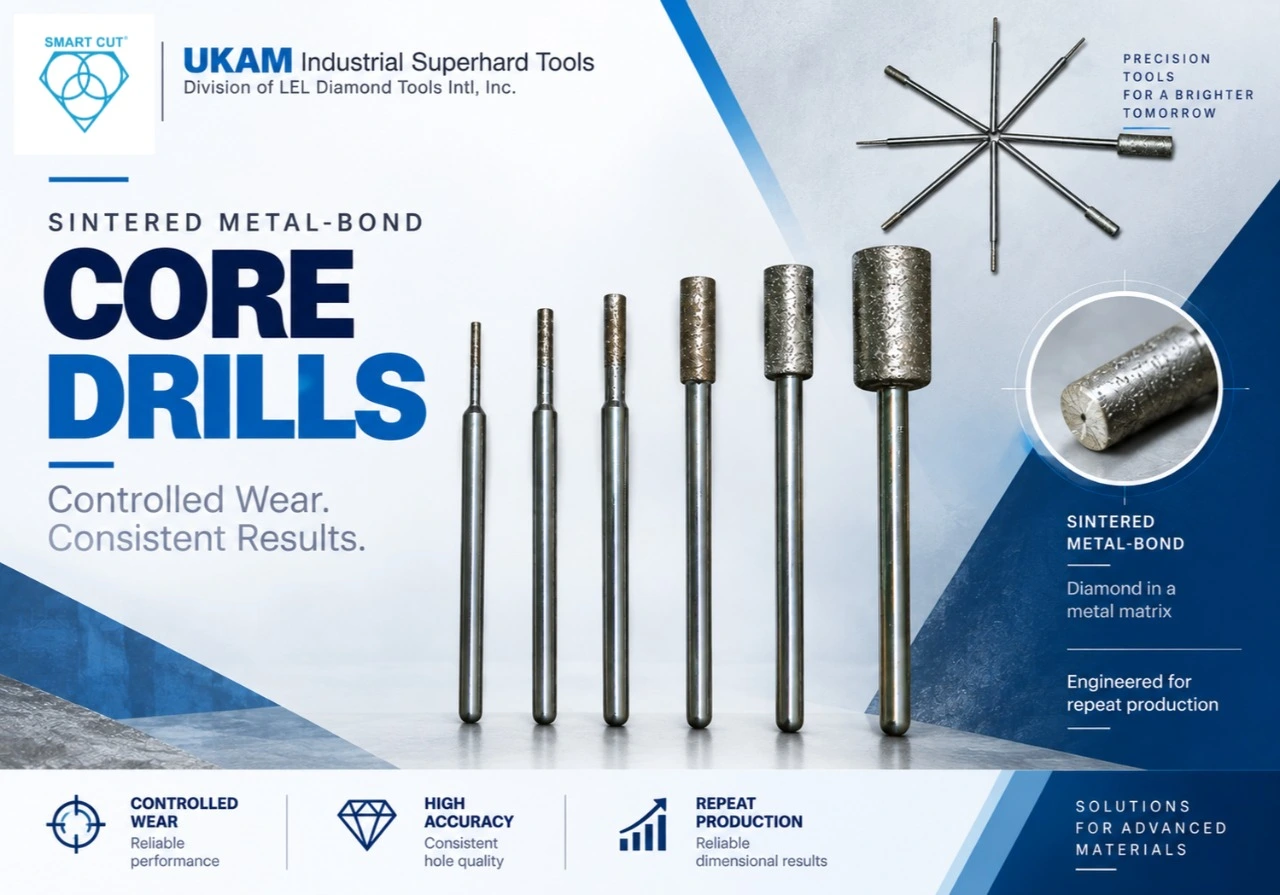
Sintered drills contain diamond within a metal matrix. As the working matrix wears, additional abrasive can become exposed. This construction can be useful for repeat production when controlled wear and consistent hole quality are important.
The matrix must wear at an appropriate rate. If it retains ineffective abrasive too long, the drill may rub, glaze, heat the workpiece, or lose penetration. If it wears too rapidly, useful diamond can be released prematurely and dimensional life may suffer.
Bond selection should account for both workpiece hardness and abrasiveness. Hardness alone does not describe how aggressively the material wears the matrix. Compare cutting behavior, abrasive condition, and wear observations before deciding that a harder or softer bond is needed.
Electroplated and brazed drills
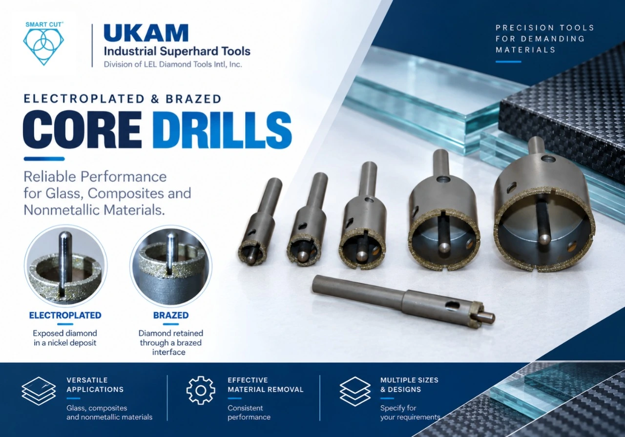
Electroplated drills retain exposed diamond in a nickel deposit. This construction can provide useful cutting action in glass, composites, and other applications when the geometry and abrasive specification are appropriate. Coverage and layer construction vary, so specify the actual design when comparing tools.
Brazed drills retain diamond through a brazed interface. They can be considered for selected composite and nonmetallic applications where exposed abrasive and material removal are priorities. Neither the plated nor brazed category alone establishes acceptable finish, tool life, or dry-drilling suitability.
Compare these constructions against your production requirement. A tool that performs well for a short development run may have different economics in continuous production. A longer-life construction must still meet the required edge quality and dimensional limits.
CVD diamond and PCD tooling
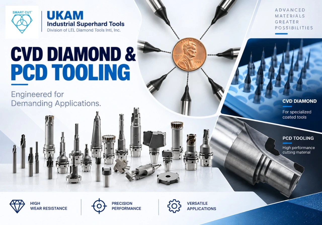
Chemical vapor deposition, or CVD, describes a method of producing diamond material or coatings. Polycrystalline diamond, or PCD, describes a diamond cutting material. These are related tooling options, but they are not simply alternative matrix hardnesses for a conventional abrasive core drill.
Their suitability depends on cutting geometry, substrate, material condition, and operating method. Evaluate them separately when the application calls for a defined cutting edge or specialized coated tool. Do not transfer recommendations between fired ceramics, green ceramics, composites, and nonferrous metals without reviewing the specific process.
Select diamond grit and concentration together
Diamond grit size influences how individual abrasive particles interact with the workpiece. Coarser diamond can support more aggressive removal and greater space around exposed particles in suitable constructions. It can also create larger damage features when the material or engagement is sensitive.
Finer diamond can support finer surface texture and more controlled edge formation. However, a fine specification can become ineffective if the abrasive exposure, bond, feed, or debris removal does not support cutting. Choosing the smallest available grit does not establish the best production result.
Start with the required edge and bore quality. Then evaluate cutting rate and wear. If the hole requires secondary grinding or polishing, include the material allowance and finishing cost. A slightly faster rough-drilling process may be useful when the next operation is already required.
State grit size with its designation system. A mesh number, a micron range, and a commercial grit code should not be treated as interchangeable labels. Confirm the actual specification when replacing or comparing a drill.
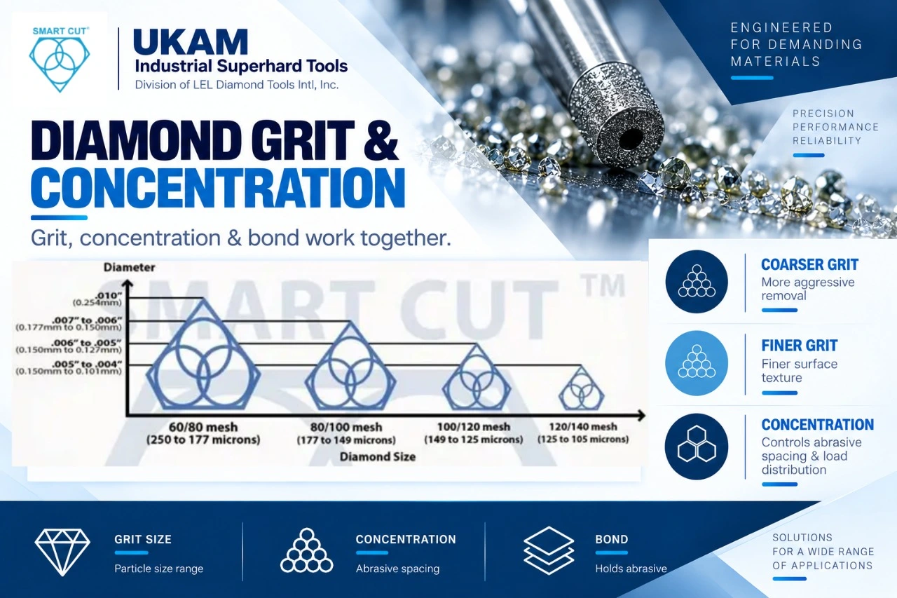
Diamond concentration describes abrasive content in the working layer. Under the conventional concentration scale, C100 corresponds to approximately 25 percent diamond by volume. It does not mean that the layer consists entirely of diamond. Confirm the notation used for the specific construction.
Concentration, grit, and bond jointly affect abrasive spacing, load distribution, chip clearance, and wear behavior. A higher concentration can change the number of active cutting points, but it does not guarantee faster drilling or longer useful life. Surface coverage on an electroplated tool also requires a different interpretation from abrasive volume in an impregnated matrix.
When comparing trials, record grit and concentration separately. Otherwise, a change in abrasive content can be mistaken for a bond or grit effect.
Select the rim, usable depth, and core-removal method
The rim controls initial engagement and the paths available for coolant and debris. Choose its design around workpiece condition, hole quality, and the required depth.
|
Rim configuration |
Reason to evaluate it |
Question to resolve |
|---|---|---|
|
Continuous |
Uninterrupted contact around the circumference can support controlled engagement. |
Can coolant and debris move adequately through the selected clearances? |
|
Slotted |
Openings can provide additional routes for coolant and debris. |
Will interrupted contact meet the edge-quality requirement? |
|
Segmented |
Separated abrasive sections can provide larger open spaces for removal and cooling. |
Does the workpiece tolerate the engagement pattern and loading? |
|
Serrated or special profile |
A designed contact pattern can address a particular entry or removal requirement. |
Has this geometry been qualified on the actual material and machine? |
These are selection considerations. Rim geometry, wall thickness, grit, and operating conditions can change the result within each category.
Usable depth and clearance
Usable drilling depth is the available working reach before the body, shoulder, mounting, or retained core limits travel. Overall tool length includes portions that may never enter the hole. Diamond section height describes the axial extent of the abrasive section and serves a different purpose.
Specify the required depth together with workpiece thickness and access conditions. Include fixture clearance and the space needed at breakthrough. A long tool is not automatically capable of producing a deep, accurate hole.
As depth increases, the process becomes more sensitive to alignment, unsupported length, slurry accumulation, and core friction. Specify how coolant reaches the working face and how debris leaves the hole. Long contact paths can make small clearance or alignment problems more significant.
For an illustrative 18 mm hole with 250 mm depth, the depth-to-diameter ratio is approximately 13.9. This indicates a substantial reach requirement. It does not establish that a particular standard drill can meet the requested tolerance.
Through-holes and blind holes
A through-hole requires an exit strategy. Plan workpiece support, remaining material thickness, and feed near breakthrough. Include a compatible backing arrangement when the application permits it.
A conventional hollow drill leaves an attached core in a blind hole. Plan core removal and bottom finishing as part of the process. Depending on the geometry, you may need a non-core-forming drill, a bottoming tool, or a separate finishing operation. Specify required bottom flatness, corner geometry, and remaining wall thickness before choosing the tooling.
Match the drill to the machine, coolant, and workholding
Machine capability sets practical limits on the tool specification. Confirm speed range, rigidity, mounting accuracy, available power, feed control, and coolant compatibility. These factors become especially important with small diameters, thin walls, deep holes, and brittle components.
Mounting and runout
Inspect the mounting surfaces, chuck or collet, adapters, and spindle condition. Confirm the exact shank or thread specification. Additional adapters and excessive projection can introduce alignment error or reduce stiffness.
Measure mounted runout at an appropriate smooth reference surface using a method suitable for the tool. A reading on a rough abrasive surface can reflect surface texture as well as eccentricity. Record the measurement location and total indicated runout so results can be compared meaningfully.
If holes are oversized, first verify the finished cutting diameter and mounting. Then check workpiece movement, vibration, and alignment. Tool replacement alone will not resolve an error introduced by the setup.
Speed and feed

Use operating recommendations for the specific tool and material as your starting point. Observe the ratings of the drill, mounting components, and machine. Diameter affects peripheral speed, so copying RPM from a different drill size can change the abrasive engagement substantially.
For a given peripheral speed, a smaller diameter requires higher RPM than a larger diameter. This relationship helps compare setups, but it does not identify the correct operating speed by itself.
Feed must maintain useful cutting without exceeding the tool or workpiece limits. Excessive loading can increase deflection and damage. Insufficient engagement can promote rubbing in some combinations. Record whether feed is controlled by displacement, force, or operator pressure because those methods respond differently as the tool wears.
Evaluate entry, steady drilling, and breakthrough separately. Change one major variable at a time during initial diagnosis. Once you understand individual effects, planned trials can evaluate interactions between speed, feed, coolant, and tool specification.
Coolant delivery and debris removal
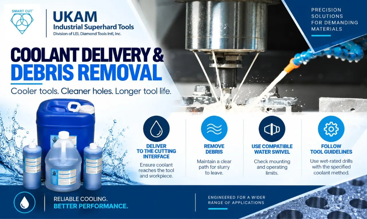
Coolant helps manage heat, friction, and debris. Effective delivery requires a path to the cutting interface and a route for slurry to leave. A high pump-flow reading does not prove that the working face receives adequate coolant.
Check passages, nozzles, filtration, concentration where applicable, and compatibility with the workpiece. Inspect whether flow changes as the drill enters the hole. Deep drilling may require a different delivery arrangement from shallow work.
A compatible water swivel can deliver fluid through the tool. Confirm its mounting, operating limits, sealing arrangement, and fluid compatibility as part of the setup. Through-tool delivery must still provide adequate drainage and debris clearance.
Use wet-rated drills with their specified coolant method. Consider dry drilling only when the tool and application permit it. Air delivery is not automatically an equivalent substitute for liquid cooling.
Workholding, support, and guidance
Support the workpiece close enough to the drilling area to control movement and flexing. Avoid clamping that distorts the part or introduces damaging stress. Thin or fragile components may require a dedicated support method.
A drilling template or guide can help locate the tool during entry when designed with appropriate clearance and alignment. It should not force a misaligned drill into position or rub against an unsuitable surface. Plan fixture drainage and core access along with positioning.
Diagnose hole defects and declining performance systematically
Record when the problem begins. Entry damage, breakthrough damage, and progressive deterioration suggest different checks. Inspect representative accepted and rejected holes using the same measurement method.
Entry and exit chipping
For entry chipping, check initial contact, alignment, mounted runout, guide clearance, and local support. Determine whether the defect appears immediately or develops after the drill begins tracking into the material.
For exit chipping, examine support beneath the exit surface and the feed condition as the remaining material becomes thin. Confirm that the backing method, if used, is compatible with the workpiece and tool. Compare exit damage separately from entry damage.
For chipping along the bore, investigate material variation, vibration, abrasive specification, tool condition, and coolant access. A smaller visible chip does not by itself establish acceptable subsurface integrity. Use the inspection method required by the component’s function.
Oversize, taper, and location error
Measure hole diameter at defined depths and orientations. An entry measurement alone can miss taper or a local defect. Check the mounting, alignment, workpiece motion, and dimensional condition of the tool before changing its nominal size.
If the error increases with depth, inspect the relationship between tool projection, guidance, side clearance, and debris accumulation. If it increases with tool use, examine wear, loading, and changes in drilling force.
Slow cutting, heat, and tool conditioning
When penetration falls, first confirm that material, feed, speed, and coolant conditions have not changed. Check for blocked passages, packed debris, a trapped core, and visible damage. These conditions require different responses from a glazed abrasive surface.
Some impregnated diamond tools can be dressed using an appropriate procedure to expose effective abrasive. Use the conditioning method recommended for the particular bond and geometry. Recheck dimensions and cutting performance afterward.
Do not automatically apply an aggressive sintered-tool dressing procedure to electroplated or brazed drills. Their working abrasive can be damaged or removed. Cleaning deposited material and removing bond material are different actions. Confirm which action is appropriate before conditioning the tool.
Truing addresses geometry or concentricity. Dressing addresses the working abrasive condition. Neither action restores a cracked body or corrects an unsuitable mounting arrangement. Remove visibly damaged tools from use and investigate the cause.
Compare trials using quality, output, and total cost
Define acceptance before testing. Record diameter limits, maximum permitted chip size, taper, surface requirements, and the inspection method. Use representative material and a documented setup.
Measure performance at planned intervals throughout tool use. A trial that checks only the first few holes can miss deterioration. Record conditioning, tool changes, and rejected parts as part of the result.
Yield and accepted output measure different things
The following hypothetical example illustrates the distinction. The figures are not UKAM test results or operating recommendations. Assume each trial drills 100 holes. Every hole receives the same inspection. Chip width means the greatest radial extent of visible edge breakout from the nominal hole boundary, measured by the same method. Table values show the largest recorded chip in each trial.
|
Measure |
Trial A |
Trial B |
Trial C |
|---|---|---|---|
|
Average drilling time per hole |
45 seconds |
35 seconds |
27 seconds |
|
Maximum entry chip width |
0.05 mm |
0.06 mm |
0.12 mm |
|
Maximum exit chip width |
0.08 mm |
0.10 mm |
0.25 mm |
|
Holes accepted without rework |
97 of 100 |
98 of 100 |
89 of 100 |
|
First-pass yield |
97% |
98% |
89% |
|
Calculated accepted holes per drilling hour |
77.6 |
100.8 |
118.7 |
First-pass yield equals holes accepted without rework divided by total holes drilled. Calculated accepted holes per drilling hour equals 3,600 divided by drilling seconds per hole, multiplied by first-pass yield as a decimal.
Trial B has the highest yield. Trial C has the highest calculated accepted output per drilling hour. The latter calculation excludes loading, inspection, rework, tool changes, and downtime. Actual production output must include the time that constrains your operation.
Suppose this illustrative process requires a minimum first-pass yield of 95 percent, with each accepted hole meeting entry and exit chip limits of 0.10 mm and 0.15 mm respectively, plus its dimensional requirements. Trial C fails the yield threshold. Its maximum chip values also show that some holes exceed the edge limits. Trial B would be the faster of the two trials meeting the stated yield threshold.
If the yield threshold or cost structure changes, the preferred choice may also change. The one-percentage-point difference between A and B represents one hole in these small trials. Repeat testing is needed before treating that difference as a reliable production advantage.
Calculate cost per final accepted hole
Tooling cost per hole measures only the allocated drill expense. Total process cost can include machine time, labor, setup, inspection, coolant, conditioning, tool changes, rework, and scrapped material. Count each cost once and use a consistent boundary.
Cost per final accepted hole equals total process cost for the evaluated production divided by final accepted holes, including successful rework once.
The following separate hypothetical example compares equal starting quantities. Currency values are illustrative. The process-cost line includes drilling, handling, setup, coolant, and inspection. Rework is additional. Scrap loss covers the material value lost in rejected parts, which is excluded from the other lines. Common starting-material costs are omitted from both alternatives.
|
Measure |
Drill A |
Drill B |
|---|---|---|
|
Total holes attempted |
1,000 |
1,000 |
|
Holes accepted without rework |
980 |
920 |
|
Additional holes accepted after rework |
10 |
60 |
|
Final accepted holes |
990 |
980 |
|
Scrapped holes |
10 |
20 |
|
Allocated tooling cost |
$300 |
$220 |
|
Process cost |
$900 |
$760 |
|
Rework cost |
$40 |
$240 |
|
Scrap material loss |
$100 |
$200 |
|
Total compared cost |
$1,340 |
$1,420 |
|
Cost per final accepted hole |
$1.35 |
$1.45 |
Drill A has the higher tooling expense but the lower compared cost per final accepted hole under these assumptions. Different scrap values, rework costs, or process times could change the result. Use your own measured costs and ensure that the compared tools perform equivalent work.
Define useful tool life by an agreed endpoint. That endpoint may be a hole-quality limit, maximum drilling time, minimum usable abrasive section, or another approved condition. Keep quality-limited retirement separate from physical breakage when analyzing failures.
Decide when a custom drill is justified
Custom tooling is useful when an available specification cannot satisfy the required combination of geometry, quality, access, and production performance. Examples include unusual cutting OD or ID, restricted wall thickness, special reach, nonstandard mounting, or a rim designed for a particular material.
First determine whether the limitation comes from the tool or the process. A custom diameter will not correct unstable workholding. A longer drill will not solve inadequate coolant access unless the design and setup address that requirement together.
Provide a drawing that distinguishes finished hole requirements from tool dimensions. Include relevant fixture clearances and the condition of the material. If you have a current tool, share its measured performance and failure mode. Photographs and sample inspection results can make the initial review more productive.
We manufacture custom diamond drills to application requirements and drawings. Confirm dimensional capability, quantity, and lead time for the complete specification when requesting a quotation.
Frequently Asked Questions
Start with material and condition, required hole diameter, depth, quality limits, machine, and quantity. See our guide on how to order for the full submission checklist. Identify through or blind drilling and whether the core must be recovered. Add the current tool specification and performance if you are replacing an existing drill.
No. A thinner cutting wall can reduce material removal, but the supporting structure and setup must remain stable. Compare edge quality, dimensional consistency, wear, and total cost at the required depth, or request a quote to compare specific options.
Some specifications work across multiple materials. Qualification on one material does not establish performance on another. Differences in hardness, abrasiveness, structure, and thermal sensitivity can require a change in bond, grit, geometry, or operating method.
Nominal size may differ from the measured cutting envelope. Mounted runout, abrasive protrusion, deflection, and workpiece movement can also affect the result. Measure the tool and setup before changing the ordered diameter.
No. Conditioning depends on construction. Some impregnated tools can be dressed with an appropriate procedure. Electroplated and brazed tools require construction-specific guidance. Inspect for loading or damage before assuming that bond removal is needed.
There is no useful universal hole count. Material, depth, tool design, operating conditions, and acceptance limits all affect life. Compare accepted holes produced before the agreed retirement point under documented conditions. Our full FAQ page covers additional tool-life questions.
A conventional hollow drill leaves a core. A flat-bottom blind hole requires a planned core-removal and finishing method or a suitable non-core-forming or bottoming tool. Define bottom geometry and tolerance before selecting the process.
Get an application-specific diamond core drill recommendation
Send us your material, required hole diameter and depth, quality requirements, machine type, and quantity. Tell us whether you need a through-hole, blind hole, or recovered core.
If you are solving an existing problem, include the current tool specification, drilling conditions, and a short description of the defect. A drawing or clear photograph of the hole and setup can help us identify what additional information is needed.
At UKAM Industrial Superhard Tools, we can review standard and custom diamond core drill options around your application. Our objective is to help you select a specification that supports the required hole quality, useful tool life, production output, and cost.
Explore diamond core drills and request selection assistance
Trusted by Tens of Thousands of Manufacturers, Laboratories,
Research Institutions Worldwide Since 1990
American Based Manufacturer
Established in 1990
