








































Diamond Micro Drills for Accurate Holes and Longer Tool Life


Table of Contents
Toggle
American Based Manufacturer

Established in 1990


Custom manufacturing


How to select tool construction and qualify the complete drilling process
Selecting a diamond micro drill starts with the hole you must produce. Define the material, diameter limits, depth, position, edge condition and production requirement. Then match the tool construction and geometry to the capability of your machine and inspection process.
A drill can have the correct nominal diameter and still produce taper, misplaced holes, entry chipping, exit breakout or early tool failure. At small diameters, mounted runout, unsupported tool length, feed control and debris removal can determine whether the tool performs consistently.
The goal is repeatable production of accepted holes at an acceptable total cost. Useful tool life ends when the process can no longer meet the agreed quality requirements, even if the drill remains capable of removing material.
Micron level hole accuracy is a requirement to verify on the finished workpiece. It is not a result guaranteed by choosing a small drill or specifying a tight tool diameter tolerance.
Define the hole before you choose the drill
Start with the drawing and the actual workpiece. Record the exact material grade, thickness and condition. Identify whether you are drilling a through hole, a blind hole or a feature that intersects another cavity. Coatings, curved entry surfaces and layered materials can change tool engagement and support.
Specify diameter limits separately from position, roundness and taper. A hole that passes an entrance diameter check may still fail at depth or be in the wrong location. Define entry and exit damage independently from hole diameter.
|
Requirement |
What to document |
|---|---|
|
Material |
Grade, binder or reinforcement where relevant, thickness, coatings and material condition. |
|
Hole geometry |
Nominal diameter, upper and lower limits, depth, depth to diameter ratio and through or blind configuration. |
|
Location and form |
Position relative to drawing datums, roundness, taper and any straightness requirement. |
|
Surface integrity |
Permitted entry and exit damage, bore finish and any subsurface damage requirement. |
|
Machine and mounting |
Spindle capability, holder, shank size, mounted runout, tool projection, feed control and workholding. |
|
Production and inspection |
Accepted output required, cycle time, current failure mode, inspection method and stopping criteria. |
For example, a 0.300 mm hole with a diameter tolerance of ±0.005 mm has an allowed range of 0.295 to 0.305 mm. That establishes the size requirement. It does not automatically permit 0.005 mm of runout or establish an acceptable edge chip size.
Depth also needs context. A 1.5 mm deep hole made with a 0.30 mm drill has a depth to diameter ratio of 5. This ratio helps describe the application, but does not establish that a particular drill geometry can reach the bottom or clear debris effectively.
Choose the construction for the material removal task
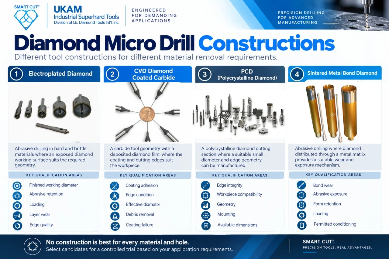
Diamond micro drills include several tool constructions. Some remove material through exposed abrasive particles. Others use defined cutting edges supported by a diamond coating or a polycrystalline diamond cutting section. These tools do not share identical geometry, wear behavior or conditioning requirements.
|
Construction |
When to investigate it |
What to qualify |
|---|---|---|
|
Electroplated diamond |
Abrasive drilling in hard and brittle materials where an exposed diamond working surface suits the required geometry. |
Finished working diameter, abrasive retention, loading, layer wear and edge quality. |
|
CVD diamond coated carbide |
A carbide tool geometry with a deposited diamond film, where the coating and cutting edges suit the workpiece. |
Coating adhesion, edge condition, effective diameter, debris removal and coating failure. |
|
PCD |
A polycrystalline diamond cutting section where a suitable small diameter and edge geometry can be manufactured. |
Edge integrity, workpiece compatibility, geometry, mounting and available dimensions. |
|
Sintered metal bond diamond |
Abrasive drilling where diamond distributed through a metal matrix provides a suitable wear and exposure mechanism. |
Bond wear, abrasive exposure, form retention, loading and permitted conditioning. |
No construction is best for every material and hole. A longer lasting working layer offers little benefit if it requires excessive force, loses the required geometry or produces unacceptable edge damage. Use the comparison to select candidates for a controlled trial.
CVD describes a deposition process. In this article, CVD diamond coated carbide means a carbide substrate carrying a diamond film. It should not be confused with a freestanding CVD diamond cutting element or a non-diamond coating deposited by CVD.
Coating failure deserves separate attention. Published ceramic-drilling research reports diamond coating flaking and shows that feed rate and coating thickness can affect its development. Inspect the actual failure mechanism before assuming that a different coating thickness will improve life. See the ceramic-drilling research in the technical references.
Match abrasive size to the construction
For tools using discrete abrasive particles, finer diamond may help limit localized brittle fracture and improve finish. It can also change cutting forces, loading and material removal. Coarser diamond may improve removal under suitable conditions while increasing the severity of individual contacts.
Specify particle size together with bond, working diameter and geometry. Do not transfer a loose-abrasive grit recommendation directly to a PCD cutting edge or a CVD film. For these constructions, grain structure, coating condition and edge geometry also need consideration.
Confirm whether diamond is appropriate
Material hardness alone does not establish tool suitability. Confirm the material chemistry, structure and machining conditions. Depending on the application, another cutting material or a different hole-making process may provide better results. Include this check before committing to a diamond construction.
Control geometry and unsupported tool length
Specify working diameter, working length, shank size, transition geometry and tip configuration. Confirm that the tool can reach the full depth while maintaining clearance between the workpiece and any larger shank or shoulder.
Keep tool projection as short as the application permits. Projection is the exposed distance from the holder face to the tool tip. Working length is the active section intended to remove material. These dimensions are related, but they are not interchangeable.
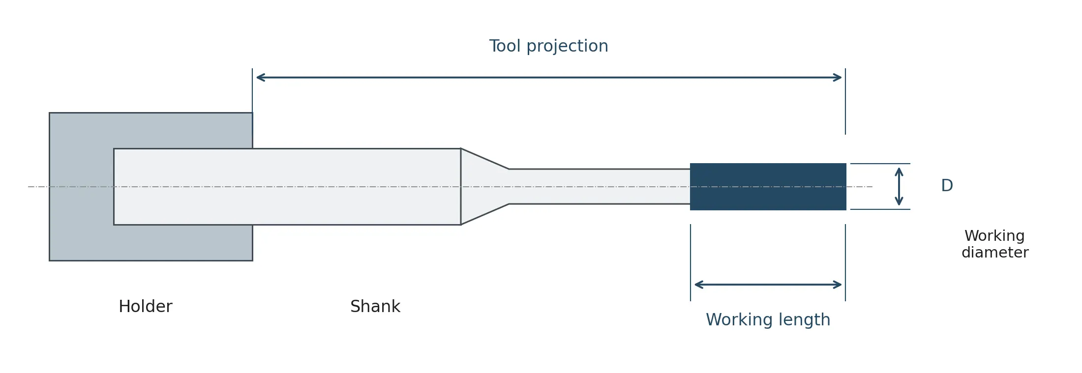
Figure 1. Generic abrasive micro drill geometry. The illustration is schematic and not to scale. Actual tip shape, transitions and dimensions depend on the construction.
A long reduced section can bend even when the shank is held securely. Extra working length does not automatically provide useful drilling depth. It also increases the need to confirm stiffness, clearance and removal of debris.
Choose solid drilling or core drilling deliberately
A solid drilling tool removes material across the hole cross section. A core drill removes an annular path and leaves a core that must be managed. Core drilling may reduce the volume removed where a suitable outside diameter, inside diameter and wall thickness can be produced.
At very small diameters, the available annular wall and core removal method can limit feasibility. For blind features, confirm how the retained material will be released and removed. Do not select a core drill solely because the workpiece is brittle.
Measure runout against the available tolerance
Inspect the assembled tool system. A holder specification describes only part of that system. Contamination, shank condition, clamping, tool form and projection can change the condition at the working section.
State exactly how runout is measured. Total indicated runout, or TIR, is the difference between the maximum and minimum indicator readings over one revolution under the defined inspection setup. Radial eccentricity is the offset between the tool center and the rotation axis.
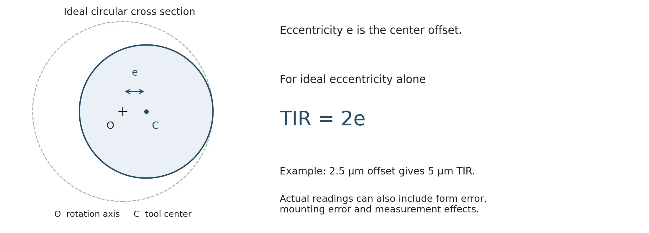
Figure 2. Eccentricity and TIR are different quantities. The relationship TIR = 2e applies to an ideal circular section with pure eccentricity. The dashed circle indicates the outer swept boundary. Offsets are exaggerated.
Record the measurement location, projection, method and instrument capability. A reading on the shank does not establish runout at the cutting section. On a delicate micro tool, use a method that will not bend or damage the feature being measured.
A slow rotational check also does not establish behavior at operating speed. If performance changes with RPM, investigate the dynamic condition using an appropriate method and the machine builder’s guidance.
For a 0.20 mm drill, 5 μm represents 2.5% of nominal diameter. That illustrates scale, but it is not a prediction of hole oversize. Compare measured runout with the hole tolerance and the other sources of process variation. Do not assign the entire tolerance to runout.
Set speed feed and debris removal as a process
Use actual tool diameter when comparing rotational conditions. The peripheral surface speed is:
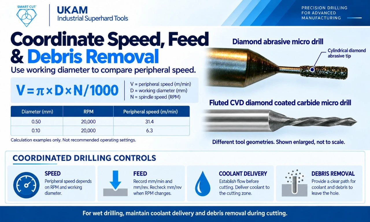
V = π D N / 1000
V is peripheral surface speed in m/min, D is working diameter in mm, and N is spindle speed in revolutions per minute. The expression describes the outer diameter. Local speed decreases toward the center of a solid tool.
|
Diameter |
RPM |
Peripheral surface speed |
|---|---|---|
|
0.50 mm |
20,000 |
31.4 m/min |
|
0.10 mm |
20,000 |
6.3 m/min |
These are calculations, not recommended operating speeds. The same RPM produces different peripheral speeds at different diameters. Obtain a starting condition for the actual construction, material and machine, then qualify it through measured trials.
Distinguish feed per minute from feed per revolution

Feed per revolution = feed per minute / RPM
At 20,000 RPM, an axial feed of 20 mm/min corresponds to 0.001 mm/rev, or 1 μm/rev. This is a unit example only. It is not a recommended feed and does not directly describe the load on each abrasive grain.
If RPM changes while feed per minute stays constant, feed per revolution changes. Record both values when comparing trials. Very low feed is not automatically better. Rubbing, dwell, loading or poor engagement can still damage the tool or workpiece.
Plan entry breakthrough and flushing
Support the workpiece close to the hole without obstructing the tool or coolant path. Identify curved or angled entry surfaces that may create uneven contact. Where required, qualify controlled entry and breakthrough feeds separately from the main drilling feed.
Coolant must reach the active contact and carry debris away. Record fluid type, concentration where applicable, filtration and delivery. Visible coolant around the workpiece does not prove that the bottom of the hole receives effective flushing.
Blind holes require particular attention because debris cannot leave through the exit. Where the tool and machine permit it, a qualified retract or peck sequence may improve removal. Do not assign a universal peck depth from diameter alone. Confirm that re-entry does not introduce side loading or damage.
When a backing material is used to support breakthrough, qualify its compatibility, contact with the workpiece and effect on debris removal. Avoid allowing a poorly supported thin section to move as the tool approaches the exit.
Verify hole quality with a capable measurement method
Define inspection before the trial. The measurement method must resolve the required feature with suitable uncertainty and repeatability. Display resolution alone does not establish measurement accuracy. Calibration, edge detection, focus, setup and operator technique can all affect the result.
NIST’s dimensional measurement guidance explains why results need an uncertainty assessment. For production decisions near a tolerance limit, agree on a decision rule that accounts for measurement uncertainty. Do not treat a marginal displayed value as certain acceptance.
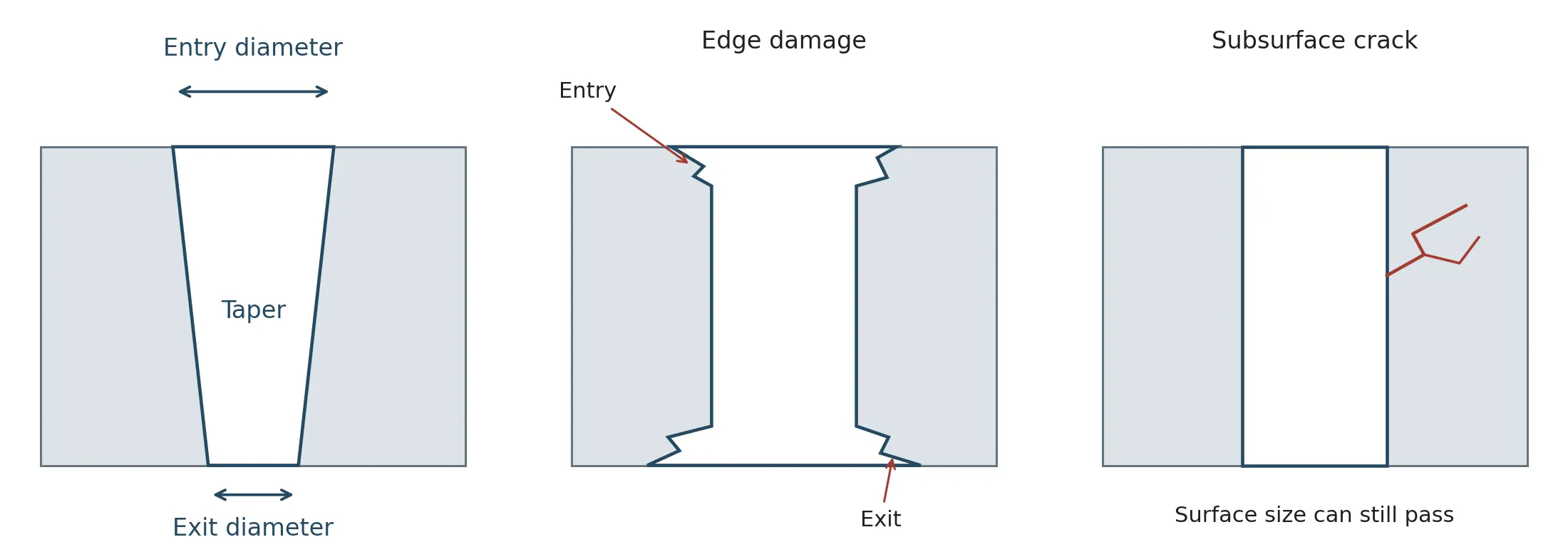
Figure 3. Schematic through-hole sections showing taper, edge damage and a subsurface crack. Defects are exaggerated. Surface diameter inspection alone does not establish internal form or subsurface integrity.
|
Quality characteristic |
What the inspection must establish |
|---|---|
|
Diameter and taper |
Measure at defined axial locations with a method suitable for the bore. Entrance and exit measurements alone do not establish the complete internal profile. |
|
Position and roundness |
Measure position relative to the required datums. Evaluate form independently from a single diameter measurement. |
|
Entry and exit damage |
Define the permitted damage and how it is measured. For example, distinguish radial breakout beyond the intended edge from the total damaged opening width. |
|
Surface finish |
Specify the required parameter, evaluation region and feasible bore measurement method. |
|
Subsurface integrity |
Use an application-appropriate method when required. Qualification may include sectioned samples or another validated technique. |
Clean and prepare samples consistently. Define lighting, focus and edge-detection settings for optical inspection. A chipped edge can change the apparent boundary, so specify whether size is measured on the intact bore or the damaged opening.
Check repeatability by measuring representative holes more than once. Include different operators when operator judgment affects acceptance. Where possible, compare the production method with an independent reference method.
Inspect first holes, intermediate intervals and holes approaching the rejection threshold. Choose the interval from observed drift and the consequence of missing a change. A final inspection of a worn tool cannot establish when its holes first became unacceptable.
Adjust the investigation to the workpiece
Material names identify a starting point. They do not establish one inevitable failure mode. Use the actual grade, structure and observed defects to select the next check.
Glass fused silica and sapphire
Investigate entry and exit damage, bore condition and any required subsurface integrity. Confirm support and breakthrough behavior. For crystalline workpieces, record orientation where it is relevant. Separate a good diameter result from evidence of acceptable edge and internal quality. See related guidance for glass and quartz applications.
Alumina silicon carbide and silicon nitride
Record grade, density, grain structure and material condition where available. Inspect for grain pullout, chipping, cracking, tool damage and dimensional drift. Compare engagement, runout, debris removal and abrasive condition before assigning a defect solely to heat or grit size. See related guidance for ceramic and porcelain applications.
Cemented carbide and composites
For cemented carbide, identify binder content and grade. For composites, document reinforcement, orientation and layer interfaces. Inspect progressive tool condition and changes in hole form. Different constituents can affect both tool wear and local damage.
Semiconductor and diamond based workpieces
Use the actual substrate and surface requirements to define the process for semiconductor materials. Small edge defects may be unacceptable even when diameter passes. If the workpiece itself is PCD, identify it as polycrystalline diamond workpiece material so it is not confused with PCD tool construction.
Qualify changes through repeated trials
Establish acceptance and a baseline
Define the acceptance criteria, measurement method and tool stopping conditions first. Run the existing process using representative material. Record tool identity, setup, actual parameters, accepted and rejected holes, cycle time and the observed limiting mechanism.
Use screening trials to identify useful changes
During initial troubleshooting, change one major variable where practical. This helps identify likely causes. Keep the remaining conditions controlled and document unavoidable changes. When factors interact, a planned experiment may be more informative than continuing indefinitely with isolated adjustments.
Repeat across tools and relevant conditions
A long run on one drill does not establish consistency between drills. Repeat promising conditions using independent tools and, where relevant, representative material lots or setup repeats. Select the number of tools and holes from the variation observed, required confidence and cost of a wrong decision. There is no universal qualifying hole count.
Separate a screening result from a tool life result
The following hypothetical example illustrates how to report screening data. It is not UKAM production data or a comparison of named tool technologies. The hole diameter requirement is 0.300 mm ±0.005 mm. Each candidate uses three independent tools, with 200 attempted holes per tool. Every hole receives the agreed diameter and edge inspection.
|
Screening result |
Candidate A |
Candidate B |
|---|---|---|
|
Tools tested |
3 |
3 |
|
Total attempted holes |
600 |
600 |
|
Average measured diameter |
0.303 mm |
0.301 mm |
|
Measured diameter range |
0.299 to 0.307 mm |
0.298 to 0.306 mm |
|
Diameter rejects |
30 |
6 |
|
Additional edge-only rejects |
12 |
6 |
|
Accepted holes |
558 |
588 |
|
Acceptance rate |
93% |
98% |
|
Average cycle per attempted hole |
11 seconds |
14 seconds |
The rejection categories do not overlap. All other specified criteria pass in this example. Accepted holes equal attempted holes minus diameter rejects minus additional edge-only rejects. Thus, Candidate A produces 600 − 30 − 12 = 558 accepted holes.
Candidate B has higher observed acceptance during this screening run. Candidate A has the shorter cycle. Neither average diameter proves that every hole passes. Preserve the individual measurements, results by tool and order of production to evaluate spread and drift.
The trial stops after 200 holes per tool. It therefore does not establish full useful tool life. Continue selected tools to a defined quality or wear limit before making a tool life claim. If a test ends before the limit, report the demonstrated output and state that the limit was not reached.
Compare cost per accepted hole
Calculate economics using the accepted output and a clearly defined cost boundary. Include tool purchase, machining, tool changes, approved conditioning, inspection, rework and the value of scrapped workpieces where applicable. Avoid counting an expense twice if it is already included in the machine rate.
Cost per accepted hole = total included cost / accepted holes
The following separate hypothetical example uses Tool X and Tool Y. These costs are unrelated to the preceding screening trial. The machine rate is $100/hour. Each stated cycle applies to every attempted hole, including rejects. Conditioning occurs at the listed intervals, with no conditioning after the final hole.
|
Cost input or result |
Tool X |
Tool Y |
|---|---|---|
|
Tool purchase price |
$85.00 |
$55.00 |
|
Attempted holes per tool |
1,200 |
650 |
|
Acceptance rate |
99% |
96.5% |
|
Expected accepted holes |
1,188 |
627.25 |
|
Cycle per attempted hole |
18 seconds |
14 seconds |
|
Conditioning interval |
300 holes |
150 holes |
|
Conditioning events during life |
3 |
4 |
|
Cost per conditioning event |
$8.00 |
$6.00 |
|
Total conditioning cost |
$24.00 |
$24.00 |
|
Total machining cost |
$600.00 |
$252.78 |
|
Total included cost |
$709.00 |
$331.78 |
|
Cost per accepted hole |
$0.597 |
$0.529 |
For Tool X, machining cost is 1,200 × 18 ÷ 3,600 × $100 = $600. Adding the $85 tool and $24 conditioning cost gives $709. Dividing by 1,188 accepted holes gives approximately $0.597 per accepted hole.
For Tool Y, the same method gives approximately $0.529. Tool Y has the lower calculated cost under these assumptions, despite its shorter life and lower acceptance rate. The faster cycle outweighs those disadvantages within this limited cost boundary.
The fractional accepted count is an expected value from the assumed acceptance rate. Actual production counts are whole numbers. Keep full precision during the calculation and round the final displayed costs.
This example treats each conditioning charge as the complete cost of that event. It excludes additional tool change time, inspection, rework and workpiece scrap value. Add those items before making the production decision. Expensive rejected parts or substantial replacement downtime can change the ranking.
Use conditioning costs only when the operation is permitted for the construction. Cleaning removes deposits. Dressing changes the working surface or abrasive exposure. Reconditioning may involve restoring or replacing a cutting section. Obtain a construction-specific procedure before including any of these operations in a life estimate.
Use defects to guide the next verification
The timing and location of a defect help prioritize checks. They do not prove the cause. A setup problem can worsen during a run, while a damaged or unsuitable tool can fail immediately.
|
Observed problem |
Possible contributors |
First verification |
|---|---|---|
|
Oversize from the first holes |
Effective tool diameter, mounted runout, entry deflection or measurement method. |
Confirm the inspection method, working diameter and mounted condition. |
|
Hole size drifts during the run |
Wear, loading, coating loss, thermal change or unstable cutting. |
Compare measurements in production order with tool condition and actual settings. |
|
Taper or depth-related error |
Deflection, inadequate clearance, loading or poor flushing. |
Measure at defined depths and check projection, geometry and debris removal. |
|
Entry chipping |
Uneven engagement, unsupported surface, runout or abrasive condition. |
Inspect the entry surface, support and initial feed behavior. |
|
Exit breakout |
Breakthrough force, thin-section movement or inadequate support. |
Check exit support and the actual breakthrough sequence. |
|
Repeated breakage |
Bending, mounting stress, collision, loading or excessive force. |
Locate the break and inspect clamping, clearance, projection and the full cycle. |
|
Increasing cycle time or load |
Loading, worn cutting structure, restricted flushing or process drift. |
Inspect the working surface and verify actual coolant and feed conditions. |
|
Position variation |
Datum or fixture error, machine positioning, entry wander or measurement setup. |
Verify datums, workholding, positioning and engagement at the surface. |
For a progressive diameter change, do not assume that wear must make the hole larger. The result depends on how wear changes the cutting envelope, forces and stability. Confirm the direction of tool and hole change with measurements.
Prepare a complete application request
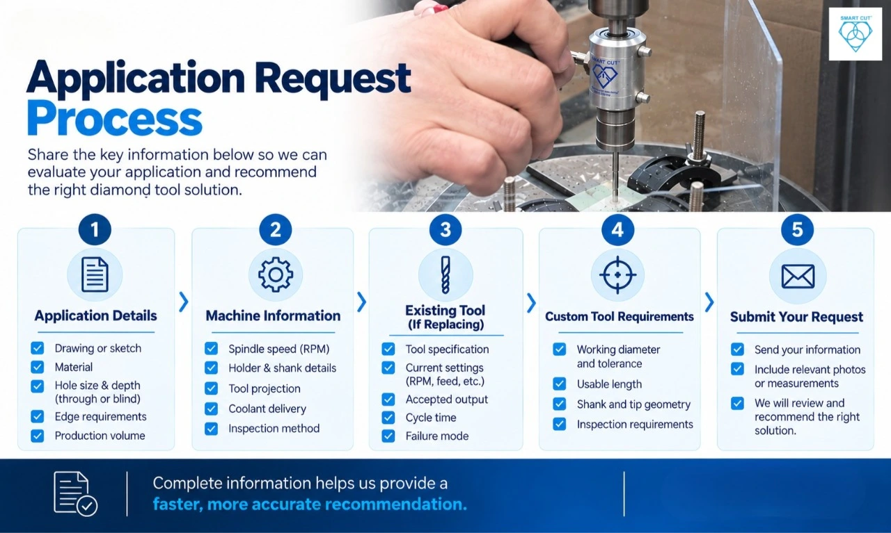
UKAM Industrial Superhard Tools manufactures standard and custom diamond micro drills and related precision tooling. We evaluate the material, hole requirement, tool geometry and machine conditions together when reviewing an application.
Provide your drawing or a dimensioned sketch, exact material, diameter limits, depth, through or blind configuration, edge requirements and production volume. Include spindle speed capability, holder and shank details, current tool projection, coolant delivery and available inspection methods.
If you are replacing an existing tool, include its specification, current settings, accepted output, cycle time and the observed failure mode. Representative measurements and clear photographs of the tool and hole defects make the problem easier to assess.
For custom tooling, confirm the working diameter and tolerance, usable length, shank, tip geometry and inspection requirements for the proposed construction. Availability of a small diameter does not establish a finished-hole tolerance or performance guarantee.
Frequently asked questions
Tool diameter control supports the process, but finished-hole accuracy depends on the mounted tool, machine, workholding, cutting conditions and measurement method. Qualify the required tolerance on representative parts.
There is no single RPM for all micro drills. Use the actual working diameter, tool construction, material and machine limits to establish a starting condition. Record feed per revolution as well as feed per minute, then qualify hole quality and tool condition.
First identify the failure mechanism. Lower feed will not correct poor clamping, runout, inadequate clearance, side loading or trapped debris. Inspect the complete cycle and change the condition supported by the evidence.
Define it by a specified quality or wear limit and report accepted holes up to that limit. Also record attempted holes, rejects and any approved conditioning. If the test ends before the limit, report demonstrated life rather than an estimated maximum.
Trusted by Tens of Thousands of Manufacturers, Laboratories,
Research Institutions Worldwide Since 1990
American Based Manufacturer
Established in 1990
