








































How to Select Diamond Tools for Composites: Cutting, Drilling, and Grinding Considerations


Table of Contents
Toggle
American Based Manufacturer

Established in 1990


Custom manufacturing


Composite machining rarely fails because the abrasive is simply “not hard enough.” The more common problem is a mismatch between the composite structure, tool construction, machine conditions, and the quality requirement.
A CFRP component may suffer delamination while a GFRP part shows fiber pullout. Aramid can produce fuzzing, honeycomb can collapse at the cell wall, and ceramic matrix composites can develop matrix cracking or fiber damage. The same diamond tool specification for composites should not be expected to solve all of these problems.
For engineers selecting diamond tools for composites, the starting point should be the material, machining operation, finished geometry, machine, and production requirement. Diamond grit, concentration, bond, tool geometry, and cutting configuration then follow from those conditions. UKAM’s technical knowledge center similarly emphasizes the relationship between material, geometry, machine capability, and production requirements when selecting diamond tooling.
Why Engineers Reconsider Diamond Tooling
A tooling change usually begins with a production problem rather than a product search.
|
Production symptom |
What to investigate first |
|---|---|
|
CFRP edge delamination |
Feed, support, tool edge condition, abrasive specification |
|
Fiber pullout |
Cutting action, grit, bond, tool condition |
|
Aramid fuzzing |
Edge geometry, abrasive exposure, cutting direction |
|
Honeycomb cell collapse |
Cutting force, support, tool geometry |
|
CMC matrix cracking |
Cutting force, thermal condition, grit and bond |
|
Rapid tool wear |
Reinforcement content, bond wear, abrasive exposure |
|
Excessive heat |
Cutting load, coolant, tool condition, process parameters |
|
Dimensional drift |
Tool wear, runout, deflection, mounting |
The first question should therefore be: What failure mode are we trying to eliminate? The second is: Which tool and process variables directly influence that failure mode?
This prevents a common mistake: changing the diamond grit when the actual problem is workholding, runout, coolant delivery, or excessive feed.
Establish the Baseline Before Changing the Tool
A tool trial is difficult to evaluate if the original process was never documented. Record the conditions that define the current result.
|
Parameter |
Record before trial |
|---|---|
|
Composite |
Material, grade, fiber type, matrix |
|
Reinforcement |
Carbon, glass, aramid, ceramic or metal |
|
Fiber content |
Percentage or manufacturer specification |
|
Workpiece |
Thickness, laminate structure, coating |
|
Operation |
Cutting, drilling, grinding |
|
Tool |
Diameter, width, grit, concentration, bond |
|
Machine |
Spindle speed, power, rigidity |
|
Runout |
Measured radial runout where possible |
|
Coolant |
Type, flow and delivery method (see coolant delivery accessories) |
|
Feed |
Feed rate and engagement — see RPM & feed rate calculation guide |
|
Quality |
Dimensions, edge condition, surface finish |
|
Production |
Cycle time, tool life, scrap and rework |
The finished requirement should be documented before tooling is selected. For drilling, this includes diameter, depth, tolerance, roundness, taper, surface finish, and entry and exit conditions.
Engineering principle
Select the Tool Around the Machining Operation
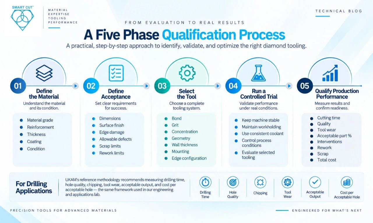
The same composite may require different diamond constructions for cutting, drilling, and grinding.
|
Operation |
Primary requirement |
Tool variables to evaluate |
|---|---|---|
|
Cutting |
Low damage and controlled kerf |
Blade construction, grit, bond, rim, thickness |
|
Drilling |
Hole quality and stable penetration |
Core diameter, wall thickness, grit, bond, rim — see selecting diamond drills for composites |
|
Grinding |
Surface removal and dimensional control |
Wheel bond, grit, concentration, wheel geometry |
For drilling, the cutting outside diameter influences the produced hole while the inside diameter influences the recovered core. Radial cutting wall thickness can be calculated as:
Radial wall thickness = (OD − ID) ÷ 2
For example, a 20 mm OD and 16 mm ID gives a 2 mm radial cutting wall. The calculation defines the tool geometry, not a guaranteed finished hole size — a point covered in more depth in UKAM’s complete guide to diamond core drills. Actual results are also influenced by abrasive protrusion, wear, runout, deflection, and material removal behavior.
Match Tool Construction to the Composite
The diamond itself is only part of the complete cutting system. The bond controls how the abrasive is retained and exposed during operation.
|
Construction |
General cutting behavior |
Composite applications to investigate |
|---|---|---|
|
Progressive abrasive exposure as matrix wears |
Repetitive drilling and difficult abrasive materials |
|
|
High exposed abrasive and open cutting action |
Selected composites and specialized geometries |
|
|
Brazed diamond |
Strong abrasive retention with exposed cutting points |
Fast stock removal and selected composite applications |
|
Resin bond |
Controlled abrasive action and finishing capability |
Applications requiring surface control |
|
Defined diamond cutting surface |
Specialized precision applications |
|
|
PCD |
Defined polycrystalline diamond cutting edge |
Composite machining where edge geometry and wear resistance are priorities |
UKAM describes sintered tooling as containing diamond within a metal matrix, with additional abrasive becoming exposed as the matrix wears — see the sintered metal bond core drill example. UKAM’s material also identifies electroplated and brazed constructions for selected glass, composite, and nonmetallic applications, as outlined on the electroplated diamond product page.
A critical selection point: A harder bond is not automatically better. If the matrix holds worn diamond for too long, the tool can rub, glaze, generate heat, and lose cutting efficiency. If the matrix wears too quickly, useful abrasive can be released before the tool reaches its expected dimensional life.
The correct question is: How should the abrasive wear relative to this particular composite? UKAM’s guide on diamond tool bond types and when to use them walks through this decision in more detail.
Diamond Grit and Concentration Must Be Selected Together
Grit affects how individual diamond particles interact with the workpiece.
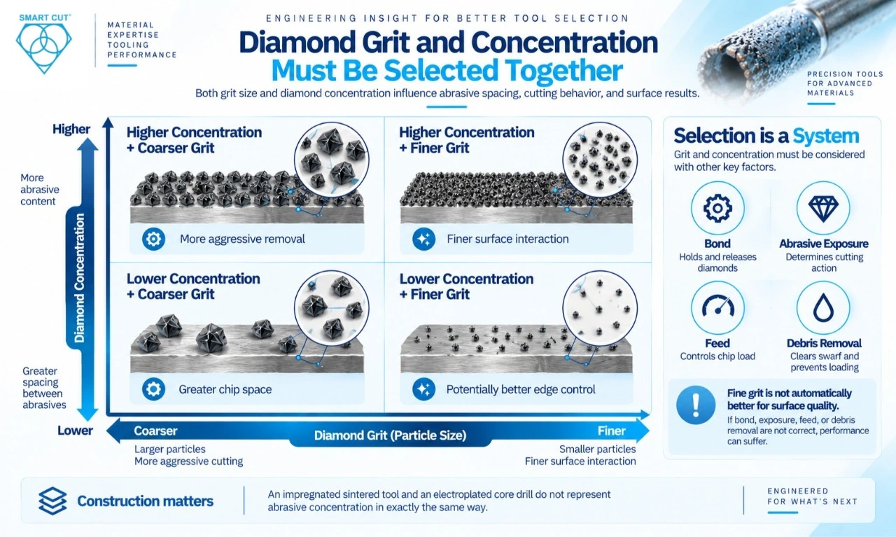
|
Selection tendency |
Possible result |
|---|---|
|
Coarser grit |
More aggressive removal and greater chip space |
|
Finer grit |
Finer surface interaction and potentially better edge control |
|
Higher concentration |
More abrasive content and different load distribution — see what diamond concentration means |
|
Lower concentration |
Different abrasive spacing and cutting behavior |
These are tendencies, not universal rules. A fine grit can become ineffective if the bond, abrasive exposure, feed, or debris removal does not support cutting. UKAM’s reference material specifically cautions against selecting the smallest grit simply because surface quality is the priority.
Concentration must also be interpreted according to construction. An impregnated sintered tool and an electroplated core drill do not represent abrasive concentration in exactly the same way.
Engineer insight
Select grit from the required failure mode first, then optimize cutting rate and tool life. Do not select grit from a catalog chart without considering the bond and composite structure.
Material Specific Failure Modes
CFRP: Delamination and Fiber Pullout
Carbon fiber reinforced polymer can combine high fiber strength with a relatively softer polymer matrix. The cutting edge therefore interacts with two very different constituents.
A common failure is delamination at the entry or exit surface. Fiber pullout can also increase as the tool loses effective cutting action. UKAM’s dedicated guide on drilling composites with diamond drills and hole saws covers this failure mode directly.
For CFRP, investigate: fiber orientation and laminate construction, cutting edge condition, feed and engagement, tool runout, workpiece support, and grit and bond interaction.
A tool that cuts the polymer efficiently can still produce unacceptable fiber damage if the abrasive engagement is unsuitable.
GFRP: Fiber Pullout and Accelerated Tool Wear
Glass fiber reinforced polymer introduces a different wear problem. Glass fibers are abrasive and can accelerate degradation of the cutting surface.
The specific failure mode to watch is fiber pullout combined with tool wear. If the tool becomes dull or loses effective abrasive exposure, the process can shift from controlled cutting toward rubbing — a wear pattern discussed in UKAM’s diamond dresser and wheel-truing guide. That can increase heat and damage even when the tool is still physically usable.
Track both part quality and tool condition rather than using tool life alone as the acceptance criterion.
Aramid: Fuzzing
Aramid reinforced composites can produce fiber fuzzing rather than the cleaner fracture seen in some carbon fiber materials. The cutting mechanism needs to separate the fibers rather than simply push or bend them.
|
Variable |
Question |
|---|---|
|
Edge condition |
Is the tool cutting or rubbing? |
|
Grit |
Is abrasive action appropriate for the fiber? |
|
Feed |
Is the fiber being pulled before separation? |
|
Support |
Can the laminate move during engagement? |
|
Tool geometry |
Does the edge promote controlled separation? See SMART CUT micro & miniature core drill geometry. |
A tool that performs well on CFRP should not automatically be transferred to aramid.
Honeycomb: Cell Wall Collapse
Honeycomb structures create a different problem because the material may have very little local support. The primary failure mode is cell wall collapse or tearing.
Cutting force becomes particularly important. Tool selection should consider the required kerf, edge condition, cell geometry, access, and workpiece support. UKAM’s diamond blade product range identifies brazed diamond tooling among applications including fiberglass, FRP, honeycomb, graphite, friction materials, and other composites.
Ceramic Matrix Composites: Matrix Cracking and Fiber Damage
CMC materials combine hard ceramic matrices with reinforcing fibers. The machining problem is therefore different from polymer matrix composites. A key failure mode is matrix cracking with possible fiber damage.
The tool must remove the matrix without creating excessive mechanical or thermal damage to the reinforcement. Monitor surface cracking, fiber exposure, dimensional accuracy, heat generation, wheel or tool wear, and surface finish. Correct coolant delivery is frequently the deciding factor in whether heat generation stays controlled, a point covered in the diamond core drills for composites overview.
High abrasive hardness alone does not solve the problem. Tool construction and process control determine how that hardness is applied.
Metal Matrix Composites: Accelerated Wear
Metal matrix composites can contain highly abrasive reinforcement such as silicon carbide. The dominant failure mode can be rapid abrasive tool wear followed by dimensional drift.
In these applications, track tool diameter or profile throughout the trial using the full diamond drill product line as a reference for available wall-thickness and diameter options. A tool may continue cutting while gradually producing parts outside tolerance. That makes dimensional tool life more useful than simply recording the number of parts machined.
Diagnose the Failure Before Changing Everything
A disciplined troubleshooting sequence saves more time than changing three tool specifications simultaneously.
|
Symptom |
First checks |
|---|---|
|
Damage at entry |
Alignment, runout, initial engagement, support |
|
Damage at exit |
Breakthrough feed, remaining material, support |
|
Damage throughout |
Tool construction, material compatibility, cooling |
|
Increasing hole size |
Runout, deflection, mounting, wear — see drilling tool accessories and wear parts |
|
Increasing heat |
Loading, coolant, bond, cutting conditions |
|
Falling cutting rate |
Abrasive exposure, bond wear, glazing |
|
Short tool life |
Composite abrasiveness, bond selection, process load |
For drilling, the location of damage provides useful diagnostic information. Entry damage points toward initial engagement and support. Exit damage points toward breakthrough conditions. Damage throughout the hole requires investigation of tool specification, cooling, machine stability, and process parameters — a sequence UKAM’s own tool selection walkthrough follows step by step.
Compare Cost Per Acceptable Part
Tool price is only one part of production cost.
|
Metric |
Supplier A |
Supplier B |
|---|---|---|
|
Tool price |
$480 |
$310 |
|
Tool life |
600 parts |
350 parts |
|
Dressing interval |
150 parts |
50 parts |
|
Dressing cost |
$35 |
$25 |
|
Cycle time |
50 sec |
38 sec |
|
Scrap rate |
1.5% |
3.0% |
|
Machine rate |
$90/hr |
$90/hr |
|
Approx. cost per accepted part |
$2.30 |
$2.45 |
These figures are illustrative, not production benchmarks. Supplier B has the cheaper tool and shorter cycle time. Supplier A nevertheless produces the lower estimated cost per accepted part because tool life, dressing frequency, and scrap affect the complete process.
A more useful manufacturing calculation is:
Cost per acceptable part = Total evaluated process cost ÷ Final accepted parts
The calculation should account for tooling, machine time, setup, coolant, inspection, tool changes, rework, and scrap within a clearly defined cost boundary. The client reference uses the same principle for evaluating diamond drilling economics, and UKAM’s own ordering and quantity-discount process factors these variables into standard and custom quoting.
A Five Phase Qualification Process
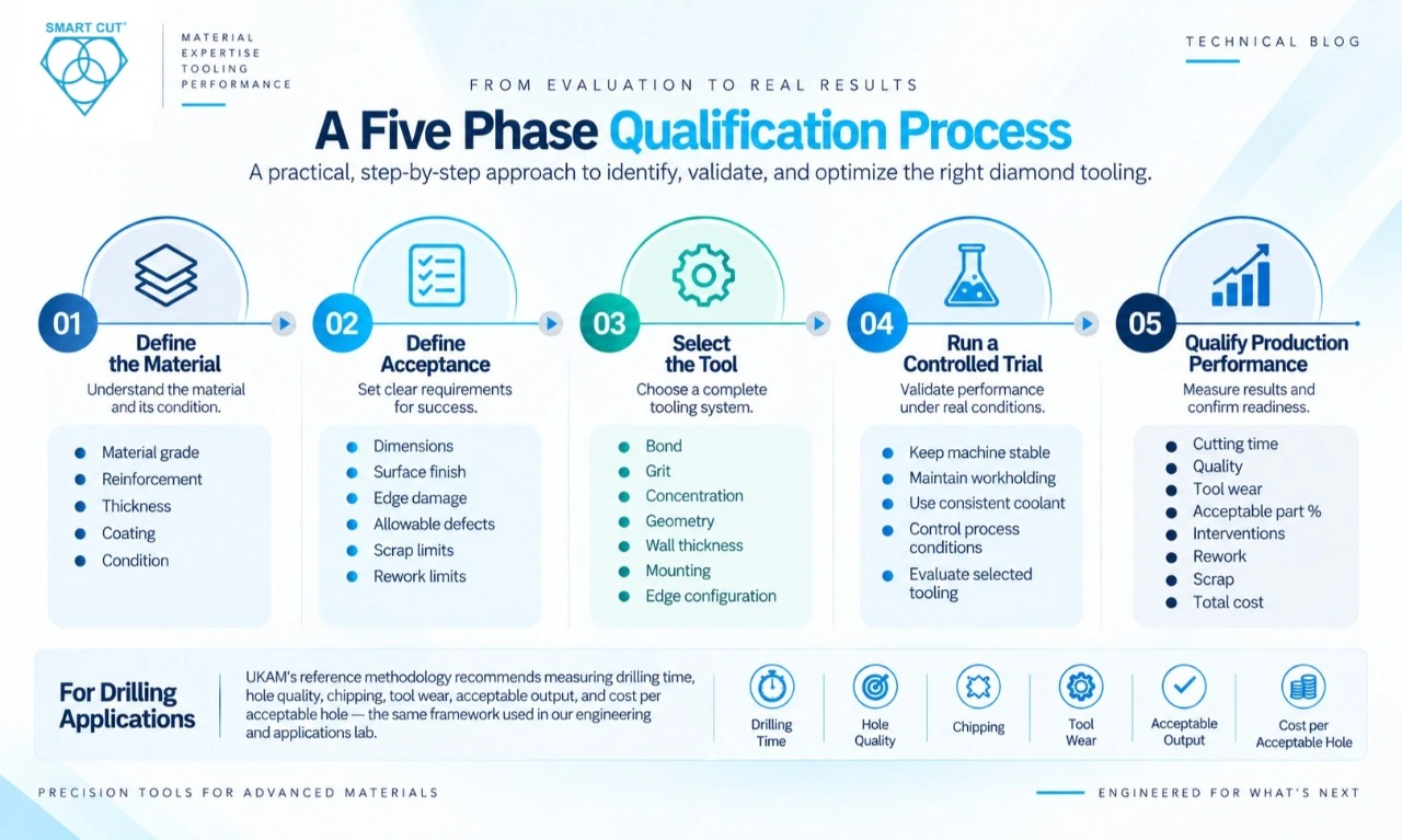
- Phase 1: Define the material. Record material grade, reinforcement, thickness, coating, and condition.
- Phase 2: Define acceptance. Specify dimensions, surface finish, edge damage, allowable defects, scrap limits, and rework limits.
- Phase 3: Select the tool. Choose bond, grit, concentration, geometry, wall thickness, mounting, and edge configuration as one system.
- Phase 4: Run a controlled trial. Keep machine, workholding, coolant, and process conditions stable while evaluating the selected tooling.
- Phase 5: Qualify production performance. Measure cutting time, quality, tool wear, acceptable part percentage, interventions, rework, scrap, and total cost.
For drilling applications, UKAM’s reference methodology specifically recommends measuring drilling time, hole quality, chipping, tool wear, acceptable output, and cost per acceptable hole — the same framework used in UKAM’s engineering and applications lab.
What to Ask a Diamond Tool Supplier
The quality of the supplier’s engineering response is itself useful evidence.
|
Ask the supplier |
What the answer reveals |
|---|---|
|
What bond do you recommend and why? |
Whether material wear has been considered |
|
What grit and concentration? |
Whether cutting and finish were evaluated together |
|
What failure mode is the tool designed to address? |
Whether the recommendation is application specific |
|
What information do you need from us? |
Depth of engineering evaluation |
|
How should tool life be measured? |
Whether quality is included in tool life |
|
What machine information is required? |
Awareness of process interaction |
|
Can the geometry be customized? |
Manufacturing flexibility — see custom diamond & CBN tool manufacturing |
|
What should we measure during the trial? |
Qualification methodology |
|
How should worn tools be inspected? |
Understanding of wear mechanisms — see dressing stick selection guide |
A supplier should be able to discuss the relationship between the abrasive, bond, workpiece, machine, and production objective rather than simply recommending a standard diameter. You can put these questions directly to UKAM’s applications engineers through the contact page.
When Custom Diamond Tooling Makes Sense
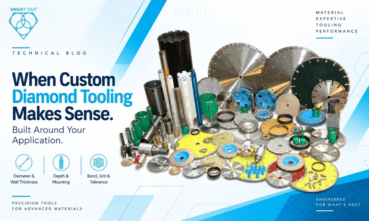
Standard tooling is appropriate when the application fits an available specification, such as those listed in the full diamond and CBN product catalog.
Custom tooling becomes more useful when the process requires a combination that a standard tool cannot provide. Typical triggers include nonstandard diameter, restricted wall thickness (see an example thin-wall sintered core drill specification), unusual drilling depth, special mounting, tight dimensional tolerance, specialized edge configuration, unusual composite construction, and production requirements that justify a dedicated tool.
UKAM states that custom diamond drills and tools can be produced according to customer drawings or specifications, including dimensions, wall thickness, drilling depth, mounting, bond type, diamond size, concentration, and tolerances — full detail is available on the diamond core drill manufacturer & supplier page.
UKAM Tooling Technologies Compared
The following comparison summarizes the tooling categories described in UKAM’s technical material, drawn from the full diamond industry solutions overview.
|
Tool technology |
Primary characteristic |
Application consideration |
|---|---|---|
|
Sintered diamond |
Multiple abrasive layers within matrix |
Useful where controlled wear and repeat production matter |
|
Electroplated diamond |
Exposed diamond on supporting body |
Useful where open cutting action and specialized geometry are required |
|
Brazed diamond |
Strong retention of exposed diamond |
Suitable for selected high stock removal and composite applications |
|
Diamond grinding wheels |
Abrasive wheel construction for grinding |
Select according to material, finish, removal rate and wear — see core drill and grinding wheel range |
|
CVD diamond |
Defined diamond material or surface |
Specialized precision applications |
|
PCD |
Polycrystalline diamond cutting material |
Applications requiring a defined cutting edge |
UKAM identifies sintered metal, nickel plated, brazed, CVD, and PCD constructions within its diamond tooling range, with selection dependent on the material and application. See also the diamond and CBN wafering blade specifications for a construction comparison on the cutting side.
The comparison should be treated as a starting point for qualification, not as a universal ranking.
Composite Tool Qualification Checklist
Material
- Exact composite identified
- Fiber type recorded
- Matrix identified
- Fiber content documented
- Material thickness recorded
- Coatings and surface condition documented
Tool
- Operation defined
- Bond selected
- Diamond grit selected
- Concentration selected
- Tool geometry selected
- Mounting verified
- Edge configuration reviewed
Quality
- Dimensional tolerance defined
- Edge damage limit defined
- Surface finish defined
- Scrap limit defined
- Rework limit defined
Machine
- Spindle capability checked
- Runout measured
- Rigidity reviewed
- Workholding verified
- Machine alignment verified
- Coolant delivery checked — reference the integral coolant recirculation system used on precision sectioning saws
Production
- Cycle time measured
- Tool life measured
- Tool changes recorded
- Acceptable part rate calculated
- Scrap cost calculated
- Rework cost calculated
- Cost per acceptable part calculated
New to navigating UKAM’s catalog while working through this checklist? The site navigation and product-filtering guide shows how to move between industry, material, and specification filters efficiently.
Frequently Asked Questions
No. Composite materials differ significantly in reinforcement, matrix, fiber orientation, hardness, abrasiveness, and structure. CFRP, GFRP, aramid, honeycomb, CMC, and MMC can produce different failure mechanisms. Tool construction should therefore be selected from the specific material and operation rather than from the general category of “composite.”
There is no single specification that is best for every CFRP application. Cutting, drilling, and grinding have different requirements. The selection should consider fiber orientation, laminate structure, required edge quality, dimensional tolerance, production rate, tool wear, and machine conditions.
Coarse grit can support more aggressive material removal, while fine grit can support finer surface interaction and edge control. Neither should be selected independently of bond, concentration, tool geometry, feed, and production requirements. The correct grit is the one that produces the required quality while maintaining useful cutting efficiency and tool life.
First determine where the damage begins. Entry damage, exit damage, and damage throughout the operation can point toward different process variables. Check tool condition, runout, workholding, feed, engagement, support, coolant, and tool construction before assuming that the diamond grit is incorrect.
Measure tool life by the number of acceptable parts produced within specification. Physical tool survival is not sufficient if the tool has already caused unacceptable dimensions, surface damage, delamination, or rework. This approach also provides a better basis for calculating production cost.
No. A higher tool price can be justified when it produces more acceptable parts, reduces scrap, lowers tool change frequency, or shortens the complete production cycle. The correct comparison is total cost per acceptable part rather than purchase price alone.
Consider custom tooling when a standard tool cannot provide the required geometry, mounting, reach, tolerance, edge configuration, or production performance. Before ordering a custom tool, verify that the actual problem is not caused by machine runout, workholding, coolant, or process instability.
Not necessarily. Each operation creates different abrasive engagement, material removal, heat generation, and dimensional requirements. A diamond cutting blade, diamond core drill, and diamond grinding wheel should be specified according to the operation and the failure mode being controlled.
More questions on specification, lead time, or custom quoting are answered in full on UKAM’s general FAQ page.
Final Engineering Principles
- Select the tool from the composite structure and machining operation, not the material name alone.
- Define the finished quality requirement before selecting abrasive specifications.
- Treat bond, grit, concentration, geometry, and machine conditions as one system.
- Diagnose the failure mode before changing tooling.
- Measure tool life by acceptable production, not physical tool survival.
- Compare suppliers using cost per acceptable part, not tool price alone.
- Keep cutting, drilling, and grinding requirements separate when selecting diamond tooling.
- Use controlled trials so individual tooling variables can be evaluated, drawing on UKAM's R&D and applications testing capability.
- Consider custom tooling when standard geometry creates a measurable production limitation.
The best diamond tool is the one that delivers the required quality, process stability, tool life, and production cost under the actual machine conditions — the same standard UKAM applies across its full diamond and CBN tool manufacturing range.
Trusted by Tens of Thousands of Manufacturers, Laboratories,
Research Institutions Worldwide Since 1990
American Based Manufacturer
Established in 1990
