








































Grinding Wheel and Machine Troubleshooting

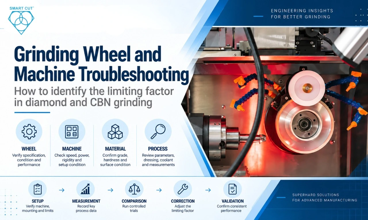
Table of Contents
Toggle
American Based Manufacturer

Established in 1990


Custom manufacturing


How to identify the limiting factor in diamond and CBN grinding
When grinding produces chatter, excessive load, poor finish, short wheel life, or dimensional variation, begin with a controlled comparison. Verify the setup, define the failed requirement, and determine whether the result follows the wheel, the machine, the material, or a particular combination.
A suitable wheel must work within the speed, power, rigidity, dressing, and coolant capabilities of your production equipment. Matching the wheel to those conditions is part of selecting the right tool. A wheel that performs well on another machine may still need a different specification for your application.
This guide explains how to collect useful evidence, interpret the main measurements, and choose the next corrective action. The method applies to diamond and CBN grinding, with maintenance procedures adapted to the wheel construction.
Start with the pattern of the problem
Use the following observations to choose an initial check. Each pattern suggests an investigation. It does not establish a cause by itself.
|
Observed pattern |
Useful first check |
|---|---|
|
Quality deteriorates after a repeatable number of parts |
Compare wheel condition, loading, coolant condition, and time since approved conditioning. |
|
The problem begins after a wheel change |
Check mounting, actual diameter, setup offsets, wheel specification, and starting surface condition. |
|
Different wheels perform poorly on one machine |
Check the shared setup, spindle, workholding, dressing, coolant, and operating capacity. |
|
The problem begins with a new material batch |
Verify grade, hardness, stock allowance, surface condition, and material geometry. |
|
Only one wheel and machine combination performs poorly |
Investigate compatibility and interactions between the wheel specification and machine conditions. |
A practical sequence for controlled troubleshooting
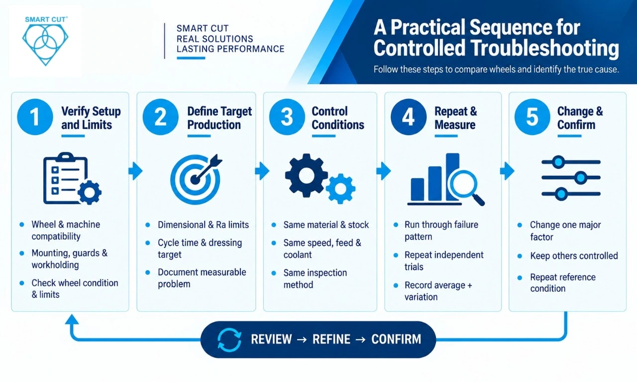
1. Verify the setup and operating limits
Before a trial, confirm that the wheel construction, dimensions, mounting arrangement, and intended operation are compatible with the machine. Check the approved speed limits for the wheel and complete setup. A speed calculation does not authorize operation beyond those limits.
Perform mounting and static inspection with the machine stopped and energy isolated according to the equipment procedure. Verify guards, wheel condition, clean mounting surfaces, correct seating, and secure workholding. Stop a trial if vibration, damage, or loading reaches a defined stop condition. Do not keep running an unsafe setup simply to reproduce a failure.
2. Define acceptable production before comparing wheels
Record the dimensional limits, surface finish requirement, edge or surface defects allowed, and any required surface-integrity inspection. Define the production target separately, including cycle time, dressing interval, wheel consumption, and scrap.
Use a measurable problem statement. For example, an illustrative trial could show roughness increasing from 0.40 to 0.58 µm Ra after 70 parts against a maximum requirement of 0.50 µm Ra. Record the material, operation, measurement method, and wheel condition so the result can be reproduced.
If you have an acceptable production condition, document it as the reference. If no condition has ever met the requirements, use the current setup as a documented starting point. Do not describe an unqualified process as a known acceptable baseline.
3. Keep the comparison conditions consistent
Control material batch, stock allowance, actual wheel surface speed, feed, depth, coolant, workholding, and the initial wheel condition. Record changes introduced by remounting or conditioning. The same programmed settings do not guarantee the same physical contact or removal rate on different machines.
Use the same inspection procedure and instrument settings. For surface roughness, record the measurement direction and applicable sampling or filter settings. Check measurement repeatability before interpreting a small difference as a process improvement.
4. Repeat the reference and the changed condition
Run long enough to investigate the failure pattern within approved limits. If deterioration normally appears after several dressing cycles, a few good parts immediately after dressing will not answer the question. Record results at planned points through the cycle.
Repeat the comparison to distinguish a consistent effect from ordinary variation. The number of trials depends on the observed variability and the consequence of an incorrect decision. Show the spread of the results as well as their average. Several measurements on one part do not replace independent production trials.
5. Change a defined factor and confirm the result
Changing one major factor at a time is useful for initial troubleshooting. State what changed and what remained controlled. Where compatible with wheel life and safe operation, repeat the reference condition afterward to check for drift caused by warm-up, wear, material, or coolant.
Some improvements depend on combinations of factors. If speed, dressing, and wheel specification interact, use a planned experiment that can examine those interactions. Research on sapphire grinding has shown that the factors affecting force and surface defects can interact and influence different responses differently. See the published study on sapphire grinding.
Compare two wheels on two machines when practical
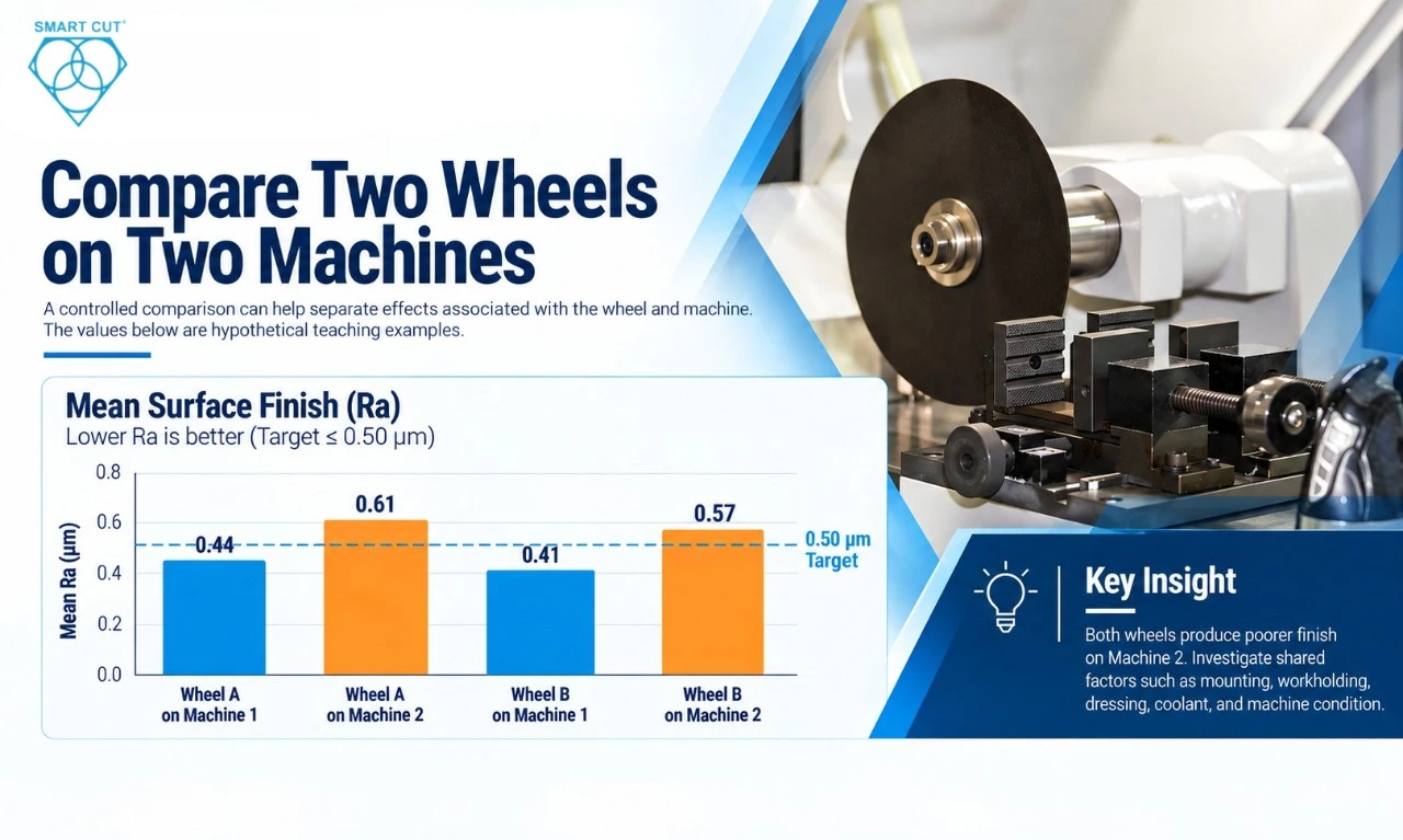
A controlled comparison can help separate effects associated with the wheel and machine. The following values are hypothetical teaching examples, not UKAM production data or recommended process limits. Assume a finish requirement of Ra no greater than 0.50 µm. All other part requirements must also pass.
|
Combination |
Mean Ra (µm) |
Observed range (µm) |
Finish result |
|---|---|---|---|
|
Wheel A on Machine 1 |
0.44 |
0.42 to 0.46 |
Pass |
|
Wheel A on Machine 2 |
0.61 |
0.58 to 0.64 |
Fail |
|
Wheel B on Machine 1 |
0.41 |
0.39 to 0.43 |
Pass |
|
Wheel B on Machine 2 |
0.57 |
0.54 to 0.60 |
Fail |
In this example, each combination represents three separate trial runs. The mean and range summarize one representative Ra result from each run. Three runs illustrate the reporting method and are not a universal qualification sample size.
Both wheels produce poorer finish on Machine 2. Investigate what they share there, including mounting, workholding, dressing, coolant, and machine condition. The table does not identify a specific defect or prove that the machine hardware is responsible.
If Wheel A repeatedly fails on both machines while Wheel B passes, investigate Wheel A’s specification and condition. Distinguish an individual damaged or incorrectly prepared wheel from a problem with the complete specification. If the ranking changes between machines, examine compatibility between wheel and machine conditions.
Maintain comparable starting conditions and account for trial order. Moving the same physical wheel introduces remounting and wear effects. Using separate nominally identical wheels introduces variation between individual wheels. Record which approach you use.
Use a reference comparison if you have one machine
Start with a wheel and setup that previously produced acceptable parts, if available. Confirm material and inspection consistency, then repeat that reference under the present conditions. If the reference also deteriorates, investigate factors shared by both wheels before attributing the result to the new specification.
Inspect the setup, make one justified correction, and repeat the trial. If the reference still performs well but the candidate wheel does not, review the candidate’s specification, condition, and required operating window. A second wheel of the same specification can help investigate an individual-wheel issue.
A single-machine comparison narrows the investigation, but cannot isolate every machine interaction. Record that limitation. When comparing different wheel technologies, distinguish a controlled comparison at common settings from a comparison of separately optimized processes. The latter evaluates the complete production method.
Measure force and power correctly
Grinding force has direction. Normal force acts perpendicular to the local contact surface and contributes to deflection and workholding loads. Tangential force acts along the local cutting direction and relates to the mechanical power required at the wheel. Identify the component, measurement location, and whether values are averages or peaks.
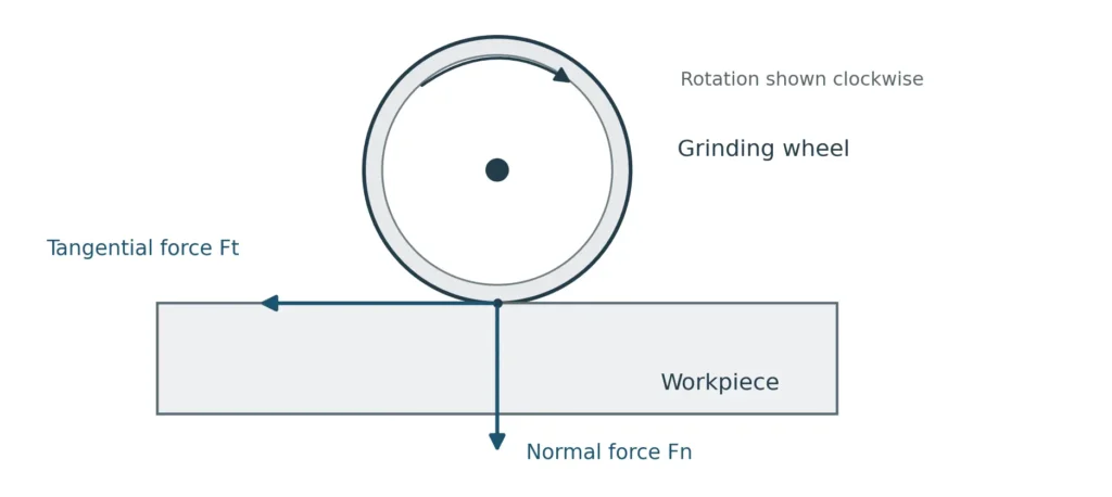
Forces shown act on the workpiece at an idealized contact. Forces on the wheel act in opposite directions. The schematic is not a mounting or machine setup drawing.
Mechanical grinding power at the wheel is related to tangential force by P = Ft × vs. With Ft in newtons and wheel surface speed vs in meters per second, P is in watts. Motor electrical input also includes losses and should not be treated as identical to mechanical grinding power.
P = Ft × vs → 145 N @ 4,000 sfm ≈ 2.95 kW | 112 N @ 7,500 sfm ≈ 4.27 kW
These illustrative calculations show why lower force alone does not prove lower power demand or lower thermal risk.
If you do not have a force sensor, begin with available spindle-load trends, cycle time, finish, dimensions, dressing intervals, and scrap. These measurements are useful indicators. They do not directly measure normal grinding force.
Interpret the spindle display on its own terms
Check what the displayed load percentage represents and how it is scaled. Record the reference rating, sampling or averaging behavior, actual operating speed, and whether the reading is a peak or sustained value. A percentage from one machine is not automatically comparable with the same percentage on another.
Review available power and torque at the speed used, including continuous and short-duration ratings. Compare loaded speed with commanded speed where this measurement is available. If load rises as the wheel loses cutting ability, both wheel condition and machine capacity may be involved. Do not use an illustrative percentage as a universal overload limit.
Check wheel speed against the actual diameter
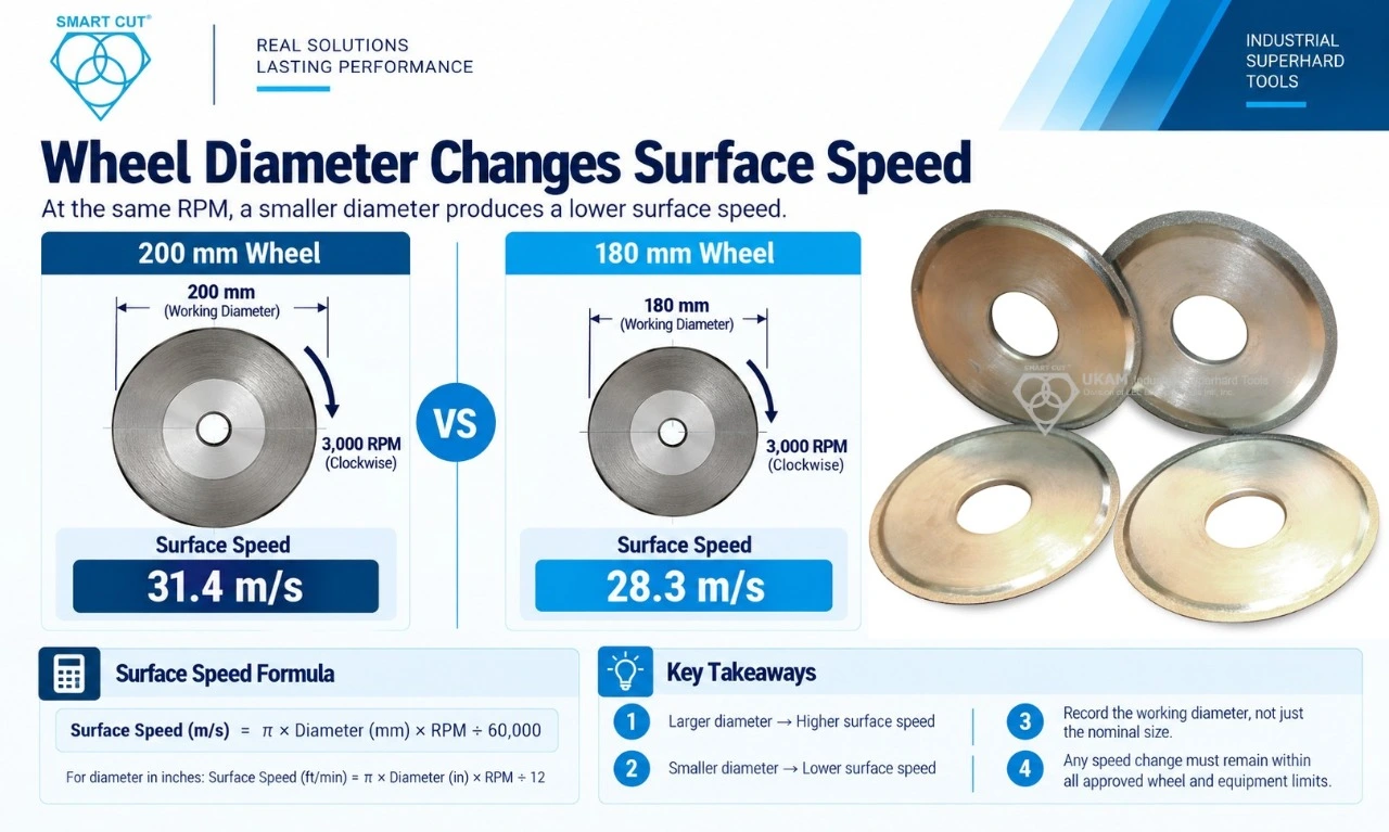
Wheel surface speed depends on both diameter and RPM. Record the working diameter rather than relying only on the nominal size. At unchanged RPM, a smaller diameter produces a lower surface speed.
For diameter in millimeters, surface speed in m/s = π × diameter × RPM ÷ 60,000. For diameter in inches, surface speed in feet per minute = π × diameter × RPM ÷ 12.
As a calculation example, a 200 mm wheel at 3,000 RPM runs at approximately 31.4 m/s. At 180 mm and the same RPM, surface speed is approximately 28.3 m/s. These values are not operating recommendations. Any speed compensation must remain within all approved wheel and equipment limits.
Higher speed can change chip formation, force, wear, coolant access, and heat generation. It does not guarantee a better result. Qualify a speed change against all part requirements and production measures. If the machine cannot reach an appropriate operating window, consider a different wheel specification or process plan suited to the available equipment.
Separate mounting error from spindle and workholding problems
Periodic marks or vibration justify investigation of the rotating assembly and process dynamics. Runout, imbalance, unstable contact, workpiece motion, and chatter are different conditions. A repeating surface pattern does not identify the source by itself.
|
Check |
What to document |
|---|---|
|
Spindle or arbor runout |
Specified reference surface, radial or axial direction, instrument resolution, and measurement procedure. |
|
Flange face and mounting |
Cleanliness, seating, face condition, correct fit, and the approved tightening procedure. |
|
Mounted wheel accuracy |
Measurement location, wheel condition, and result before or after approved truing where applicable. |
|
Workholding and support |
Part overhang, support positions, clamping method, and evidence of movement or deformation. |
|
Vibration and stability |
Speed, contact condition, load, part location, and whether the pattern changes with a controlled adjustment. |
Compare runout with the relevant equipment specification and the needs of the operation. A single runout limit cannot cover every wheel size, contact geometry, and tolerance. Follow the approved method for checking an abrasive surface rather than assuming a rough surface gives a reliable indicator reading.
On suitable wheels, truing can correct wheel geometry relative to the spindle axis. It does not repair bearing motion or a damaged spindle. Static runout readings also do not fully characterize dynamic behavior under load.
For thin or flexible workpieces, evaluate both movement during grinding and distortion from clamping. A part can appear secure and still deflect. Inspect dimensions after release when that is relevant to the drawing requirement. Do not assume additional clamping force is always the correct response.
Match conditioning to the wheel construction
Truing establishes wheel shape and running accuracy. Dressing or sharpening conditions the abrasive surface for cutting. Depending on construction and equipment, these may be separate operations or part of a combined procedure.
For resin, vitrified, metal, and hybrid bonded wheels, confirm the approved conditioning tool, method, depth, speed, and coolant requirements for that specific wheel. A method suitable for one construction may be ineffective or damaging on another.
Single-layer electroplated diamond and CBN wheels do not contain successive abrasive layers that conventional dressing can expose. Do not apply bonded-wheel dressing procedures to them. Use only an approved cleaning or conditioning method. Damage or loss of the abrasive layer may require replacement or evaluation for recoating.
For a dressable wheel, compare load and quality before and after controlled conditioning. A repeatable recovery directs attention to wheel surface condition and the conditioning interval. It does not establish why the wheel deteriorated. Check loading, coolant, bond suitability, removal rate, and conditioning effectiveness before increasing dressing frequency.
Verify coolant at the contact and material at the start
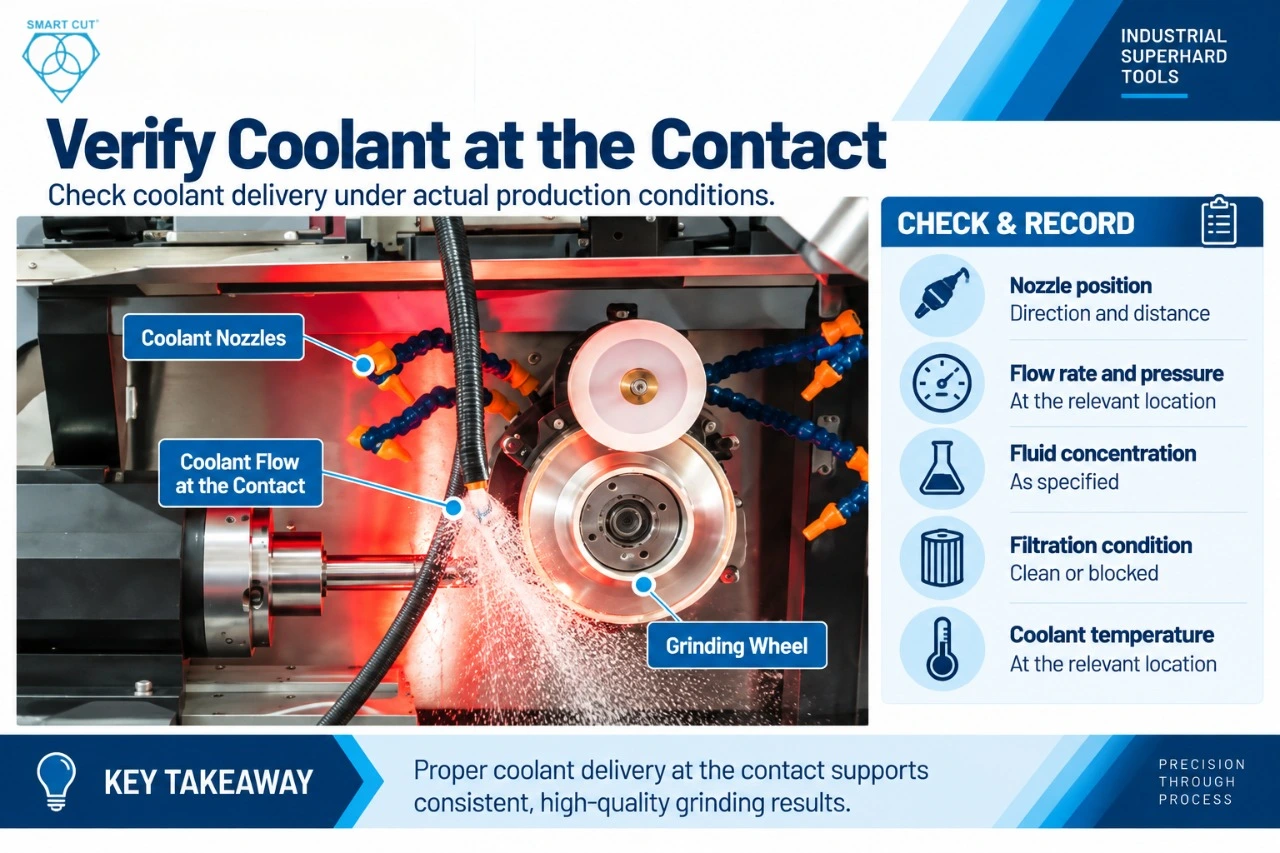
Check whether coolant reaches the working contact consistently under actual production conditions. Pump capacity alone does not establish effective delivery. Record nozzle position, flow, pressure at the relevant location, fluid concentration, filtration condition, and temperature.
Use the approved procedure for checking delivery. Correct nozzle placement or a blocked filter may matter more than increasing pressure. Any adjustment must suit the wheel, machine, enclosure, and fluid system. Compare quality and load before and after the correction while holding the other trial conditions steady.
When a problem starts with a material batch, verify the grade, hardness where applicable, heat treatment, stock allowance, surface condition, and geometry. Keep a reference batch for comparison where practical. Material variation can change grinding behavior even when the program is unchanged.
For ceramic and glass applications, define the required inspection for chipping, cracking, and subsurface damage where relevant. For heat-sensitive hardened materials, define the required thermal-damage inspection. Acceptable Ra or an absence of visible discoloration alone does not establish acceptable surface integrity.
For related guidance, see coolant selection for diamond and CBN tools and the diamond and CBN wheel troubleshooting guide.
Choose the corrective action from the evidence
A wheel change is justified when repeatable comparisons show that the existing wheel cannot meet the required quality or production target within the available operating window. Review abrasive type, grit, concentration, bond, geometry, and conditioning response together. Define the expected improvement before selecting the next trial.
Diamond and CBN are not interchangeable choices. Diamond is widely used for carbide, ceramics, and glass. CBN is commonly used for hardened ferrous materials. The material grade, operation, required finish, and machine conditions still determine the appropriate specification.
If several wheels fail only under the same setup, correct the shared limitation first where the evidence supports that action. If the limitation is an inherent equipment capability, a wheel designed for lower forces or a different contact geometry may be a valid solution. Confirm the result through testing. A change in wheel specification cannot make an unsafe or defective setup acceptable.
For example, poor finish in precision ceramic grinding may require investigation of support, contact geometry, wheel condition, and coolant alongside grit selection. High load during CBN grinding of hardened steel may involve conditioning, stock allowance, and available torque. Treat these as investigation paths, not predetermined diagnoses.
Compare cost per acceptable part
Once quality requirements are met, compare total production cost. Include the time and consumables needed to achieve that quality. Longer wheel life or a lower wheel price does not by itself identify the lower-cost process.
The following example is hypothetical. Each option processes 1,000 blanks at $20 per blank. The combined machine and labor rate is $120 per hour. Cycle time excludes dressing and allocated setup time, which are added separately. Wheel cost is the amount consumed or allocated to this batch. Accepted parts meet the same requirements, and rejected parts receive no recovery credit.
|
Cost or production measure |
Wheel A |
Wheel B |
|---|---|---|
|
Attempted parts |
1,000 |
1,000 |
|
Accepted parts |
990 |
978 |
|
Grinding cycle per attempted part |
60 seconds |
75 seconds |
|
Total grinding time |
1,000 minutes |
1,250 minutes |
|
Dressing time |
12 × 3 = 36 minutes |
9 × 3 = 27 minutes |
|
Allocated setup and wheel-change time |
20 minutes |
20 minutes |
|
Total machine and labor time |
1,056 minutes |
1,297 minutes |
|
Machine and labor cost |
$2,112 |
$2,594 |
|
Allocated wheel cost |
$300 |
$240 |
|
Blank cost for all attempted parts |
$20,000 |
$20,000 |
|
Total included batch cost |
$22,412 |
$22,834 |
|
Cost per acceptable part |
$22.64 |
$23.35 |
Divide the total included batch cost by accepted parts. Although Wheel B has a lower allocated wheel cost and needs fewer dressing events, its longer cycle and greater scrap make it approximately $0.71 more expensive per acceptable part in this example.
Add any material differences in inspection, coolant, rework, disposal, and other costs in your own calculation. Do not count labor twice if it is already included in the machine rate. Record the cost assumptions so comparisons remain consistent.
Record the result so it can be reproduced
Keep one trial record linking the material and wheel identification to the setup, measured operating conditions, conditioning history, and inspection results. Include the starting state, change made, trial order, number of runs, and any interruptions or departures from the plan.
End the record with a clear decision: the change met the requirements, failed them, or produced inconclusive evidence. Document the next action and the conditions approved for production. A promising short trial should remain a trial until the required repeatability and production duration have been demonstrated.
Questions that often arise during troubleshooting
Yes. Abrasive compatibility does not establish a complete production specification. The wheel must also suit the available speed, power, support, conditioning, coolant, and contact geometry. Selection should account for those requirements from the start.
No. Common settings can support a controlled initial comparison when they are appropriate and approved for both wheels. A different wheel technology may need different conditions. Report an optimized comparison as a comparison of complete processes, with every changed factor documented.
No. Finish is one requirement. Dimensions, form, edge condition, surface integrity, stability, and production cost may also determine acceptance. Use the drawing and application requirements to define the inspection plan.
Request help with your grinding application
UKAM Industrial Superhard Tools manufactures diamond and CBN tools for precision grinding applications. We can help review how the wheel specification matches your material, machine, and production requirements.
To begin, provide your material and grinding operation, current wheel specification and dimensions, machine and available speed range, current settings, and the main problem with its acceptance limit. A photograph of the setup and representative part defects can also help. Include load or inspection records if available. Additional measurements can be identified during the review.
Trusted by Tens of Thousands of Manufacturers, Laboratories,
Research Institutions Worldwide Since 1990
American Based Manufacturer
Established in 1990
