






















Industrial Diamond Core Drills: Selection, Specifications, and Tool-Life Qualification

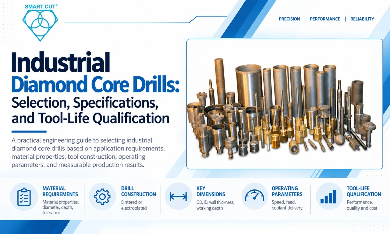
Table of Contents
Toggle
American Based Manufacturer

Established in 1990


Custom manufacturing


Industrial diamond core drills are used to produce holes in hard, brittle, abrasive, and composite materials where hole geometry, edge quality, and dimensional consistency are critical. Selecting the right drill requires more than matching its nominal diameter to the required hole.
Material properties, drill construction, working depth, mounting interface, machine capability, coolant delivery, and production requirements all influence the final specification.
For manufacturing and process engineers, the objective is to select a tool that produces acceptable holes consistently under defined production conditions. This guide explains how to specify industrial diamond core drills, compare two UKAM SMART CUT® series, establish a qualification process, and evaluate tool performance using measurable production results.
Define the Application Before Selecting a Drill
Begin with the finished hole requirements. A drill that cuts quickly is not necessarily suitable if it produces unacceptable edge damage, inconsistent dimensions, or excessive secondary finishing.
Document the following information before requesting a quotation or selecting a stock tool.
|
Requirement |
Information to record |
|---|---|
|
Workpiece material |
Material name, grade, composition, and condition |
|
Hole diameter |
Nominal diameter and required tolerance |
|
Hole depth |
Required depth and whether the hole is through or blind |
|
Workpiece geometry |
Thickness, dimensions, and available support |
|
Edge quality |
Permitted entry and exit chipping or breakout |
|
Bore requirements |
Diameter consistency, taper, roundness, and surface finish where specified |
|
Machine |
Spindle speed range, feed control, rigidity, and runout |
|
Mounting interface |
Spindle connection, thread, shank, and adapter requirements |
|
Delivery method and any material or cleanliness restrictions |
|
|
Production target |
Required output, cycle-time objective, and batch size |
These details provide a basis for comparing tools against the actual application rather than relying on general descriptions such as “high performance” or “long tool life.”
Selection principle: Define how the finished hole will be inspected and accepted before comparing candidate drills.
Compare Diamond Core Drill Constructions
The bond system retains the diamond abrasive and influences how the cutting surface behaves during use. Sintered metal-bond and multi-layer electroplated constructions are two options engineers may evaluate, depending on the material and application.
115DE SMART CUT® Series: Sintered Metal Bond
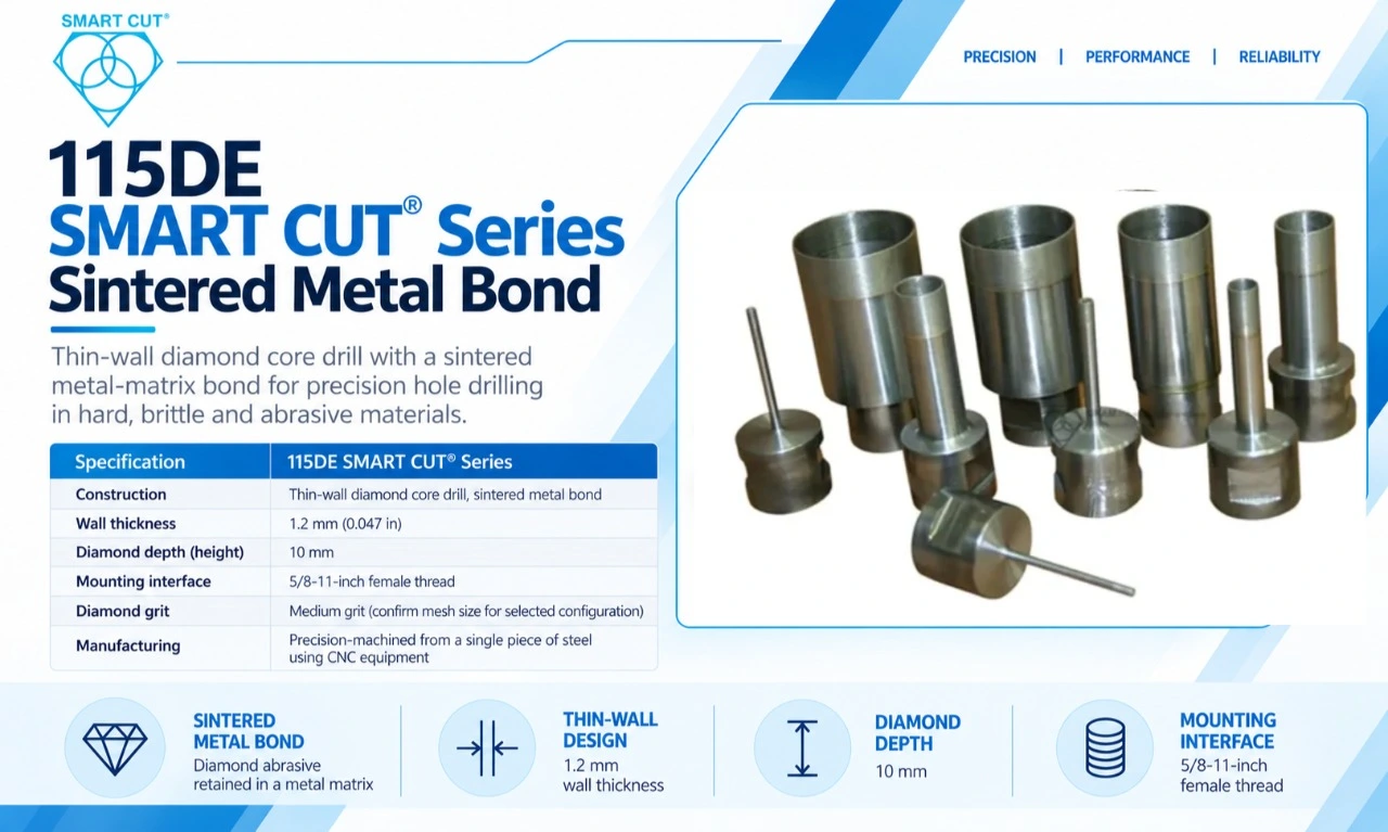
UKAM’s 115DE SMART CUT Series is a thin-wall diamond core drill with a sintered metal-matrix bond.
According to the supplied product description, the series has the following specifications:
|
Specification |
115DE SMART CUT Series |
|---|---|
|
Construction |
Thin-wall diamond core drill, sintered metal bond |
|
Wall thickness |
1.2 mm (0.047 in) |
|
Diamond depth (height) |
10 mm |
|
Mounting interface |
5/8-11-inch female thread |
|
Diamond grit |
Medium grit; exact mesh size should be confirmed for the selected configuration |
|
Manufacturing |
Precision-machined from a single piece of steel using CNC equipment |
UKAM lists applications including glass, alumina, quartz, ruby, YAG, silica, silicon, graphite, composites, and other non-metallic ceramics.
The sintered metal matrix retains the diamond abrasive within the tool structure. For an actual application, confirm the available drill diameter, dimensional tolerances, and required configuration with UKAM before ordering.
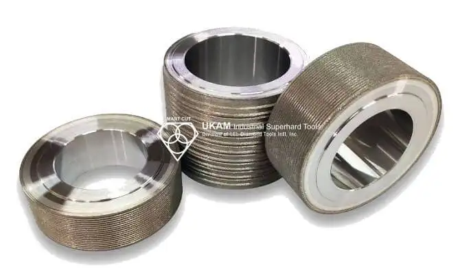
105DE SMART CUT® Series: Multi-Layer Electroplated
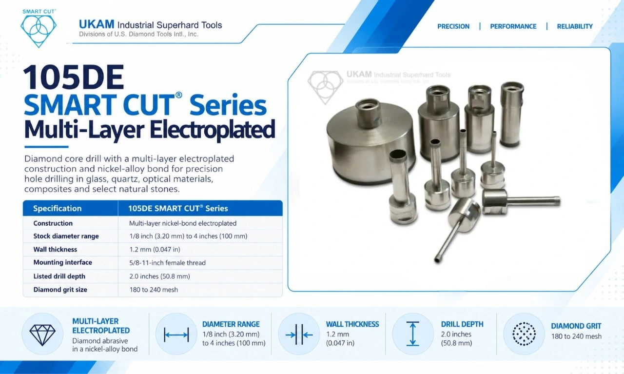
UKAM’s 105DE SMART CUT Series uses a multi-layer electroplated diamond construction with a nickel-alloy bond.
Its published series specifications include:
|
Specification |
105DE SMART CUT Series |
|---|---|
|
Construction |
Multi-layer nickel-bond electroplated |
|
Stock diameter range |
1/8 inch (3.20 mm) to 4 inches (100 mm) |
|
Wall thickness |
1.2 mm (0.047 in) |
|
Mounting interface |
5/8-11-inch female thread |
|
Listed drill depth |
2.0 inches (50.8 mm) |
|
180 to 240 mesh |
UKAM lists applications including glass, quartz, optical materials, composites, and certain natural and semi-precious stones.
The product page also recommends compatible water-swivel adapters for coolant delivery. Confirm the appropriate adapter and mounting arrangement for the selected drill and machine.
These specifications describe the listed 105DE series. Verify the exact dimensions and configuration required for the individual application.
How to choose between the constructions
Do not select a drill solely because it is sintered or electroplated. Compare the complete configuration against the material, hole dimensions, quality requirements, machine setup, and expected production conditions.
|
Selection factor |
What engineers should evaluate |
|---|---|
|
Material compatibility |
Suitability for the exact material grade and workpiece condition |
|
Hole geometry |
Required diameter, depth, tolerance, and core clearance |
|
Bond construction, grit, wall thickness, and usable working depth |
|
|
Machine compatibility |
Mounting interface, runout, available speed range, and feed control |
|
Production requirements |
Hole quality, cycle time, tool interventions, and accepted output |
For additional configurations, see UKAM’s diamond core drills and bits catalog.
Specify Diameter, Wall Thickness, and Working Depth
Once a suitable construction has been identified, confirm the tool geometry.
The outside diameter (OD) defines the external cutting diameter. The inside diameter (ID) defines the internal opening and influences the core dimensions.
Specify the required finished hole diameter and tolerance first. Then confirm the drill’s actual dimensions and suitable configuration with the manufacturer. Do not assume that nominal drill diameter automatically equals the final measured hole diameter.
Wall thickness affects the width of the annular cut and the geometry of the tool. It should be considered alongside diameter, material, rigidity, and the required hole quality.
A thinner wall may reduce the amount of material removed per revolution, but it does not automatically guarantee better edge quality or longer tool life. Qualification under the intended operating conditions is necessary.
These terms describe different dimensions:
- Diamond depth or height: the axial extent of the diamond-bearing region.
- Usable drilling depth: the depth the drill is designed to achieve under the specified configuration.
- Overall length: the tool's total physical length.
Do not treat these measurements as interchangeable. For deep holes, confirm the usable working depth, coolant access, debris evacuation, and core-removal method.
Verify the complete connection between spindle and tool, including any adapter or coolant-delivery assembly. A matching thread alone does not establish that the full setup is compatible.
Check tool alignment and spindle runout before qualification. Uneven engagement can affect dimensional consistency, edge damage, and wear.
Match the Drill to the Workpiece Material
Material category is a starting point, not a complete selection criterion. Composition, hardness, thickness, reinforcement, and acceptance requirements may change the tool and process requirements.
|
Material group |
Primary selection considerations |
|---|---|
|
Advanced ceramics, including alumina and zirconia |
Brittleness, hardness, edge-damage limits, and dimensional accuracy |
|
Glass and quartz |
Chipping, workpiece support, coolant delivery, and bore quality |
|
Material-specific cutting behavior, surface damage, and dimensional control |
|
|
Semiconductor materials and substrates |
Substrate integrity, material grade, cleanliness, and dimensional requirements |
|
Carbon- and glass-fiber composites |
Fiber orientation, matrix behavior, reinforcement structure, and delamination risk |
|
Graphite and other abrasive non-metallic materials |
Abrasiveness, debris evacuation, and tool wear |
Use this table to establish trial priorities, not to assume that a particular drill series will perform identically across all materials in a category.
UKAM provides further application information for advanced ceramics, semiconductor materials, and composites.
Establish Operating Parameters
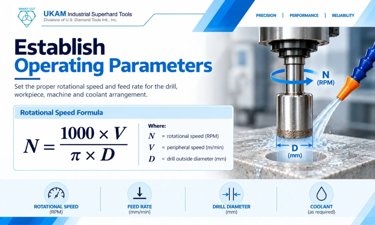
Rotational speed and feed rate must be appropriate for the selected drill, workpiece, machine, and coolant arrangement. They should not be inferred from drill diameter alone.
The relationship between peripheral speed and rotational speed is:
Where:
N = rotational speed in revolutions per minute (RPM)
V = peripheral speed in metres per minute (m/min)
D = drill outside diameter in millimetres (mm)
Illustrative RPM calculation
For a 20 mm drill at a hypothetical peripheral speed of 20 m/min:
N = 1000 × 20π × 20 ≈ 318 RPM
This is a mathematical example, not an operating recommendation for the 115DE or 105DE series. Establish starting conditions from the manufacturer’s guidance and confirm that the machine and setup can support them.
Feed rate, coolant delivery, workpiece support, and machine condition should be evaluated as part of the same process setup. Record the actual conditions used during qualification so the result can be reproduced.
For detailed operating guidance, consult UKAM’s diamond core drill speed chart for ceramics, glass, sapphire, and quartz and diamond core drill best practices.
Qualify the Drill Against Measurable Criteria
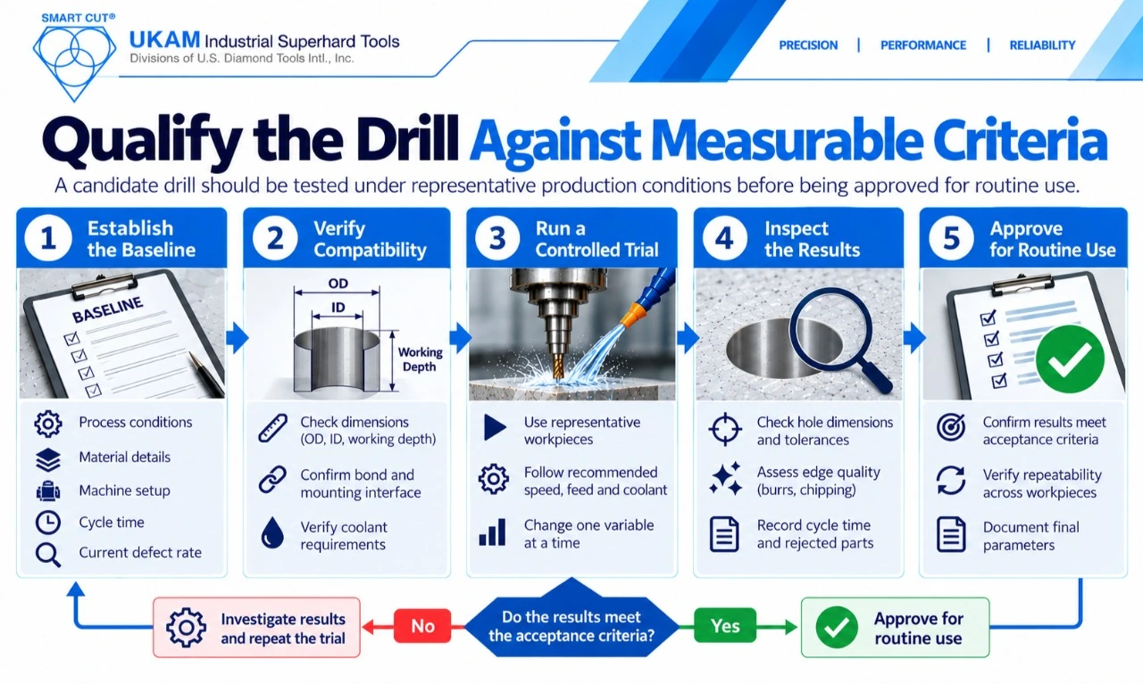
A candidate drill should be tested under representative production conditions before being approved for routine use.
Phase 1: Establish the baseline
Document the existing process, if one exists. Record the tool specification, workpiece material, machine setup, coolant arrangement, cycle time, inspection method, and current defect rate.
If no existing process is available, define the acceptance criteria and initial test conditions before starting.
Phase 2: Verify compatibility
Confirm the drill dimensions, bond construction, working depth, mounting interface, and coolant requirements. Resolve any conflicting product specifications with the manufacturer before conducting the trial.
Phase 3: Conduct a controlled trial
Use representative workpieces and consistent workholding. Follow the manufacturer’s guidance for initial operating conditions and record the actual parameters used.
Avoid changing several major variables simultaneously. Otherwise, it may be difficult to identify which change influenced the result.
Phase 4: Inspect the finished holes
Use the agreed inspection method to assess the required dimensions and edge quality. Record cycle time, rejected parts, tool interventions, and variation observed during the trial.
Phase 5: Approve the process
Compare the results against the acceptance criteria established before testing. Approve the configuration only when the required quality and production objectives have been demonstrated.
Repeat testing where necessary to confirm that the result is reproducible across representative workpieces and normal production variation.
Evaluate Tool Life and Cost per Acceptable Hole
Tool life should be evaluated by useful production output rather than by hole count alone. A drill that completes many holes but produces unacceptable dimensions or edge damage may not be the most economical option.
During qualification, record:
A basic cost comparison uses:
Ca = CtotalNa
Where:
Ca= cost per acceptable hole
Ctotal= total defined trial or production cost
Na= number of accepted holes
Illustrative comparison
The following figures are hypothetical and are included only to demonstrate the calculation. They are not UKAM pricing or measured performance results.
|
Metric |
Trial A |
Trial B |
|---|---|---|
|
Defined total cost |
$500 |
$600 |
|
Accepted holes |
400 |
600 |
|
$1.25 |
$1.00 |
In this example, Trial B has the lower calculated cost per acceptable hole despite the higher total cost.
For a production decision, use consistent cost definitions. Depending on the application, the calculation may include tool consumption, machine time, labour, coolant, inspection, tool changes, rework, and scrap. Use recorded data wherever possible.
Prepare a Complete RFQ
A detailed request for quotation (RFQ) helps the manufacturer assess the application and determine whether a stock tool or custom configuration is appropriate.
Include:
- Material: exact material, grade, and condition.
- Hole geometry: diameter, tolerance, depth, and through-hole or blind-hole requirement.
- Quality requirements: edge-damage limits, bore finish, roundness, and taper where applicable.
- Workpiece details: thickness, geometry, reinforcement, and support conditions.
- Machine details: machine type, speed range, feed control, runout, and mounting interface.
- Coolant requirements: delivery method and any contamination or cleanliness restrictions.
- Production target: batch size, expected output, and cycle-time objective.
- Qualification criteria: sample quantity, inspection method, and acceptance limits.
- Commercial requirements: expected quantity, delivery needs, and documentation requirements.
Where a standard drill does not meet the application requirements, ask the supplier to evaluate a custom configuration.
See UKAM’s custom diamond core drills and tools for further information.
Conclusion
Selecting an industrial diamond core drill requires a clear understanding of the workpiece, hole geometry, tool construction, machine setup, and production acceptance criteria.
The most reliable approach is to define the required hole, confirm the exact tool specification, establish compatible operating conditions, and qualify the configuration using measured production results.
A drill should not be approved solely because it has the correct nominal diameter, a particular bond type, or a low purchase price. Its suitability must be demonstrated against the application’s dimensional, quality, and production requirements.
For application-specific selection, review UKAM’s diamond core drill catalog or contact UKAM with the material, hole dimensions, machine details, and required acceptance criteria.
American Based Manufacturer
Established in 1990
