


Vitrified Bond Diamond Grinding Wheels for PDC Cutter Grinding
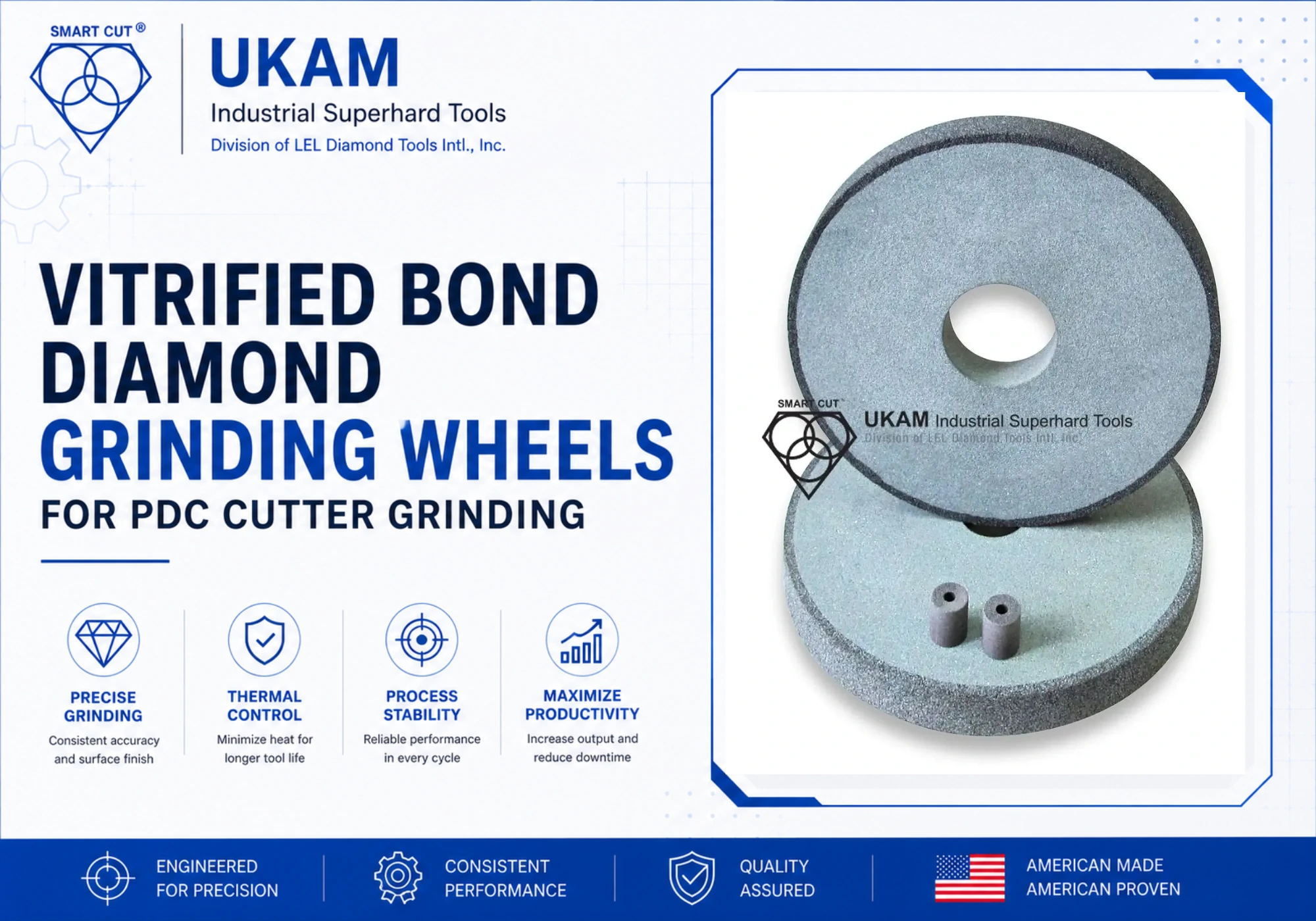
Table of Contents
Toggle
American Based Manufacturer

Established in 1990


Custom manufacturing


Engineering Principles, Process Optimization & Troubleshooting Guide
For engineers, process managers, and applications teams working with PDC cutters in oil & gas, mining, and geothermal drilling
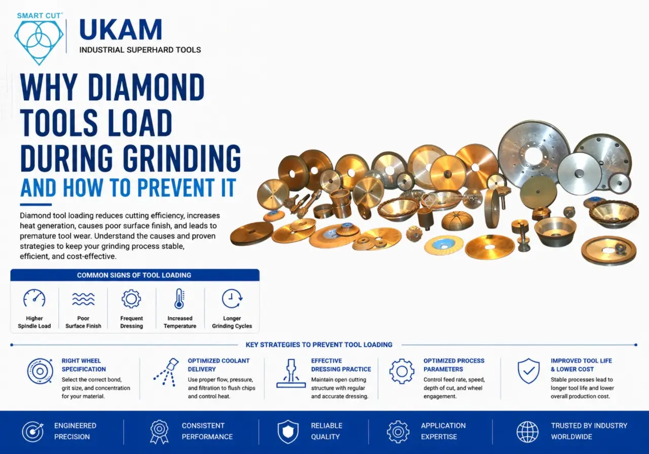
PDC cutter grinding fails in three specific ways: thermal damage to the diamond layer, chipping at the diamond-carbide interface, and wheel glazing that stops material removal entirely. Each failure mode has a distinct cause and a distinct fix. Most process problems trace back to one of three decisions: the wrong bond system, inadequate coolant delivery, or unchanged parameters across the diamond-carbide transition zone.
This guide addresses all three. It covers the material science behind PDC grinding difficulty, why vitrified bond outperforms alternative systems, how to set starting parameters, how to manage the transition zone, and what wheel specification variables actually control surface finish and tool life.
What Makes PDC Cutters Difficult to Grind
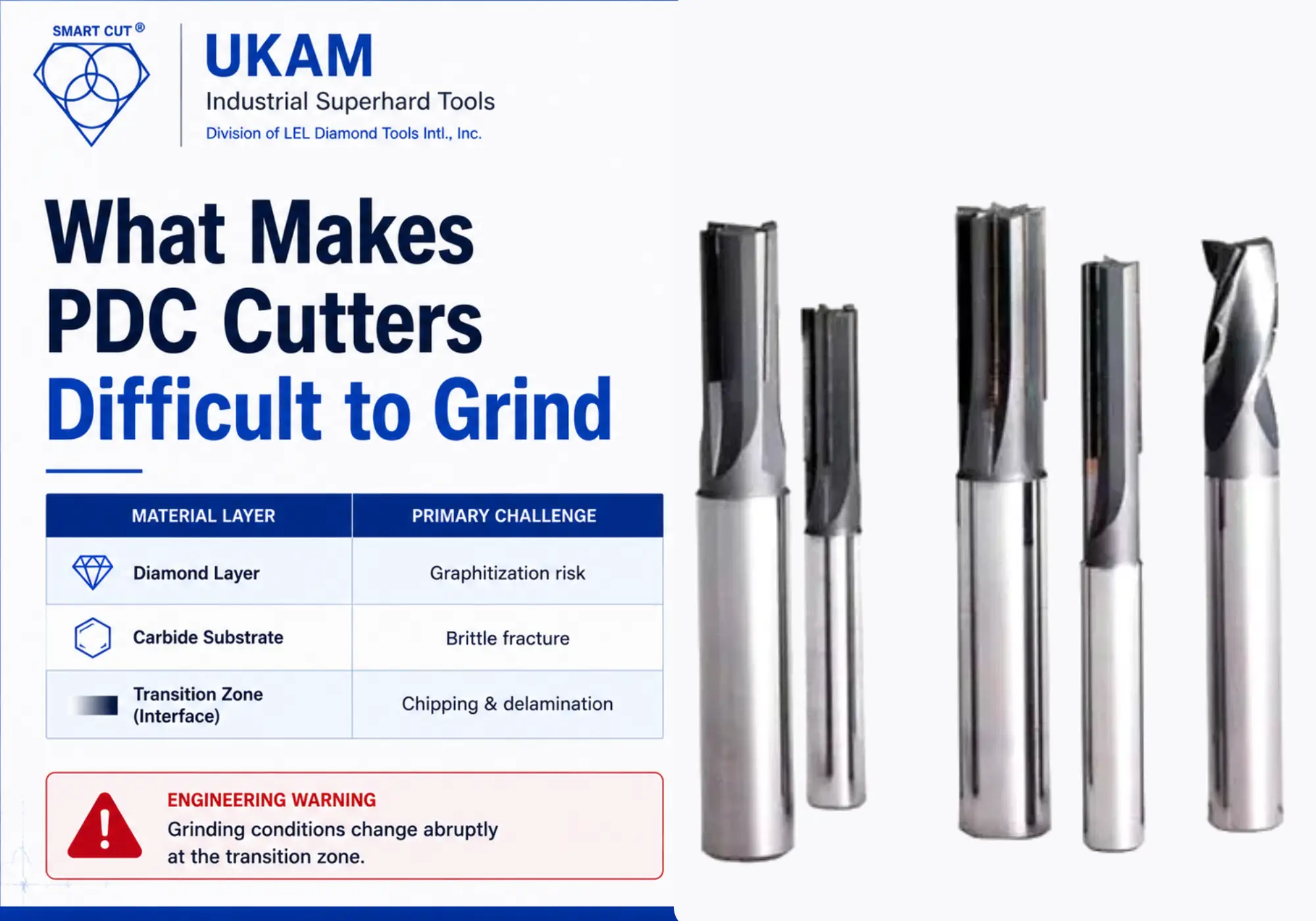
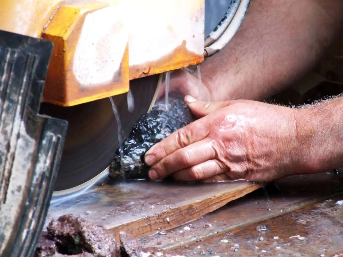
PDC cutters are manufactured by sintering polycrystalline diamond particles onto a cemented tungsten carbide substrate under pressures exceeding 5 GPa and temperatures above 1,400°C. The result is a bi-layer structure combining two materials with fundamentally different mechanical and thermal properties.
|
Material Layer |
Hardness (HV |
Thermal Conductivity |
Fracture Toughness |
Primary Challenge |
|---|---|---|---|---|
|
Polycrystalline Diamond Layer |
6,000 to 10,000 |
500 to 2,000 W/mK |
6 to 10 MPa·m½ |
Diamond-on-diamond interaction, graphitization risk above 700°C |
|
Tungsten Carbide Substrate |
1,300 to 1,800 |
80 to 100 W/mK |
10 to 15 MPa·m½ |
Brittle fracture at high grinding forces |
|
Transition Zone (Interface) |
Gradient |
Gradient |
Lowest in structure |
Delamination, chipping, thermal shock cracking |
The grinding wheel does not encounter a uniform material. At the transition zone, hardness, thermal conductivity, elastic modulus, and fracture toughness all change abruptly within fractions of a millimeter. Feed rates and depths of cut that work on carbide will cause chipping and cracking at the interface.
TECHNICAL NOTE
PDC grinding involves diamond-on-diamond interaction. The specific grinding energy is several times higher than carbide grinding. Wheels that perform well on carbide will glaze rapidly on PDC if the bond system, concentration, and dressing interval are not matched to the application
Material Removal Mechanisms in PDC Grinding
Material removal in PDC grinding is not simple abrasive cutting. At least five simultaneous mechanisms are active during grinding, and their relative contribution shifts depending on wheel speed, depth of cut, and coolant delivery.
|
Mechanism |
Dominant Condition |
Primary Risk if Uncontrolled |
|---|---|---|
|
Mechanical micro-fracture |
Sharp diamond grits, low thermal load |
Subsurface crack propagation |
|
Intergranular fracture |
Coarse grit, high feed rate |
Surface roughness, edge pullout |
|
Transgranular fracture |
Fine grit, high wheel speed |
Deeper subsurface damage |
|
Thermochemical oxidation |
Temperature above 600°C in air |
Diamond graphitization, permanent hardness loss |
|
Micro-plastic deformation |
High pressure at abrasive tip |
Wheel glazing, rising grinding force |
WARNING
PDC diamond begins graphitization at approximately 700°C in oxidizing environments. Thermal damage is typically subsurface and will not appear during visual inspection. Post-process inspection for critical applications should include surface profilometry, microscopic inspection, and hardness testing.
The Three Primary PDC Grinding Failure Modes
1. Wheel Glazing and Rising Grinding Resistance
Wheel glazing occurs when abrasive grains dull but remain embedded in the bond matrix rather than fracturing away. The wheel continues to rotate but loses cutting action. Spindle load climbs, grinding temperatures rise, and surface quality deteriorates rapidly.
|
Symptom |
Most Likely Cause |
Corrective Action |
|---|---|---|
|
Rising spindle load |
Bond hardness too high for material |
Specify softer bond grad |
|
Surface burning |
Wheel glazing combined with poor coolant |
Dress wheel, improve coolant delivery |
|
Poor material removal rate |
Diamond concentration too low |
Increase concentration to 100 to 125% |
|
Elevated grinding temperature |
Inadequate coolant penetration |
Increase coolant pressure to minimum 40 bar |
|
Rapid wheel wear after dressing |
Incorrect diamond friability |
Specify tougher crystal grade |
2. Thermal Damage to the Diamond Layer
Thermal damage is the highest-consequence failure mode in PDC grinding because it is often invisible at the surface. Internal graphitization, subsurface micro-cracking, and localized hardness loss can be present while surface Ra measurements appear acceptable.
|
Sign of Thermal Damage |
Inspection Method |
When to Perform |
|---|---|---|
|
Surface discoloration or hazy appearance |
Visual and optical microscopy |
After every new parameter trial |
|
Subsurface micro-cracks |
Cross-section metallography |
When surface discoloration is detected |
|
Reduced cutter life in service |
Field performance tracking |
Ongoing production monitoring |
|
Surface softening |
Micro-hardness testing (Vickers) |
When thermal indicators are present |
3. Chipping at the Diamond-Carbide Interface
The transition zone between the diamond layer and the carbide substrate has the lowest fracture toughness in the entire cutter structure. Feed rate, depth of cut, and wheel imbalance all contribute to chipping and delamination at this zone. The single most effective corrective action is reducing feed rate by 50 to 70% before reaching the interface.
|
Problem at Interface |
Primary Cause |
Corrective Action |
|---|---|---|
|
Edge chipping |
Excessive feed rate at transition |
Reduce feed by 50 to 70% before interface |
|
Delamination |
Thermal shock from poor coolant |
Increase coolant flow at interface |
|
Transition cracking |
Wheel imbalance |
Balance to G2.5 minimum, G1.0 for precision |
|
Perimeter fracture |
Depth of cut too aggressive |
Reduce depth of cut to 0.001 to 0.003 mm at interface |
Why Vitrified Bond Diamond Wheels Are the Preferred Choice for PDC Grinding
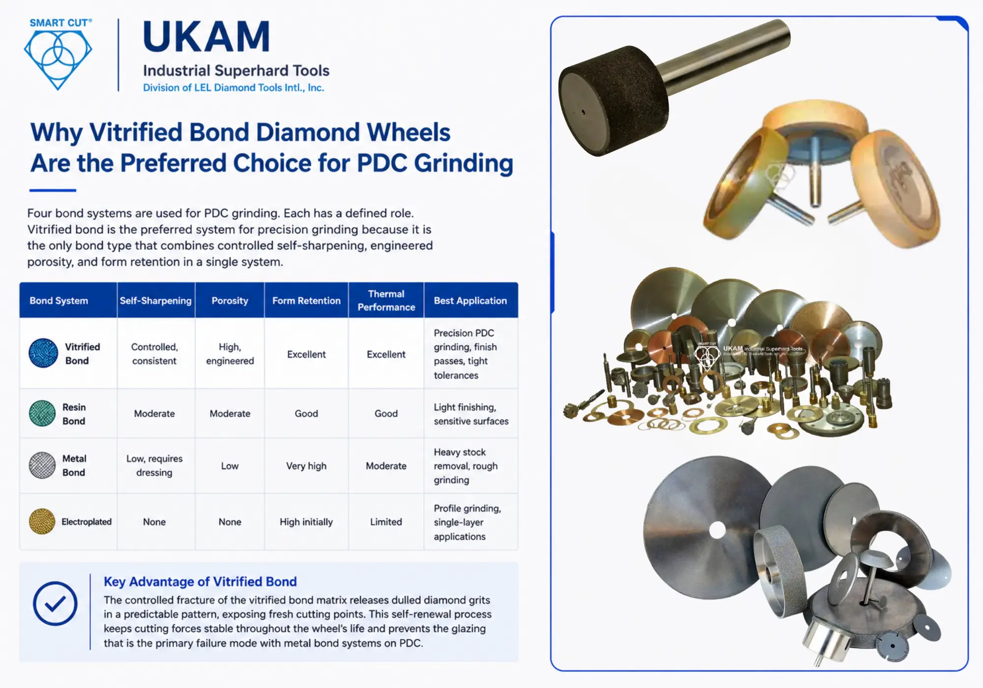
Four bond systems are used for PDC grinding. Each has a defined role. Vitrified bond is the preferred system for precision grinding because it is the only bond type that combines controlled self-sharpening, engineered porosity, and form retention in a single system.
|
Bond System |
Self-Sharpening |
Porosity |
Form Retention |
Thermal Performance |
Best Application |
|---|---|---|---|---|---|
|
Controlled, consistent |
High, engineered |
Excellent |
Excellent |
Precision PDC grinding, finish passes, tight tolerances |
|
|
Moderate |
Moderate |
Good |
Good |
Light finishing, sensitive surfaces |
|
|
Low, requires dressing |
Low |
Very high |
Moderate |
Heavy stock removal, rough grinding |
|
|
None |
None |
High initially |
Limited |
Profile grinding, single-layer applications |
The critical advantage of vitrified bond in PDC applications is the controlled fracture mechanism. Under grinding pressure, the vitrified bond matrix fractures in a predictable pattern, releasing dulled diamond grits and exposing fresh cutting points. This self-renewal process keeps cutting forces stable throughout the wheel’s life and prevents the glazing that is the primary failure mode with metal bond systems on PDC.
TECHNICAL NOTE
The engineered porosity in vitrified bond wheels serves two functions simultaneously. The pore network transports coolant directly to the grinding interface, and it provides pathways for chip evacuation. In PDC grinding, where thermal load is the primary damage risk, this architecture is a process variable, not simply a design feature.
Wheel Specification Variables That Control Performance
Grit size and bond type are the two variables most engineers specify first. They are not the most important. Diamond crystal type, friability, concentration, porosity percentage, and bond hardness grade have a larger combined effect on grinding performance than grit size selection alone.
Diamond Crystal Type and Friability
Diamond crystals for grinding wheels are manufactured with varying friability ratings. A high-friability crystal fractures under lower force, continuously exposing sharp micro-edges. A low-friability crystal is tougher and resists fracture, retaining its shape longer under load.
|
Crystal Type |
Friability |
Best Use in PDC Grinding |
Risk if Misspecified |
|---|---|---|---|
|
Blocky, low friability |
Low |
Heavy stock removal, rough grinding passes |
Wheel glazing in finish grinding, rising forces |
|
Intermediate friability |
Medium |
General purpose PDC grinding, most production environments |
Limited risk, most forgiving specification |
|
High friability (sharp, irregular) |
High |
Finish grinding, low-force applications, thermally sensitive passes |
Rapid wheel wear in aggressive roughing |
Diamond Concentration
Diamond concentration is expressed as a percentage, where 100% concentration equals 4.4 carats per cubic centimeter of wheel volume. Higher concentration provides more cutting points per unit area. Lower concentration allows individual grits to carry higher load, promoting controlled fracture and self-sharpening.
|
Concentration |
Cutting Points per cm² |
Grinding Force per Grit |
Recommended Application |
|---|---|---|---|
|
75% |
Lower |
Higher per grit, faster self-sharpening |
Soft bond grades, finish passes, thermal-sensitive materials |
|
100% |
Moderate |
Balanced |
General PDC grinding, most production environments |
|
125% |
Higher |
Lower per grit, longer life before dressing |
High-volume roughing, abrasive materials, long runs |
|
150 to 200% |
Very high |
Very low per grit |
Aggressive stock removal, rough grinding only |
Bond Hardness Grade
|
Bond Grade |
Grit Retention |
Self-Sharpening Rate |
Recommended Condition |
|---|---|---|---|
|
Soft (J to K) |
Low |
High |
Hard materials like PDC diamond layer, materials that dull grits quickly |
|
Medium (L to M) |
Moderate |
Moderate |
General PDC grinding, carbide substrate grinding |
|
Hard (N to P) |
High |
Low |
Soft materials, high-speed grinding, long production runs on carbide |
Bond hardness grade controls how readily the bond matrix releases worn diamond grits. A soft grade releases grits early, maintaining sharpness but reducing wheel life. A hard grade retains grits longer, extending wheel life but increasing glazing risk if the balance between grit wear and bond release is off.
Porosity Percentage
Porosity in vitrified bond wheels is controlled during manufacturing and directly affects coolant transport and chip evacuation. Standard porosity is approximately 30 to 40% of wheel volume. Open-structure wheels with 45 to 55% porosity are specified for PDC grinding applications where thermal management is the primary concern.
ENGINEERING PRINCIPLE
Specifying porosity percentage is as important as specifying grit size for PDC grinding. A wheel with identical grit and concentration but 15% lower porosity will run significantly hotter at the same parameters. Always confirm the porosity specification with the manufacturer when ordering for thermal-sensitive applications.
Recommended Grinding Parameters for PDC Cutters
The following values are validated starting points for production environments. Actual parameters depend on machine rigidity, cutter geometry, coolant system capability, and material removal requirements. Do not transfer these values between machines without a parameter validation run.
|
Parameter |
Rough Grinding |
Semi-Finish Grinding |
Finish Grinding |
|---|---|---|---|
|
Diamond Grit Size |
80 to 150 mesh |
150 to 270 mes |
270 to 400 mesh |
|
Wheel Speed |
20 to 30 m/s |
18 to 25 m/s |
18 to 22 m/s |
|
Depth of Cut |
0.010 to 0.020 mm |
0.005 to 0.010 mm |
0.001 to 0.005 mm |
|
Feed Rate |
Standard |
Reduce 30% from rough |
Reduce 60% from rough |
|
Diamond Concentration |
125 to 200% |
100 to 125% |
100 to 125% |
|
Coolant Pressure |
40 bar minimum |
40 bar minimum |
40 bar minimum |
|
Coolant Type |
Water-based EP coolant |
Water-based syntheti |
Synthetic high-pressure |
|
Dress Interval |
Every 20 to 40 parts |
Every 15 to 25 parts |
Every 10 to 20 parts |
WARNING
Never exceed the wheel manufacturer’s maximum RPM specification. At high spindle speeds, even minor wheel imbalance amplifies significantly. Balance all wheels to G2.5 minimum before use. For ultra-precision applications, balance to G1.0 or better.
Grinding the Diamond-Carbide Transition Zone
The transition zone is the section of the grind where the wheel crosses from the tungsten carbide substrate into the polycrystalline diamond layer. This crossing is the highest-risk step in PDC grinding. Parameters that are acceptable for carbide will cause chipping, delamination, and thermal cracking if maintained unchanged into the diamond layer.
Multi-Stage Grinding Strategy
|
Stage |
Parameters |
Wheel Condition Required |
Key Monitoring Poin |
|---|---|---|---|
|
Stage 1: Carbide Grinding |
Standard feed rate, moderate depth of cut, coarser grit wheel |
Normal condition, regular dress schedule |
Spindle load stability |
|
Stage 2: Approaching the Interface (0.1 to 0.5 mm before) |
Reduce feed rate by 50 to 70%, reduce depth of cut significantly |
Freshly dressed wheel, confirmed balance |
Any change in spindle load indicates interface crossing |
|
Stage 3: Diamond Layer Entry |
Maintain reduced feed and depth from Stage 2, do not increase |
Stable coolant flow, vibration minimized |
Thermal indicator monitoring, edge chipping inspection |
|
Stage 4: Full Diamond Laye |
Low thermal input, consistent cutting action |
Dress interval tightened vs. carbide grinding |
Surface finish consistency, spindle load stability |
TECHNICAL NOTE
A sudden change in spindle load during grinding is the most reliable real-time indicator that the wheel has reached the transition zone. Some machines can be programmed to trigger an automatic feed rate reduction at a defined spindle load threshold. This is the most reliable method for protecting the interface on high-volume production lines
Coolant Requirements for PDC Grinding
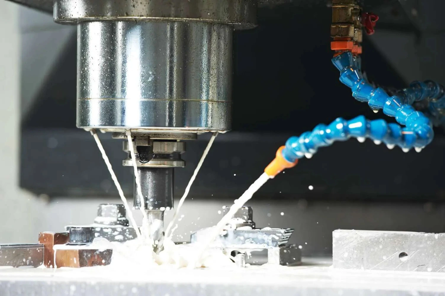
Coolant in PDC grinding is a critical process variable, not a supporting element. At operating wheel speeds, a high-velocity air barrier forms around the wheel and actively prevents coolant from reaching the grinding interface. Standard flood coolant systems are insufficient for PDC applications.
|
Requirement |
Specification |
Consequence if Not Me |
|---|---|---|
|
Delivery method |
High-pressure coherent jet system |
Air barrier prevents coolant from reaching interface |
|
Minimum pressure |
40 bar at the nozzle |
Thermal damage, graphitization risk above 700°C |
|
Nozzle position |
Directed at contact-zone entry point |
Coolant misses the grinding interface entirely |
|
Coolant type |
Water-based synthetic with EP additives |
Inadequate lubrication, accelerated wheel wear |
|
Filtration |
Fine particulate filtration |
Abrasive swarf recirculates and damages wheel and workpiece |
|
Temperature control |
Stable coolant temperature |
Thermal expansion affects dimensional tolerance at tight specs |
|
Coolant concentration |
Maintained within manufacturer specification |
Reduced lubrication and corrosion protection |
ENGINEERING PRINCIPLE
Incorrect nozzle positioning is one of the most common and least diagnosed causes of thermal damage in PDC grinding. The nozzle must be aimed at the entry point of the grinding contact zone, not at the wheel surface above or beside the contact area. Confirm nozzle position visually before each production run
Surface Finish Targets by Application
|
Application |
Target Ra |
Grit Sequence |
Special Requirement |
|---|---|---|---|
|
Standard oil & gas PDC (drilling service) |
0.4 to 0.8 µm |
270 to 400 mesh finish pass |
Edge integrity at transition zone is primary criterion |
|
Premium PDC cutters (directional drilling) |
0.1 to 0.4 µm |
400 to 600 mesh plus polishing |
Subsurface damage inspection required |
|
Geothermal applications (high-temp service) |
0.05 to 0.1 µm |
ELID grinding sequence |
Thermal stability of surface layer must be verified |
|
Metrology and research |
Below 0.02 µm |
Nano-abrasive polishing |
SEM inspection of final surface recommended |
Cost-Per-Part Analysis: Vitrified Bond vs. Metal Bond
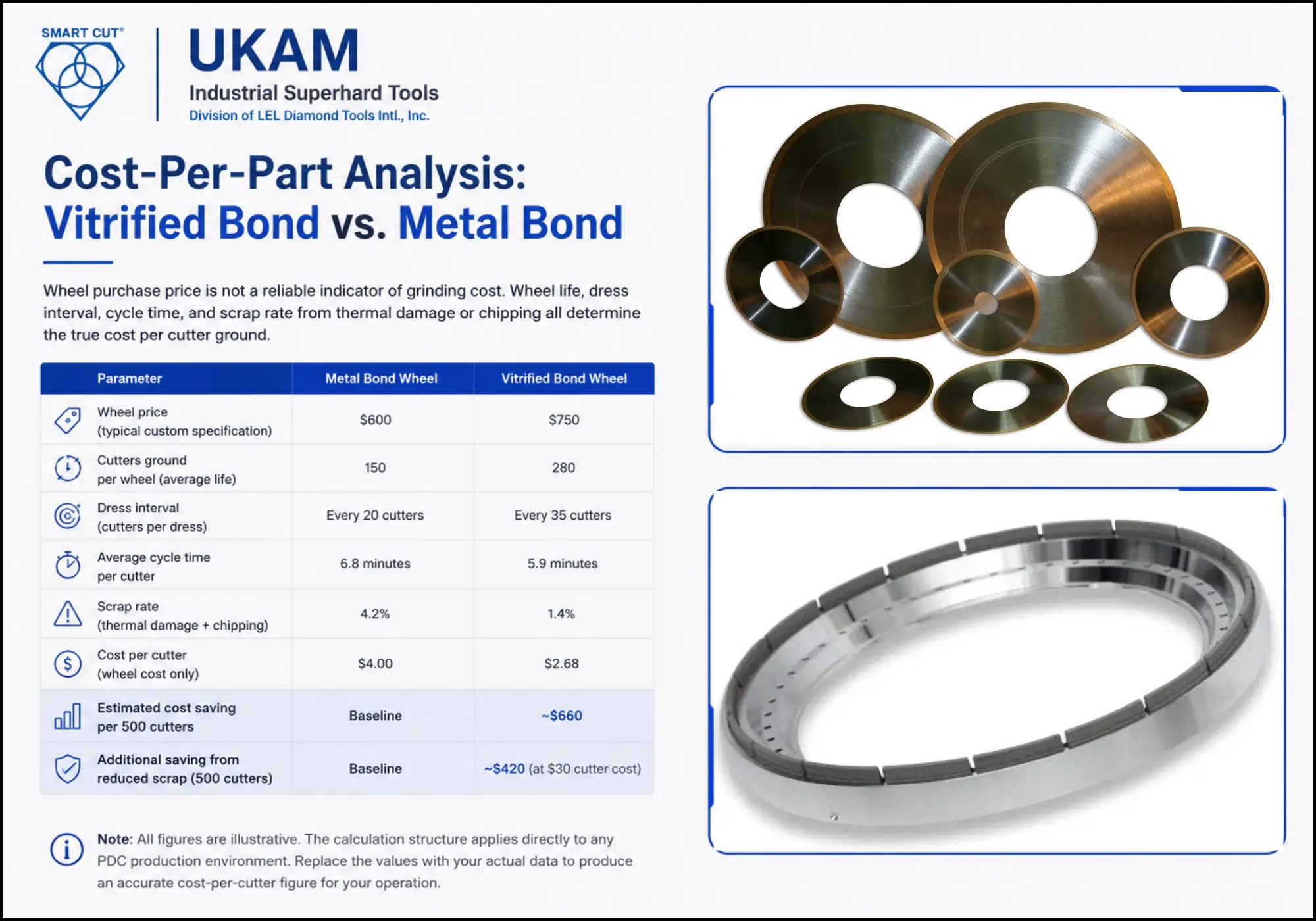
Wheel purchase price is not a reliable indicator of grinding cost. Wheel life, dress interval, cycle time, and scrap rate from thermal damage or chipping all determine the true cost per cutter ground. The following comparison uses illustrative figures based on typical PDC production environments. Actual results depend on material grade, machine parameters, and cutter geometry.
|
Parameter |
Metal Bond Wheel |
Vitrified Bond Wheel |
|---|---|---|
|
Wheel price (typical custom specification) |
$600 |
$750 |
|
Cutters ground per wheel (average life) |
150 |
280 |
|
Dress interval (cutters per dress) |
Every 20 cutters |
Every 35 cutters |
|
Average cycle time per cutter |
6.8 minutes |
5.9 minutes |
|
Scrap rate (thermal damage + chipping) |
4.2% |
1.4% |
|
Cost per cutter (wheel cost only) |
$4.00 |
$2.68 |
|
Estimated cost saving per 500 cutters |
Baseline |
~$660 |
|
Additional saving from reduced scrap (500 cutters) |
Baseline |
~$420 (at $30 cutter cost) |
Note: All figures are illustrative. The calculation structure applies directly to any PDC production environment. Replace the values with your actual wheel price, measured wheel life, dress interval, and scrap rate to produce an accurate cost-per-cutter figure for your operation.
ENGINEERING PRINCIPLE
In most PDC grinding environments, vitrified bond wheels deliver a lower cost per cutter than metal bond wheels despite a higher purchase price. The performance difference compounds across wheel life: longer life, fewer dress cycles, shorter cycle time, and lower scrap rate all reduce cost simultaneously.
Process Improvement Example: Bond System Transition
The following example illustrates the performance differences engineers typically observe when transitioning from metal bond to vitrified bond diamond wheels for PDC cutter grinding. These figures are representative of results documented in production qualification trials. Actual outcomes vary by cutter grade, machine configuration, and starting parameters.
|
Performance Variable |
Metal Bond (Before) |
Vitrified Bond (After) |
Change |
|---|---|---|---|
|
Surface finish Ra (finish pass |
0.55 to 0.70 µm |
0.18 to 0.28 µm |
60% improvement |
|
Grinding forces (average normal force) |
Baseline |
32% lower |
Reduced thermal load and subsurface damage risk |
|
Dress interval |
Every 18 to 22 cutters |
Every 30 to 40 cutters |
75% longer between dresses |
|
Interface chipping rate |
8 to 12% of cutters |
1 to 3% of cutters |
80% reduction |
|
Thermal damage incidents |
Occasional (process-dependent) |
Rare (with correct coolant setup) |
Significant reduction |
|
Cycle time per cutter |
Baseline |
12% shorter |
Faster cutting action, less glazing |
TECHNICAL NOTE
The interface chipping rate improvement is the variable with the highest impact on cutter yield. A reduction from 10% to 2% on a 500-cutter production run eliminates 40 scrapped cutters per run. At a typical cutter cost, that single variable often justifies the bond system transition on its own.
Wheel Dressing Best Practices
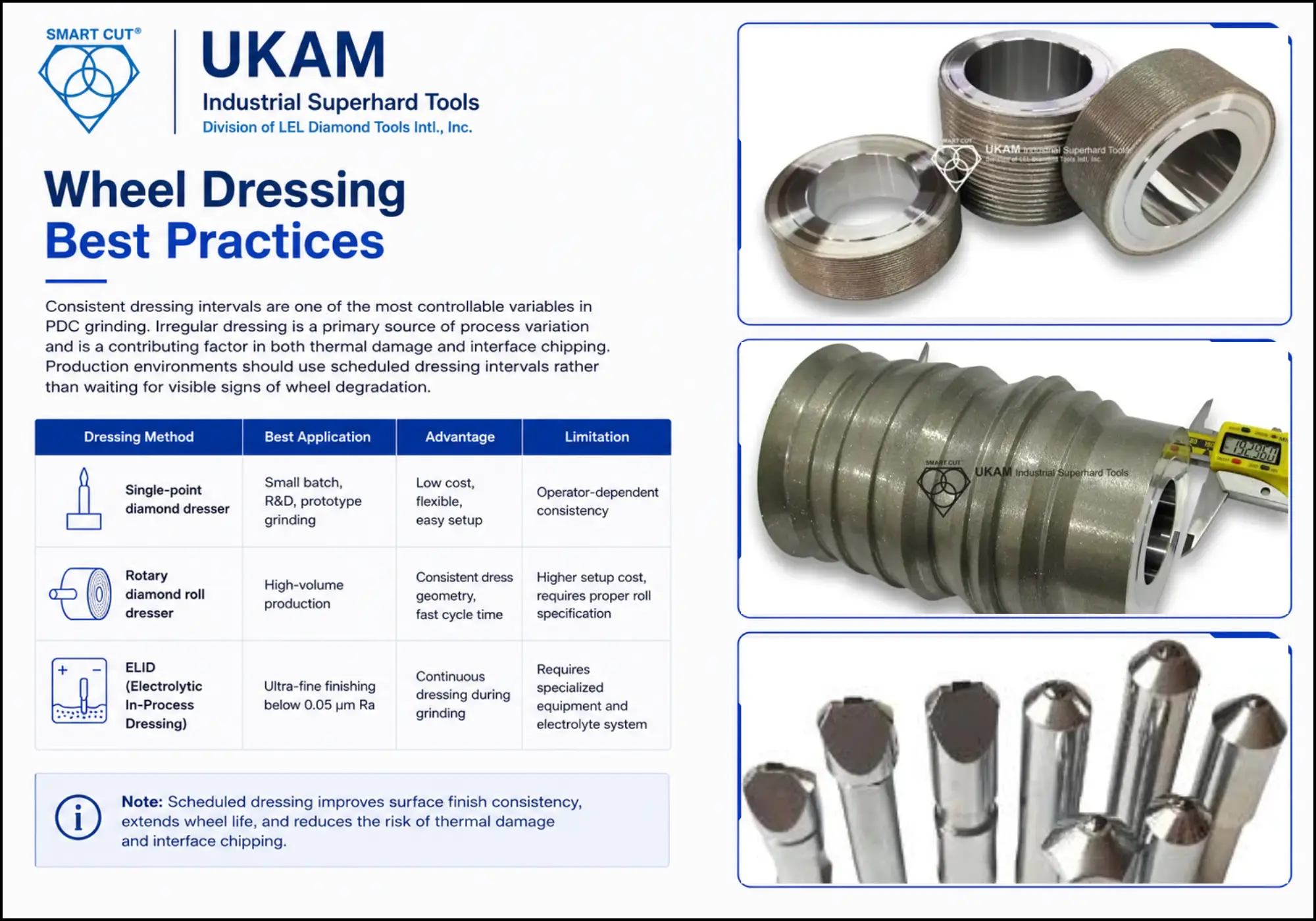
Consistent dressing intervals are one of the most controllable variables in PDC grinding. Irregular dressing is a primary source of process variation and is a contributing factor in both thermal damage and interface chipping. Production environments should use scheduled dressing intervals rather than waiting for visible signs of wheel degradation.
|
Dressing Method |
Best Application |
Advantag |
Limitation |
|---|---|---|---|
|
Small batch, R&D, prototype grinding |
Low cost, flexible, easy setup |
Operator-dependent consistency |
|
|
High-volume production |
Consistent dress geometry, fast cycle time |
Higher setup cost, requires proper roll specification |
|
|
ELID (Electrolytic In-Process Dressing |
Ultra-fine finishing below 0.05 µm Ra |
Continuous dressing during grinding |
Requires specialized equipment and electrolyte system |
|
Sign That Dressing Is Required |
Likely Cause |
Action |
|---|---|---|
|
Rising grinding forces |
Grit dulling, bond loading |
Dress immediately, check concentration spec |
|
Surface finish deterioration |
Wheel glazing beginning |
Dress and reduce dress interval for next run |
|
Wheel loading (visible) |
Chip packing in pores |
Dress and verify coolant flow and filtration |
|
Increased vibration |
Wheel imbalance or loading |
Dress and rebalance if vibration persists |
|
Burn marks on cutter surface |
Thermal damage in progress |
Stop, dress immediately, check coolant delivery |
Evaluating a Vitrified Bond Diamond Wheel Supplier
Not all vitrified bond diamond wheels are equivalent. Bond matrix formulation, diamond crystal selection, porosity control, and manufacturing consistency all vary between suppliers. A supplier who quotes immediately from a standard catalog is selling a commodity specification. A supplier who asks about your cutter grade, machine parameters, and surface finish requirements before quoting is providing application engineering.
|
What to Ask |
What the Answer Reveals |
|---|---|
|
Do you ask about cutter grade and hardness before specifying grit size? |
Whether they understand that PDC hardness varies and affects wheel specification |
|
Can you specify porosity percentage, not just bond type? |
Whether they control porosity as a manufacturing variable or simply classify by bond label |
|
What diamond crystal type and friability grade do you recommend for this application, and why? |
Depth of application knowledge vs. catalog selection |
|
Do you manufacture in-house or source wheels from a third party? |
Whether they can modify specifications, control quality, and support custom orders |
|
Can you provide a starting parameter recommendation based on our machine and cutter geometry? |
Whether they support process integration or only sell wheels |
|
What is your lead time on a custom specification with non-standard porosity or concentration? |
Manufacturing capability and flexibility for production planning |
|
Do you have documented experience with PDC cutter grinding specifically? |
Reduces qualification risk substantially vs. a general abrasives supplier |
UKAM Industrial Superhard Tools: Manufacturing Capability
UKAM has manufactured precision diamond and CBN grinding wheels since 1990. The following comparison reflects UKAM’s manufacturing specifications relative to standard catalog-grade vitrified bond wheels available from general abrasives distributors.
UKAM has manufactured precision diamond and CBN grinding wheels since 1990. The following comparison reflects UKAM’s manufacturing specifications relative to standard catalog-grade vitrified bond wheels available from general abrasives distributors.
|
Specification Variable |
Standard Catalog Wheel |
UKAM Custom Vitrified Bond |
|---|---|---|
|
Diamond crystal selection |
Single standard grade |
Application-matched crystal type and friability |
|
Concentration range available |
100% standard |
75% to 200%, specified per application |
|
Porosity control |
Standard open or closed structure |
Engineered porosity percentage specified at order |
|
Bond hardness grades |
Limited range (L to N typical) |
Full range available including soft grades for PDC diamond layer |
|
Custom OD/ID/face geometry |
Standard catalog dimensions only |
Full custom geometry available |
|
Application engineering support |
Catalog reference |
Starting parameters, trial support, specification adjustment |
|
Lead time (custom specification) |
6 to 10 weeks typical |
2 to 4 weeks for repeat specifications |
|
Minimum order quantity |
Often high for custom specs |
Small batch available for R&D and qualification |
UKAM manufactures vitrified bond diamond wheels for PDC cutter grinding, advanced ceramics, sapphire, tungsten carbide, semiconductor materials, precision optics, and glass applications. Custom specifications are available for non-standard geometries, specialized bond formulations, and high-precision production environments.
Complete Troubleshooting Reference
|
Problem |
Probable Cause |
Corrective Action |
Prevention |
|---|---|---|---|
|
Wheel glazing |
Bond too hard, concentration too low |
Specify softer bond grade, increase dress frequency |
Match bond grade to cutter hardness at specification stage |
|
Thermal cracking (cutter surface) |
Poor coolant delivery, glazed wheel |
Improve coolant pressure and nozzle position, dress wheel |
Verify coolant setup before every production run |
|
Interface chipping |
Excessive feed rate at transition zone |
Reduce feed by 50 to 70% before interface |
Program feed rate change at defined spindle load threshold |
|
Chatter marks |
Wheel imbalance |
Rebalance to G2.5 or G1.0 |
Balance check before every wheel installation |
|
Rapid wheel wear |
Incorrect diamond grade (too friable) |
Specify tougher crystal grade |
Confirm crystal friability for application before ordering |
|
Poor edge sharpness |
Wheel loading, dress interval too long |
Dress more frequently, verify coolant filtration |
Schedule dress intervals, do not wait for visible degradation |
|
Subsurface micro-cracking |
Excessive depth of cut or grinding force |
Reduce depth of cut, verify wheel balance |
Use cross-section inspection after parameter changes |
|
Inconsistent surface finish lot to lot |
Irregular dress interval or coolant concentration |
Standardize dress interval, check coolant concentration |
Use scheduled dressing, document and monitor coolant concentration |
Frequently Asked Questions
Grit selection depends on the stage of grinding and the required surface finish. For rough grinding and bulk stock removal, 80 to 150 mesh is the standard range. Semi-finishing passes use 150 to 270 mesh. Finish grinding targeting Ra values of 0.1 to 0.4 µm uses 270 to 400 mesh. Ultra-fine finishing below 0.05 µm Ra requires 600 mesh or finer, typically in an ELID grinding sequence. The correct grit for any specific application also depends on machine rigidity, cutter hardness grade, and coolant system capability. A wheel with the correct grit but an oversized depth of cut will produce worse surface finish than a coarser wheel at the correct parameters.
Glazing is caused by a mismatch between the bond’s grit release rate and the grinding conditions. The four most common causes are bond hardness too high for the cutter material, diamond concentration too high (individual grits carry insufficient load to promote fracture and renewal), inadequate coolant penetration that increases surface temperature and softens the bond, and dress intervals that are too long. The corrective action depends on which cause is dominant. If glazing occurs immediately after dressing, the specification is wrong. If glazing develops gradually over a production run, the dress interval needs shortening. If glazing only occurs at higher feed rates, the bond grade is too hard for the application.
PDC grinding requires a high-pressure coherent jet coolant system delivering a minimum of 40 bar at the nozzle, directed at the entry point of the grinding contact zone. Standard flood coolant is insufficient because at operating wheel speeds, the rotating wheel generates a high-velocity air barrier that deflects flood coolant away from the interface. Water-based synthetic coolant with extreme-pressure additives is the standard specification. Straight oil is not recommended for vitrified bond systems. Coolant concentration must be maintained within the manufacturer’s specification throughout the production run. Fine particulate filtration is required to prevent abrasive swarf from recirculating and damaging both the wheel surface and the cutter.
Chipping at the interface has four primary causes. Excessive feed rate is the most common: parameters set for carbide grinding are maintained unchanged into the diamond layer, where the lower fracture toughness cannot absorb the same grinding force. Wheel imbalance is the second most common cause and is also the most overlooked. Even minor imbalance amplifies significantly at high spindle speeds and creates impact loading at the interface. Thermal shock from inadequate coolant delivery is the third cause, and it is often misdiagnosed as a wheel specification problem. Excessive depth of cut is the fourth. Reducing feed rate by 50 to 70% before reaching the interface is the single most effective preventive action and should be standard procedure on every PDC grinding operation.
Technically possible, but not optimal for precision applications. The hardness difference between the carbide substrate and the PDC layer requires different wheel specifications to grind each material at peak efficiency. A wheel optimized for carbide will glaze when it reaches the PDC layer. A wheel optimized for PDC will wear excessively on the carbide substrate. Best practice in production environments uses a multi-stage approach: a coarser, harder wheel for carbide stock removal followed by a softer-bond, finer-grit vitrified wheel for the PDC layer and finish pass. For R&D and low-volume applications where tool changes are impractical, an intermediate specification can be used with parameter changes at the interface, but the performance trade-off should be quantified during the qualification trial.
Production environments should use scheduled dressing intervals rather than reactive dressing triggered by visible degradation. By the time burn marks or surface finish deterioration appear, the wheel has already been operating in a degraded state for multiple parts. Typical starting intervals for PDC grinding are every 20 to 40 parts for rough grinding, every 15 to 25 parts for semi-finishing, and every 10 to 20 parts for finish grinding. These intervals should be verified during the qualification trial by monitoring spindle load, surface finish Ra, and part dimensions at each interval. If quality metrics begin declining before the scheduled dress interval, shorten the interval. If they remain stable well beyond it, the interval can be extended cautiously with monitoring.
G2.5 is the minimum recommended balance grade for standard precision PDC grinding. G1.0 or better is required for ultra-precision applications, tight surface finish specifications, and any application where the transition-zone chipping rate needs to be minimized. At high spindle speeds, even a minor imbalance of a few grams creates a centrifugal force that scales with the square of rotational speed. A wheel balanced to G6.3, which is acceptable for general grinding, can produce measurable chipping and vibration at PDC grinding speeds. Balance all wheels before installation, and rebalance after dressing if the wheel has been dressed unevenly.
Finish grinding PDC cutters requires a high-friability, sharp-edged crystal type. High-friability crystals fracture under lower force, continuously exposing fresh micro-cutting edges and maintaining low grinding forces throughout the wheel’s life. Blocky, low-friability crystals designed for toughness are the correct choice for rough grinding and carbide stock removal, but they produce higher grinding forces in the finish pass and increase the risk of glazing on the hard PDC diamond layer. The crystal type specification should always be confirmed with the manufacturer when ordering finish grinding wheels for PDC applications. Generic catalog descriptions of crystal type are often insufficient for specifying finish grinding performance.
Key Engineering Principles for PDC Grinding
- Thermal damage is the primary failure risk in PDC grinding and is often subsurface. Surface appearance alone is not a sufficient quality check.
- The diamond-carbide transition zone requires a mandatory feed rate reduction of 50 to 70% before the interface. This single action prevents the majority of chipping and delamination failures.
- Vitrified bond is the preferred system for precision PDC grinding because controlled self-sharpening, engineered porosity, and form retention are required simultaneously.
- Diamond crystal friability, concentration, porosity percentage, and bond hardness grade have a larger combined effect on grinding performance than grit size alone.
- High-pressure coherent jet coolant at minimum 40 bar, directed at the contact zone entry point, is a non-negotiable process requirement.
- Scheduled dressing intervals prevent degraded-wheel production. Do not wait for visible surface finish deterioration before dressing.
- Cost per cutter, not wheel purchase price, is the correct metric for evaluating grinding wheel specifications. Longer wheel life, shorter cycle time, and lower scrap rate compound into significant cost advantages that the purchase price comparison does not capture.
- Balance wheels to G2.5 minimum before every installation. For precision applications and transition-zone-sensitive operations, balance to G1.0 or better.
Trusted by Tens of Thousands of Manufacturers, Laboratories,
Research Institutions Worldwide Since 1990
American Based Manufacturer
Established in 1990
Custom manufacturing
RELATED ARTICLES