How Depth of Cut Affects Diamond Blade Life
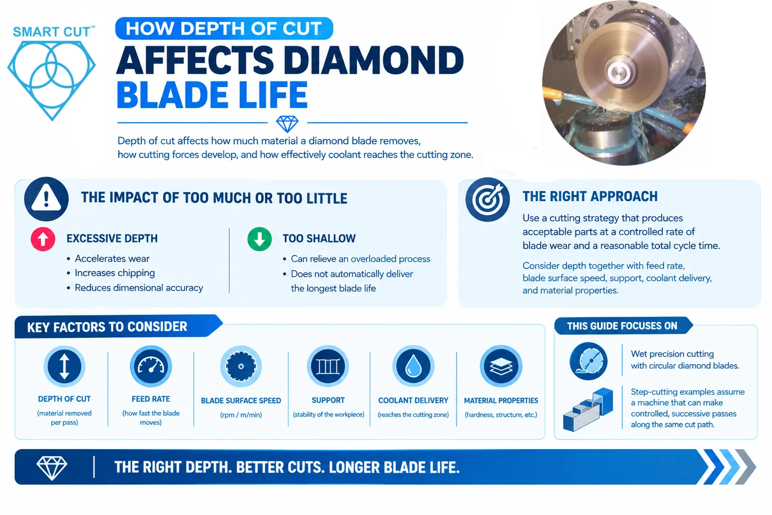
Table of Contents
ToggleDepth of cut affects how much material a diamond blade removes, how cutting forces develop, and how effectively coolant reaches the cutting zone. An excessive depth can accelerate wear, increase chipping, and reduce dimensional accuracy. A smaller depth increment can relieve an overloaded process, but the shallowest possible pass does not automatically deliver the longest blade life.
The useful target is a cutting strategy that produces acceptable parts at a controlled rate of blade wear and a reasonable total cycle time. Reaching that target requires you to consider depth together with feed rate, blade surface speed, support, coolant delivery, and material properties.
This guide focuses on wet precision cutting with circular diamond blades. The step-cutting examples assume a machine that can make controlled, successive passes along the same cut path.
Trusted by Tens of Thousands of Manufacturers, Laboratories Research Institutions Worldwide Since 1990
Established in 1990
Define the depth you are changing
Total penetration is the distance from the original workpiece surface to the lowest cutting point. The depth increment is the additional depth removed during the current pass. In a first pass into a flat surface, those values may be the same. In later passes through an existing groove, they are different.
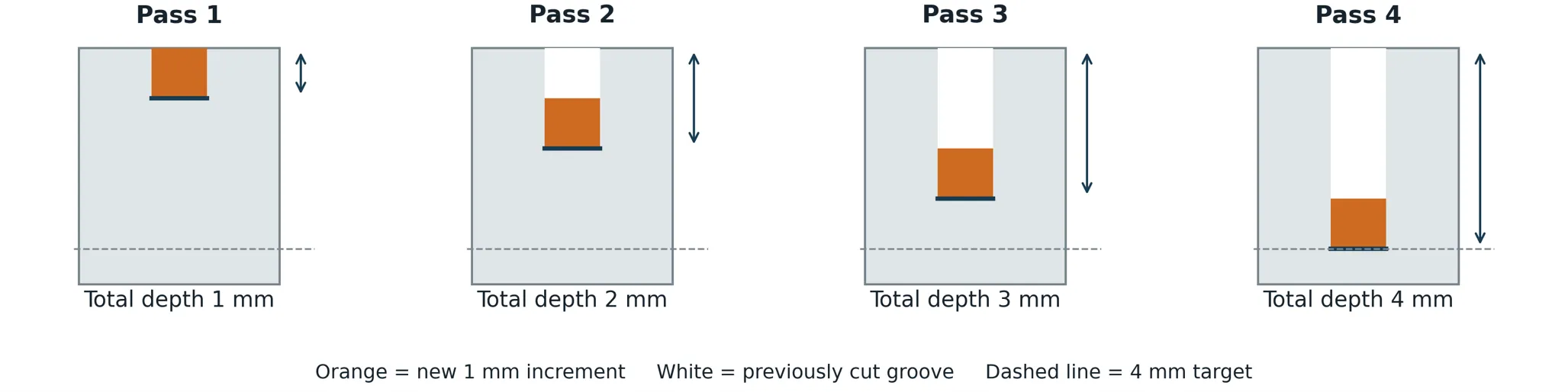
For example, a 4 mm groove made in four equal increments adds 1 mm on each pass. The blade reaches cumulative depths of 1, 2, 3, and 4 mm. On the final pass, it still penetrates 4 mm, even though it removes only the next 1 mm of depth.
This distinction matters because deeper penetration still requires adequate blade exposure, side clearance, and coolant access. Step cutting reduces the new material removed per pass. It does not eliminate the physical depth of the finished groove.
How deeper engagement changes cutting
Contact length and blade diameter
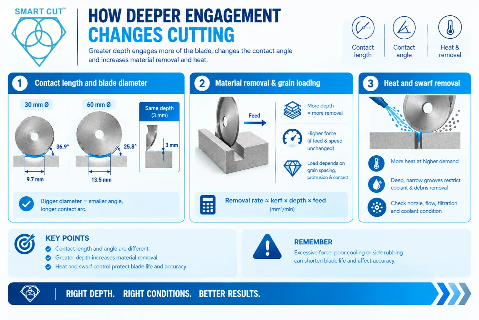
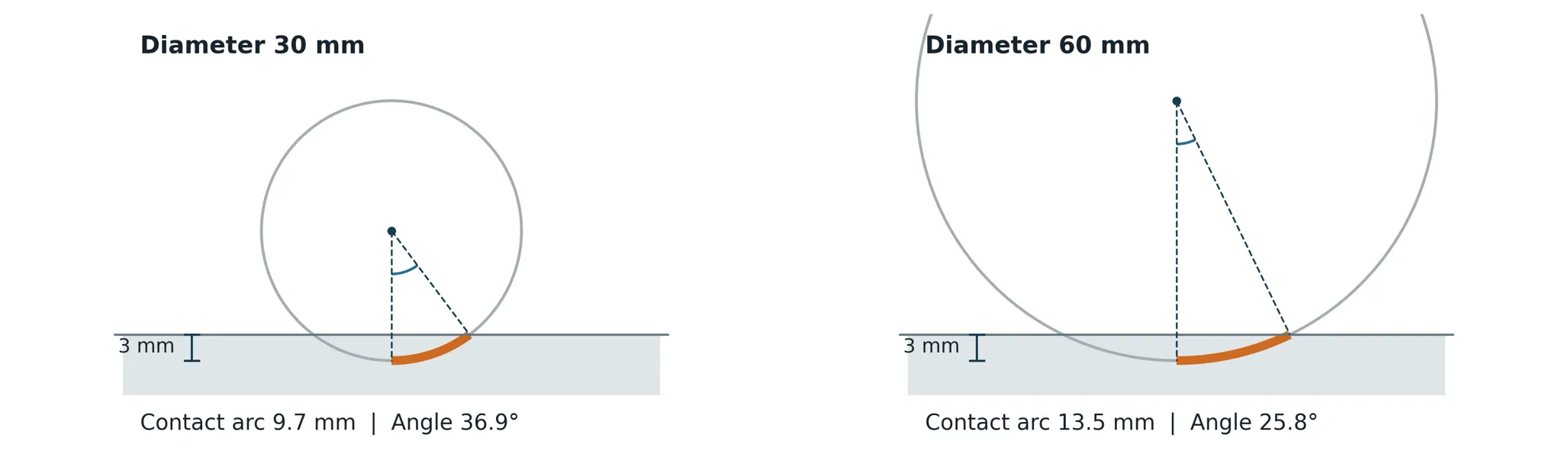
For a first pass into a flat surface, greater penetration engages a longer section of the blade rim. Blade diameter also changes this geometry. At the same penetration, a larger diameter creates a smaller engagement angle but a longer physical contact arc. Contact angle and contact length should therefore be described separately.
These simple relationships change when cutting a round specimen, passing through the bottom of a workpiece, or deepening an existing slot. In step cutting, the rim cutting new material and the blade sides passing through the existing groove perform different roles.
Material removal and grain loading
At unchanged feed rate and kerf width, a larger depth increment removes more material per unit time. If blade surface speed and blade condition also remain unchanged, cutting forces generally increase. The load on individual diamond grains depends on grain spacing, protrusion, contact geometry, and cutting direction. It is not distributed equally among every exposed grain.
For a straight rectangular groove, approximate removal rate equals kerf width multiplied by new depth increment multiplied by feed rate. Using millimeters and millimeters per minute gives cubic millimeters per minute. This calculation describes material removal demand. It does not predict blade life or capture additional side rubbing.
Excessive force can fracture diamonds or release them prematurely from the bond. Inadequate cooling can damage the bond or core. Side rubbing and blade deflection can cause uneven wear and loss of cutting accuracy. These effects can end useful blade life before the available abrasive is fully consumed.
Heat and swarf removal
Higher cutting demand can increase heat generation. A deep, narrow groove can also restrict coolant access and debris removal. Swarf retained in the groove may be recut or rub against the blade, adding friction. Check nozzle position, flow, filtration, and coolant condition. Visible flow above the workpiece does not establish that the lower cutting zone receives enough coolant.
Choose between one pass and step cutting
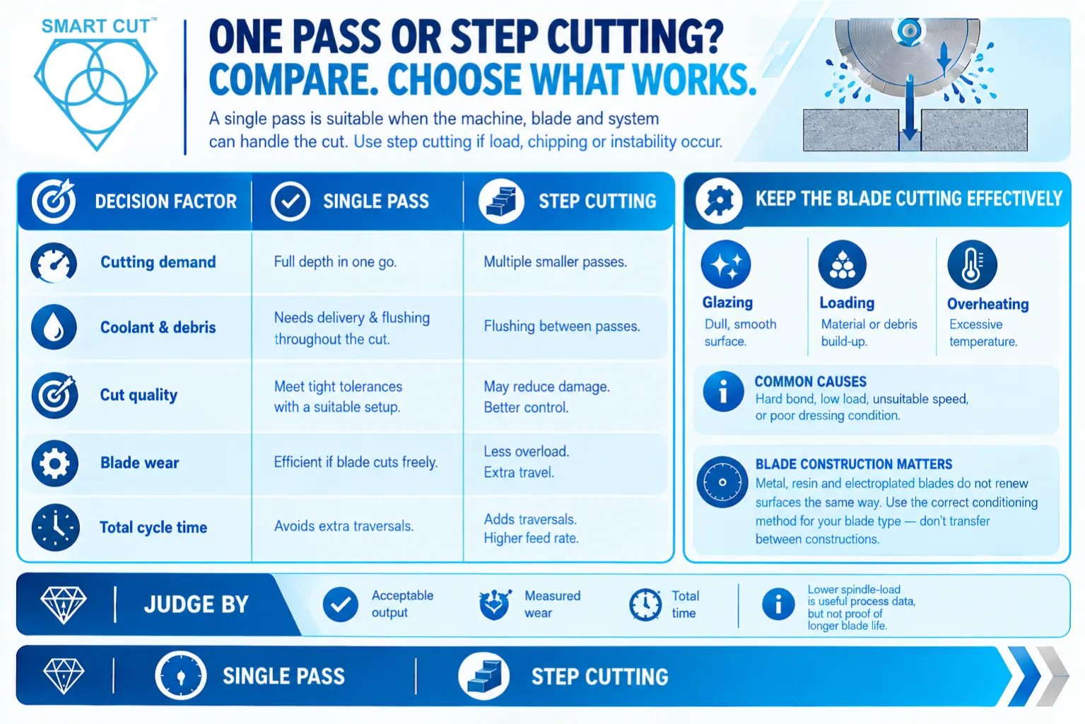
A single pass can be appropriate when the machine, blade, support, and coolant system handle the complete cut without excessive load or unacceptable damage. Step cutting is useful to evaluate when full-depth cutting causes rising load, excessive chipping, or unstable cutting. Compare both strategies over the same completed cut.
| Decision factor | Single pass | Step cutting |
|---|---|---|
| Cutting demand | Removes the required depth in one traversal. Peak load may be higher. | Smaller increments can reduce peak load at a comparable feed rate. |
| Coolant and debris | Requires effective delivery and flushing throughout the full cut. | Can offer flushing opportunities between passes. Later passes still enter a deep groove. |
| Cut quality | Can meet demanding tolerances with a suitable setup. | May reduce overload or edge damage. Repeated entry and alignment still need control. |
| Blade wear | Can be efficient when the blade cuts freely. Overload can accelerate wear. | May reduce overload-related wear. Extra travel and rubbing can offset the benefit. |
| Total cycle time | Avoids extra traversals, but may require a lower feed rate. | Adds traversals and returns. A higher usable feed rate may recover some time. |
Keep the blade cutting effectively
For many impregnated blades, controlled bond wear and grain fracture help maintain effective cutting points. If the process becomes too light, the blade may rub or polish instead of removing material efficiently. Reducing depth repeatedly can therefore create a different problem rather than solve the original one.
Glazing describes a dull, smooth cutting surface that no longer cuts freely. Loading describes workpiece material or debris accumulating on the cutting surface. Overheating describes excessive temperature. These conditions can occur together, but they require different checks. A hard bond, insufficient cutting load, unsuitable speed, or poor dressing condition can contribute to glazing.
Metal, resin, and electroplated blades do not renew their cutting surfaces in the same way. Follow the conditioning procedure for the specific construction. Do not transfer a dressing method from an impregnated blade to an electroplated blade without confirming that it is appropriate.
Judge the depth strategy by acceptable output, measured wear, and total time. A lower spindle-load reading during one pass is useful process information, but it does not by itself prove longer blade life.
Match the strategy to your blade and workpiece
Blade exposure and support
A thin blade needs effective lateral support, accurate mounting, and controlled side loading. Its behavior depends on exposed blade height, flange diameter, core design, runout, machine alignment, and workholding as well as thickness. A smaller depth increment cannot compensate for inadequate clearance or a poorly supported blade.
As a geometric starting point, radial projection beyond a flange equals half the difference between blade outside diameter and flange outside diameter. The usable depth is smaller when clearance, the hub, guards, fixtures, and machine limits are considered. Confirm the allowable cutting depth for your complete assembly. Recheck it as blade wear reduces the outside diameter.
Workpiece geometry and material response
Glass, ceramics, and other brittle materials require attention to edge support, chipping, and subsurface damage. Softer or ductile materials may create loading, smearing, or burrs. Material hardness alone is not enough to choose the depth strategy or abrasive. Confirm diamond or CBN suitability for the specific material.
Round rods, tubes, and irregular sections change the engaged cross section as the cut advances. A fixed machine feed can therefore produce a changing load. For layered materials, examine the interfaces as well as the outer edges. A pass that works in one layer may behave differently in the next.
Entry and exit deserve separate attention because contact and workpiece support change. Use a suitable approach feed and secure the remaining section near breakthrough. Step cutting can reduce the material removed at one time, but it does not remove the need to support a fragile exit edge.
Establish a controlled starting setup
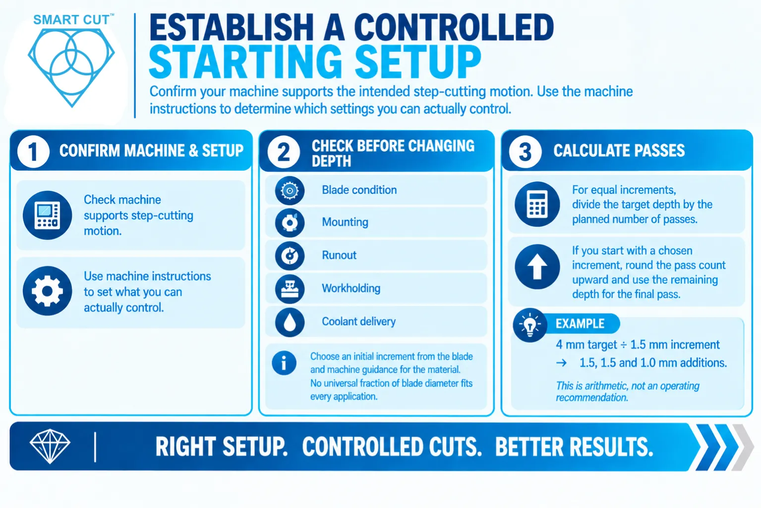
Confirm that your machine supports the intended step-cutting motion. A setup with controlled depth and repeatable traversal offers different options from a saw that feeds continuously through a specimen under an applied load. Use the machine instructions to determine which settings you can actually control.
Before changing depth, check blade condition, mounting, runout, workholding, and coolant delivery. Select an initial increment from the blade and machine guidance for the material. There is no universal fraction of blade diameter that establishes the correct increment for every precision-cutting application.
For equal increments, divide the target depth by the planned number of passes. If you begin with a chosen increment, round the required pass count upward and use the remaining depth for the final pass. A 4 mm target with a 1.5 mm increment requires 1.5, 1.5, and 1.0 mm additions. This is arithmetic, not an operating recommendation.
Measure whether a depth change improves blade life
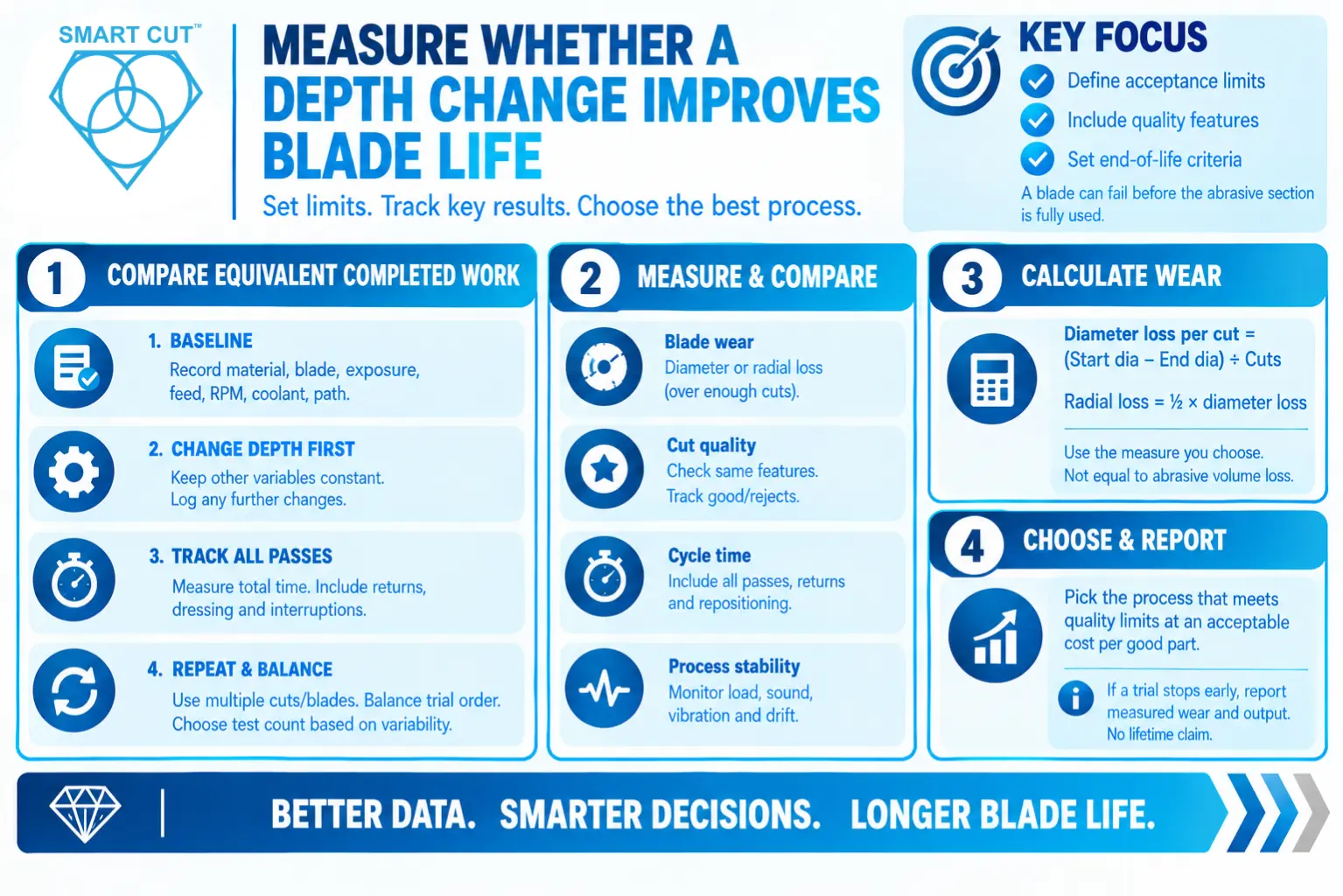
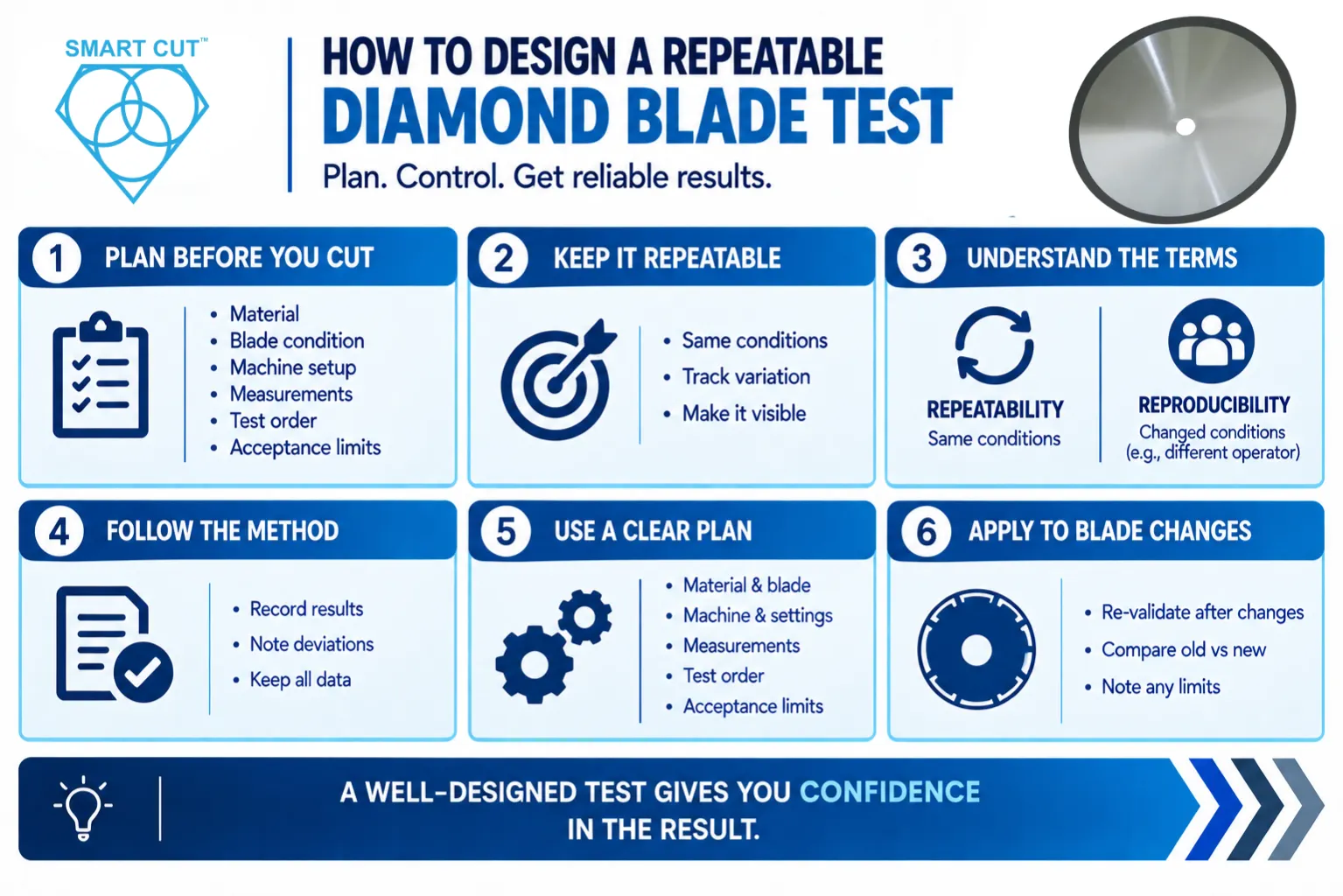
Define acceptance limits before testing. Include the cut dimensions and quality characteristics that matter to your part, such as kerf consistency, edge chipping, squareness, or surface condition. Define when the blade must be removed from service. A blade can become unusable because of quality loss or damage before its abrasive section is exhausted.
Compare equivalent completed work
- Record a baseline. Document the material and dimensions, blade specification, exposure, conditioning, feed rate, RPM, coolant conditions, and total cut path. Use representative specimens and a known blade condition.
- Change the depth schedule first. Hold other practical variables constant during the initial comparison. If you later change feed rate or RPM, record that as a separate process setting. Identify the reason for every adjustment.
- Track all passes. Measure time from the start of the first pass to completion, including returns and repositioning. Record dressing and interruptions separately. Keep warm-up, coolant condition, and inspection methods comparable.
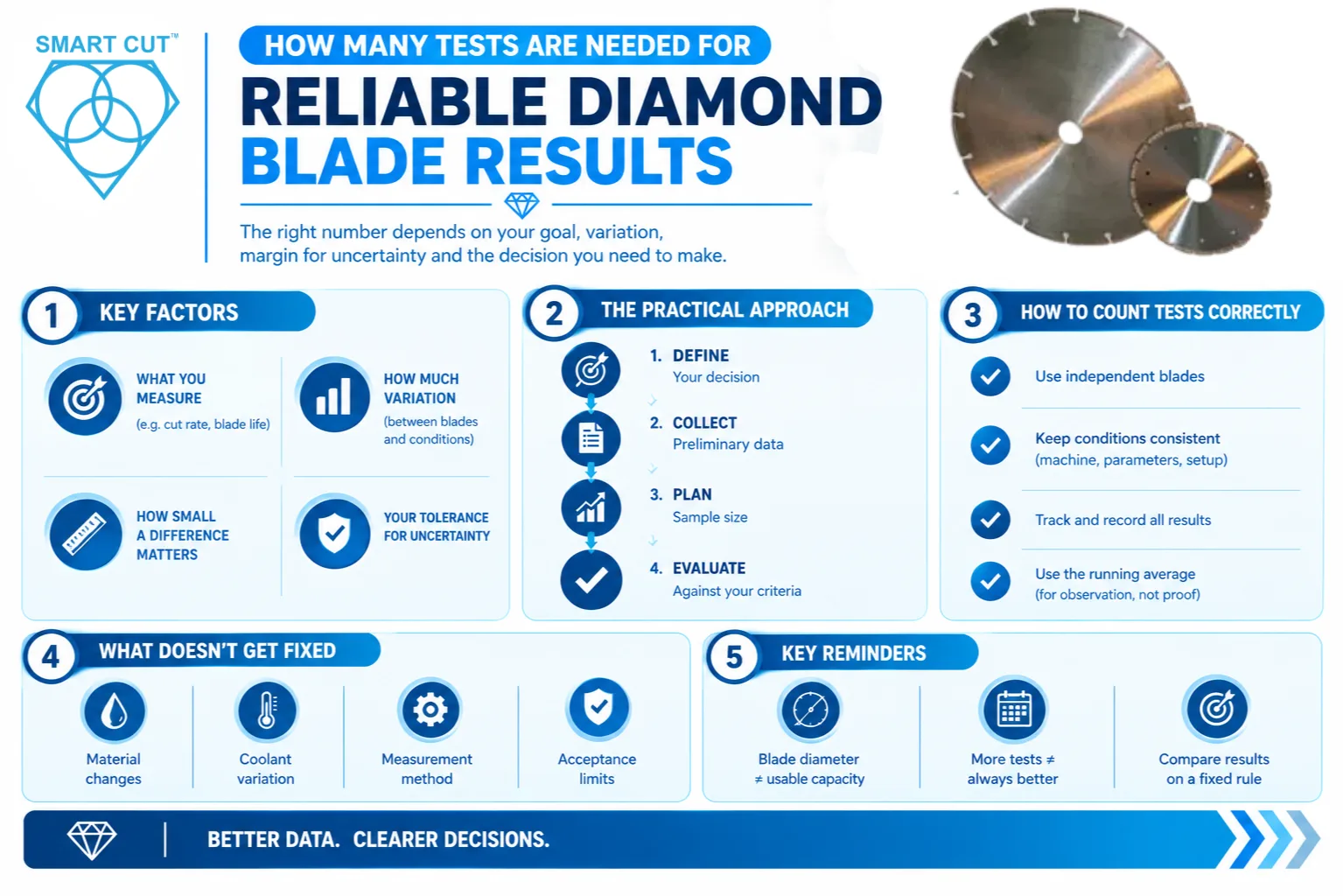
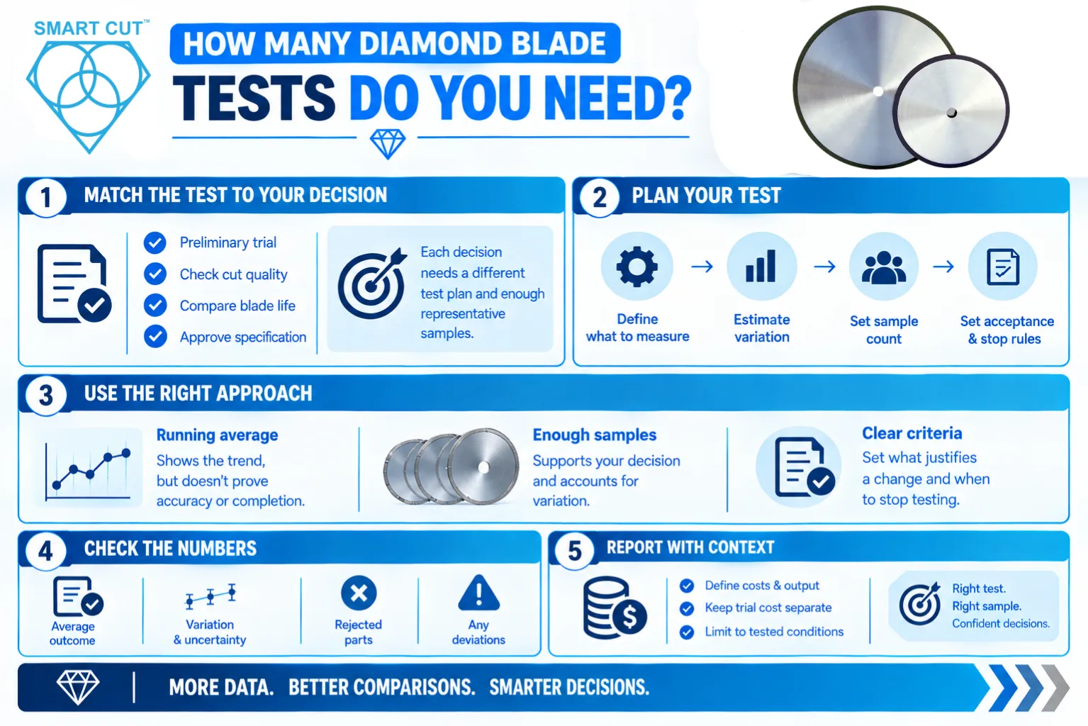
- Repeat the comparison. Use multiple completed cuts and, when possible, more than one comparable blade. Balance the order of the trials so that progressive blade wear does not consistently favor one strategy. Select the test count according to variability and the consequence of a wrong decision.
| Measure | How to compare it |
|---|---|
| Blade wear | Measure diameter or radial wear consistently over equivalent completed cuts. Use enough cutting distance for wear to exceed measurement uncertainty. |
| Cut quality | Inspect the same features and locations with the same method. Record acceptable parts, rejected parts, and the reason for rejection. |
| Cycle time | Include every cutting pass, return, and required repositioning. Include routine dressing when evaluating production cost. |
| Process stability | Track spindle load, cutting sound, vibration, and dimensional drift. Treat load as an indicator, not a direct measurement of tool life. |
For a consistent set of cuts, diameter loss per completed cut equals the starting diameter minus the ending diameter, divided by the number of completed cuts. Radial loss is half the diameter loss. State which measure you use. Neither measure is automatically equivalent to abrasive volume loss.
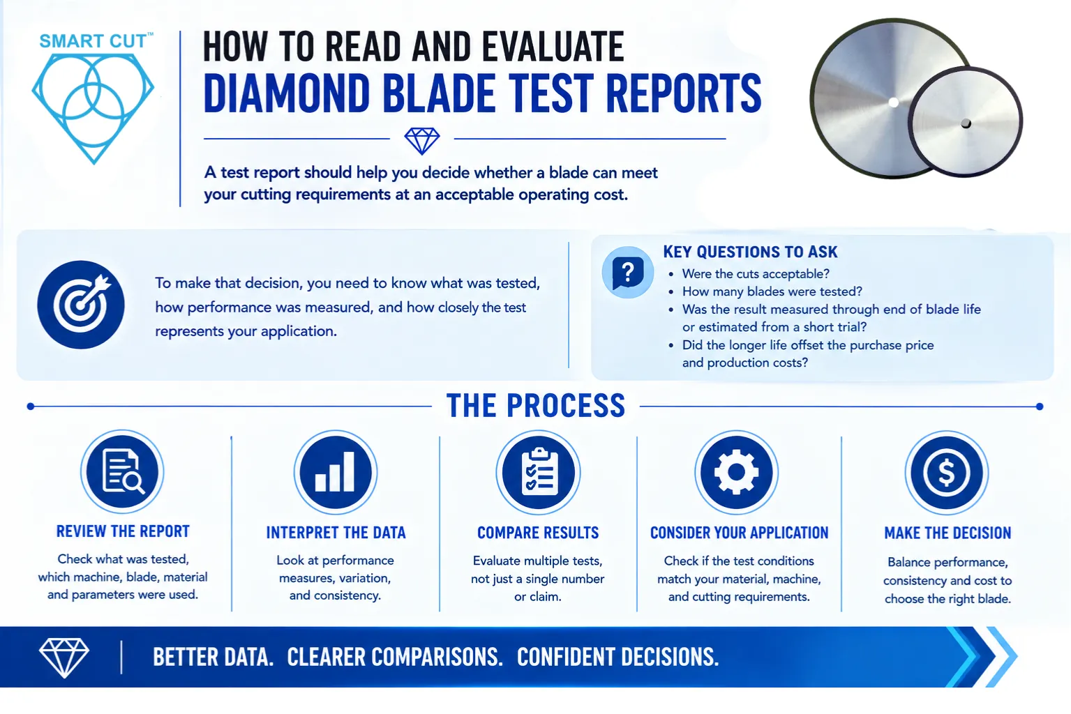
Select the process that meets quality limits at an acceptable total cost per good part. If a trial stops before either blade reaches its defined end of life, report the measured wear and output over that trial. Do not present it as a demonstrated lifetime improvement.
Chipping, heat, vibration, and rapid wear can have several causes. Use the symptom to guide inspection. A depth change is appropriate when evidence points to excessive cutting demand, but it will not correct a damaged blade, loose workholding, or an unsuitable bond.
| Observation | Check first | Depth decision |
|---|---|---|
| Load rises as the groove deepens | Coolant access, swarf buildup, side rubbing, feed rate, and blade condition. | Evaluate a smaller increment if the setup is sound and cutting demand is excessive. |
| Shiny edge and poor cutting | Glazing, loading, bond suitability, speed, and the approved conditioning method. | Do not keep reducing depth without checking whether the blade needs more effective cutting action. |
| Chipping at entry or exit | Approach feed, support near breakthrough, grit selection, mounting, and runout. | A lighter entry or final pass may help if it addresses the observed cause. |
| Wandering, vibration, or unusual noise | Blade integrity, alignment, flange condition, secure mounting, and workholding. | Stop and inspect abnormal behavior. Resume only after correcting the cause. |
| Rapid blade wear | Material abrasiveness, bond suitability, speed, coolant, and wear measurement. | Compare wear over equivalent completed cuts before assigning the cause to depth. |
Frequently Asked Questions
No. Increasing depth at unchanged feed and surface speed generally increases cutting demand, but useful blade life depends on the whole process. A stable single pass can be appropriate. Compare acceptable completed work and wear under clearly recorded conditions.
Use the blade and machine guidance for the specific material, exposure, and setup. Confirm the increment through controlled trials. Percentages such as one quarter of total depth describe a pass schedule, not a universal recommendation.
No. Each pass removes an additional depth increment, and the final pass still reaches the target depth. The blade assembly must provide sufficient usable exposure and clearance for that final penetration.
Yes. An excessively light process can promote rubbing or glazing in some blade and material combinations. It also adds traversals. Check whether the blade is cutting freely and maintaining an effective cutting surface before reducing the increment again.
Feed rate and depth affect material removal demand together. A deeper increment may require a lower feed rate. A smaller increment may permit a higher rate. Establish a controlled baseline, then evaluate adjustments within the blade and machine limits.
No. Thickness is only one factor. Blade exposure, flange support, construction, alignment, material, and coolant access also matter. A well-supported thin blade may perform well in one pass where the complete setup allows it.
No. It shows a change in process demand under the measurement conditions. Confirm any life claim with wear or end-of-life results, acceptable output, and total cycle time. Low load can also occur when a blade is rubbing without cutting efficiently.
Include blade consumption, machine and labor time, routine dressing, coolant, and the relevant cost of scrap or rework. Use the number of acceptable finished parts as the denominator. Compare complete processes that meet the same quality requirements.
Get help selecting your cutting parameters
UKAM can help you evaluate blade selection and cutting parameters for your application. Provide the material, workpiece dimensions, blade diameter and thickness, bond and grit information if known, flange size or exposure, machine, RPM, feed rate, depth schedule, coolant arrangement, and the problem you need to correct. Include photographs or inspection results when available.
Trusted by Tens of Thousands of Manufacturers, Laboratories,
Research Institutions Worldwide Since 1990
Established in 1990
RELATED ARTICLES

Brian is an experienced professional in the field of precision cutting tools, with over 27 years of experience in technical support. Over the years, he has helped engineers, manufacturers, researchers, and contractors find the right solutions for working with advanced and hard-to-cut materials. He’s passionate about bridging technical knowledge with real-world applications to improve efficiency and accuracy.
As an author, Brian Farberov writes extensively on diamond tool design, application engineering, return on investment strategies, and process optimization, combining technical depth with a strong understanding of customer needs and market dynamics.
About Brian Farberov
Brian is an experienced professional in the field of precision cutting tools, with over 27 years of experience in technical support. Over the years, he has helped engineers, manufacturers, researchers, and contractors find the right solutions for working with advanced and hard-to-cut materials. He’s passionate about bridging technical knowledge with real-world applications to improve efficiency and accuracy. As an author, Brian Farberov writes extensively on diamond tool design, application engineering, return on investment strategies, and process optimization, combining technical depth with a strong understanding of customer needs and market dynamics.
View all posts by Brian Farberov