








































Diamond Dicing Blade RPM: How Engineers Calculate Speed and Establish Cutting Parameters

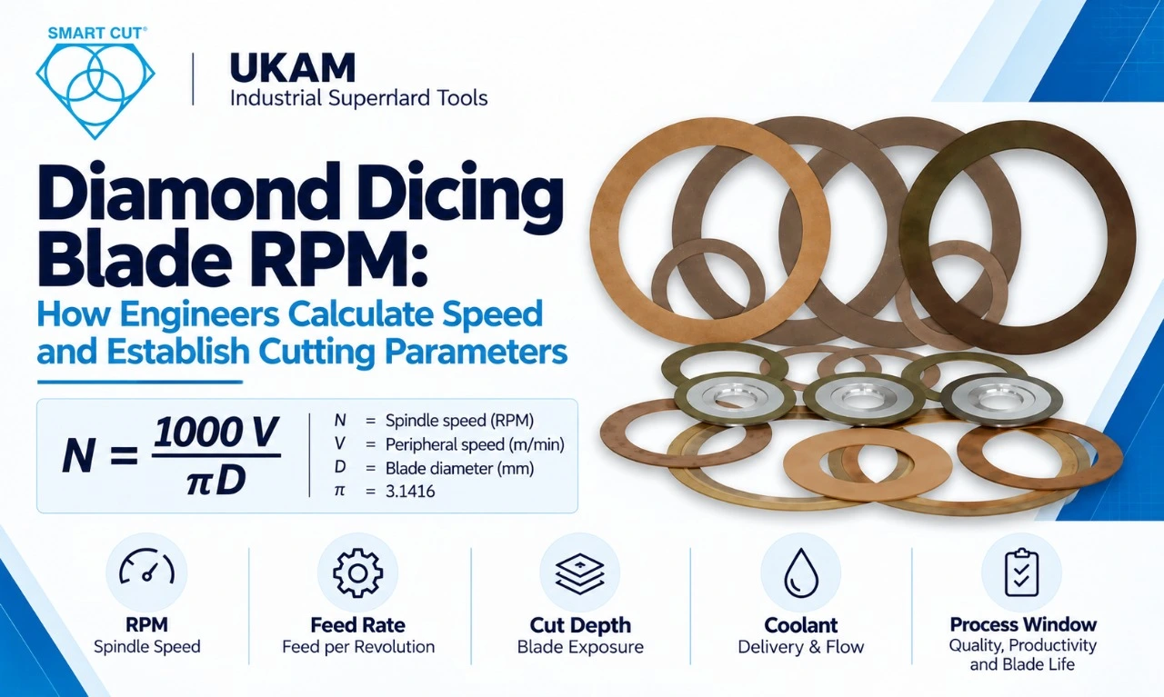
Table of Contents
Toggle
American Based Manufacturer

Established in 1990


Custom manufacturing


Spindle speed is one of the first process variables engineers set when developing a diamond dicing operation. But RPM by itself is not a cutting specification. The real cutting condition depends on blade diameter, peripheral speed, feed rate, cut depth, blade exposure, blade thickness, abrasive structure, workpiece material, coolant delivery, machine stability, and required edge quality.
Quick Answer: How Do You Calculate Diamond Dicing Blade RPM?
Choose the peripheral speed you need, then calculate RPM from the actual blade diameter:
Where:
- N = spindle speed in RPM
- V = peripheral speed in m/min
- D = blade diameter in mm
The reverse calculation, from a known RPM, is:
Worked Example
A 100 mm blade with an illustrative target of 5,000 m/min:
As a sense check, a 56 mm blade running at 30,000 RPM has a peripheral speed of approximately 5,278 m/min. Small-diameter blades on high-speed dicing spindles can therefore reach several thousand m/min at tens of thousands of RPM.
Important:
These are mathematical examples, not production recommendations. Do not use 5,000 m/min as a recommended operating speed. Always follow the blade and machine manufacturer’s specified limits and qualify the final process window for the blade, feed rate, cut depth, exposure, coolant, material, and quality requirement.
Do not copy an RPM value from one blade diameter to another without checking the resulting peripheral speed.
UKAM publishes blades across a range of diameters, thicknesses, abrasive sizes, concentrations, and bond technologies, with applications including semiconductor dicing and wafer processing.
Why Peripheral Speed Matters More Than RPM
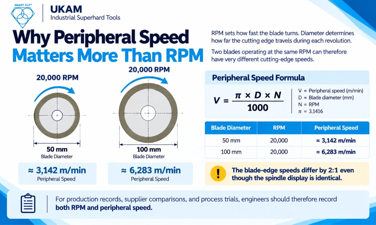
RPM sets how fast the blade turns. Diameter determines how far the cutting edge travels during each revolution. Two blades operating at the same RPM can therefore have very different cutting-edge speeds.
|
Blade Diameter |
RPM |
Peripheral Speed |
|---|---|---|
|
50 mm |
20,000 |
≈ 3,142 m/min |
|
100 mm |
20,000 |
≈ 6,283 m/min |
The blade-edge speeds differ by 2:1 even though the spindle display is identical.
For production records, supplier comparisons, and process trials, engineers should therefore record both RPM and peripheral speed.
How Blade Diameter Changes the Required RPM
At the same illustrative peripheral speed of 5,000 m/min:
|
Blade Diameter |
Calculated RPM |
|---|---|
|
50 mm |
31,831 |
|
56 mm |
28,420 |
|
75 mm |
21,221 |
|
100 mm |
15,915 |
|
125 mm |
12,732 |
|
150 mm |
10,610 |
|
200 mm |
7,958 |
For the same peripheral speed, a larger blade requires a lower RPM.
The objective is not to maximize spindle speed. It is to establish a cutting condition that balances:
|
Requirement |
What Engineers Monitor |
|---|---|
|
Cutting efficiency |
Material removal and cycle time |
|
Edge and surface quality |
Chipping, fracture, roughness, and damage |
|
Blade life |
Cuts or cutting distance |
|
Dimensional accuracy |
Kerf and cut location |
|
Thermal control |
Heat and coolant behavior |
|
Machine stability |
Runout, vibration, and spindle load |
RPM Is Only One Part of the Parameter Set
Once spindle speed is established, the remaining parameters need to be developed around it.
|
Parameter |
Engineering Question |
|---|---|
|
Blade diameter |
What diameter fits the machine and required cut? |
|
Blade thickness |
What kerf and rigidity are required? |
|
RPM |
What spindle speed gives the target peripheral speed? |
|
Feed rate |
How fast should the workpiece move through the blade? |
|
Cut depth |
How much material is removed per pass? |
|
Blade exposure |
How far does the blade extend beyond the flanges? |
|
Coolant |
Is the cutting zone cooled and flushed effectively? |
|
Workpiece support |
Is the material supported during and at the end of the cut? |
|
Blade specification |
Are grit, bond, and concentration appropriate? |
|
Quality limit |
What chipping, kerf, and dimensional limits apply? |
This is where RPM becomes part of an actual process-development program rather than an isolated machine setting.
RPM and Feed Rate Must Be Developed Together
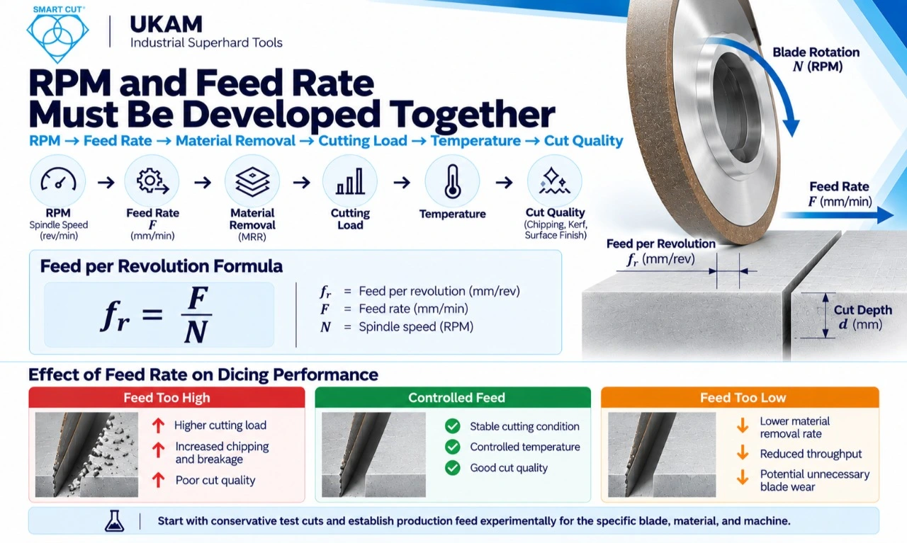
The useful engineering chain is:
RPM → feed rate → material removal → cutting load → temperature → cut quality
Raising RPM without reviewing feed changes the cutting condition. Likewise, increasing feed at constant RPM increases the work performed by the blade.
Excessive feed can increase chipping and breakage, while very low feed can reduce throughput and contribute to unnecessary blade wear.
Start with conservative test cuts, particularly on brittle materials, and establish production feed experimentally for the specific blade, material, and machine.
Feed per Revolution
Feed per revolution normalizes feed against spindle speed and makes conditions easier to compare when RPM changes:
fr = F/N
For example, a feed of 50 mm/s equals 3,000 mm/min. At 30,000 RPM:
fr = 3,000/30,000 = 0.1 mm/rev
Do not judge feed per revolution in isolation. Blade thickness, abrasive size, cut depth, material brittleness, support, and edge-quality limits also define the acceptable process window.
Material Removal
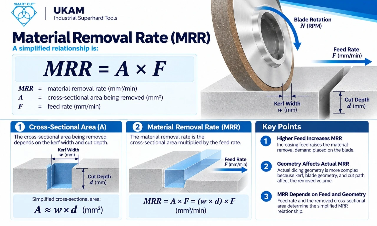
Actual dicing geometry is more complex because kerf, blade geometry, and cut path affect removed volume. However, the relationship demonstrates why increasing feed raises the material-removal demand placed on the blade.
where:
- MRR = material removal rate
- A = cross-sectional area being removed
- F = feed rate
Actual dicing geometry is more complex because kerf, blade geometry, and cut path affect removed volume. However, the relationship demonstrates why increasing feed raises the material-removal demand placed on the blade.
Cut Depth, Blade Exposure, and Stability
A shallow cut and a full-thickness cut can load the blade very differently even at identical RPM and feed.
During qualification, record:
- Measured workpiece thickness
- Cutting depth
- Number of passes
- Actual blade exposure
- Support type, such as tape, carrier, fixture, or substrate
- Entry condition
- Exit condition
On brittle materials, the exit condition deserves particular attention because the final portion of a cut can fracture differently from the entry.
Blade Exposure
Blade exposure is the amount of blade extending beyond the mounting flanges.
Greater exposure provides clearance for deeper cuts, but excessive exposure can increase sensitivity to deflection and vibration.
|
Condition |
Engineering Consideration |
|---|---|
|
Shallow cut |
Lower exposure may provide greater stability |
|
Deep cut |
Greater exposure may be necessary |
|
Thin blade |
Exposure becomes more sensitive |
|
High RPM |
Mounting and balance become more important |
|
Brittle material |
Stability is critical for fracture control |
|
Tight kerf |
Runout and deflection require close control |
Evaluate the blade as a rotating cutting structure, not simply as an abrasive edge.
Runout and Machine Condition
A correctly specified blade can still perform poorly on an unsuitable machine.
Before changing cutting parameters, inspect:
- Spindle runout
- Blade mounting
- Flange condition
- Blade balance
- Arbor fit
- Workpiece support
- Machine vibration
- Machine rigidity
Thin blades are particularly sensitive because small lateral movement becomes significant relative to the kerf. At high RPM, balance and mounting accuracy become even more important.
Changing the blade specification should therefore not automatically be the first response to every chipping problem.
How RPM Can Affect Chipping
Chipping is a multi-variable failure mode.
Potential contributors include:
- RPM
- Feed rate
- Blade grit
- Bond characteristics
- Blade thickness
- Cut depth
- Workpiece support
- Material brittleness
- Coolant delivery
- Machine vibration
Higher spindle speed can sometimes reduce the material removed per abrasive engagement at a given feed, but the result depends on the entire process.
Higher RPM is not automatically a cure for chipping.
A controlled trial is the reliable way to determine whether speed is helping.
|
Metric |
Trial A |
Trial B |
|---|---|---|
|
RPM |
20,000 |
30,000 |
|
Feed |
15 mm/s |
25 mm/s |
|
Cycle time |
4.8 min |
3.4 min |
|
Blade cost |
$220 |
$240 |
|
Acceptable cuts per blade |
6,000 |
5,500 |
|
Scrap rate |
2.0% |
1.8% |
|
Tool cost per acceptable cut |
$0.0374 |
$0.0445 |
The process may have an optimum operating window rather than following a rule that higher RPM is always better.
Blade Wear and Cost Per Acceptable Cut
When RPM changes, monitor:
- Blade wear
- Cutting distance
- Blade diameter loss
- Kerf stability
- Chipping
- Surface finish
- Cycle time
- Scrap
A speed increase that reduces cycle time but shortens blade life may or may not improve production economics.
A useful comparison is tool cost per acceptable cut.
|
Technology |
Published characteristic |
Engineering evaluation |
|---|---|---|
|
Diamonds are mixed and sintered with specific metal alloys |
Abrasive retention, exposure, wear, tool life |
|
|
Organic matrix based on resin, fillers, and abrasive grains |
Surface finish, cutting behavior, heat, dressing |
|
|
Electroplated |
Diamond or CBN retained through a plated working layer |
Abrasive exposure, geometry, working-layer wear |
|
Brazed bond |
Diamond bonded to the tool body with high exposure |
Particle exposure, retention, geometry, wear |
|
Hybrid bond |
Combines characteristics of different bond systems |
Cutting behavior, finish, durability, process stability |
|
Vitrified bond |
Rigid bonded abrasive structure |
Form retention, dressing, finish, wear |
|
PCD/PCBN |
Polycrystalline diamond or CBN cutting material |
Geometry, edge behavior, wear, machining application |
|
CVD diamond |
Diamond coating deposited through chemical vapor deposition |
Coating condition, wear, application compatibility |
|
SMART CUT |
UKAM technology using controlled diamond orientation within the matrix |
Abrasive exposure, consistency, wear behavior, application response |
Trial B is faster but has a higher tooling cost per acceptable cut. It could still be the better production choice if the machine-time savings outweigh the additional tooling cost.
Evaluate:
cycle time + blade life + scrap + machine cost + acceptable production
rather than RPM alone.
Coolant Delivery at Higher Cutting Speeds
Coolant can:
- Remove heat
- Evacuate debris
- Lubricate the cutting zone where applicable
- Clean the blade
- Control workpiece temperature
High spindle speed combined with inadequate coolant can create thermal instability or poor debris evacuation.
Record the following during every process trial:
|
Coolant Variable |
Measurement |
|---|---|
|
Coolant type |
Exact product |
|
Concentration |
Measured percentage |
|
Flow |
L/min |
|
Pressure and temperature |
Actual values |
|
Filtration |
Filter specification |
|
Nozzle position |
Relative to cutting zone |
|
Delivery |
Flood or directed |
Coolant delivery should be treated as a process variable rather than an afterthought.
Material-Specific RPM Considerations
The same RPM should not automatically be applied to every material.
Hardness, brittleness, thermal behavior, fracture characteristics, and abrasiveness can all shift the acceptable process window.
|
Material |
Potential Failure Modes |
What to Evaluate |
|---|---|---|
|
Wafer-edge chipping and cracking |
RPM with feed, blade thickness, grit, support, and edge condition |
|
|
Silicon carbide |
Edge chipping and subsurface damage |
Blade wear and cutting stability throughout qualification |
|
Sapphire |
Edge chipping and subsurface fracture |
RPM, feed, blade structure, and workpiece support together |
|
Edge fracture and cracking |
Stable cutting conditions rather than maximum feed |
|
|
Edge breakout and grain-related fracture |
RPM with grit size, bond behavior, feed, and support |
|
|
GaAs and other brittle semiconductors |
Edge fracture and wafer breakage |
Conservative initial feed and controlled qualification |
For silicon, the goal is stable cutting with controlled edge damage, not maximum material removal.
For silicon carbide, blade wear and cutting stability should be monitored throughout qualification because of the material’s extreme hardness.
For sapphire, RPM, feed, blade structure, and support should be treated as one system.
For glass and quartz, fracture control is generally more important than simply maximizing feed.
Match the Blade Bond to the Speed Window
Bond type influences how a blade responds to speed and feed.
The following ranges are based on UKAM’s published specification information for its dicing blade bond families. Confirm the exact limits for the specific part number before using them as design inputs.
|
Specification |
Sintered Metal | Hybrid Bond | Nickel Bond | |
|---|---|---|---|---|
|
Abrasive size |
3–151 µm |
3–126 µm |
3–151 µm |
3–70 µm / 2–50 µm |
|
Concentration |
25–200 con |
25–200 con |
25–200 con |
100–250 con |
|
Minimum thickness |
.003" (.076 mm) |
.004" (.101 mm) |
004" (.101 mm) |
.0003" (.0076 mm) |
|
Typical character |
The practical response of each bond depends on the complete blade specification and application.
For specification development, engineers should consider:
- Abrasive size
- Diamond concentrationDiamond concentration
- Bond type
- Blade thickness
- Diameter
- Exposure
- Material
- Feed
- RPM
- Coolant
- Required edge quality
Build a Process Window, Not a Single Number
Develop a process window rather than declaring one RPM universally correct.
The following is an illustrative example:
|
Parameter |
Low |
Starting Point |
High |
|---|---|---|---|
|
RPM |
20,000 |
25,000 |
30,000 |
|
Feed |
10 mm/s |
20 mm/s |
30 mm/s |
|
Cut depth |
0.30 mm |
0.50 mm |
0.60 mm |
|
Coolant flow |
1.0 L/min |
1.5 L/min |
2.0 L/min |
|
Maximum chipping |
35 µm |
25 µm |
25 µm |
|
Target blade life |
5,000 cuts |
7,000 cuts |
6,000 cuts |
The machine’s maximum spindle speed is a constraint, not a process target.
The actual process limit may come from:
- Uneven wheel contact
- Dimensional variation
- Localized wheel wear
- Surface waviness
- Edge damage
- Inconsistent grinding forces
- Mounting system
- Workpiece characteristics
- Coolant delivery
- Quality requirements
- Production economics
How to Qualify a Diamond Dicing Blade RPM
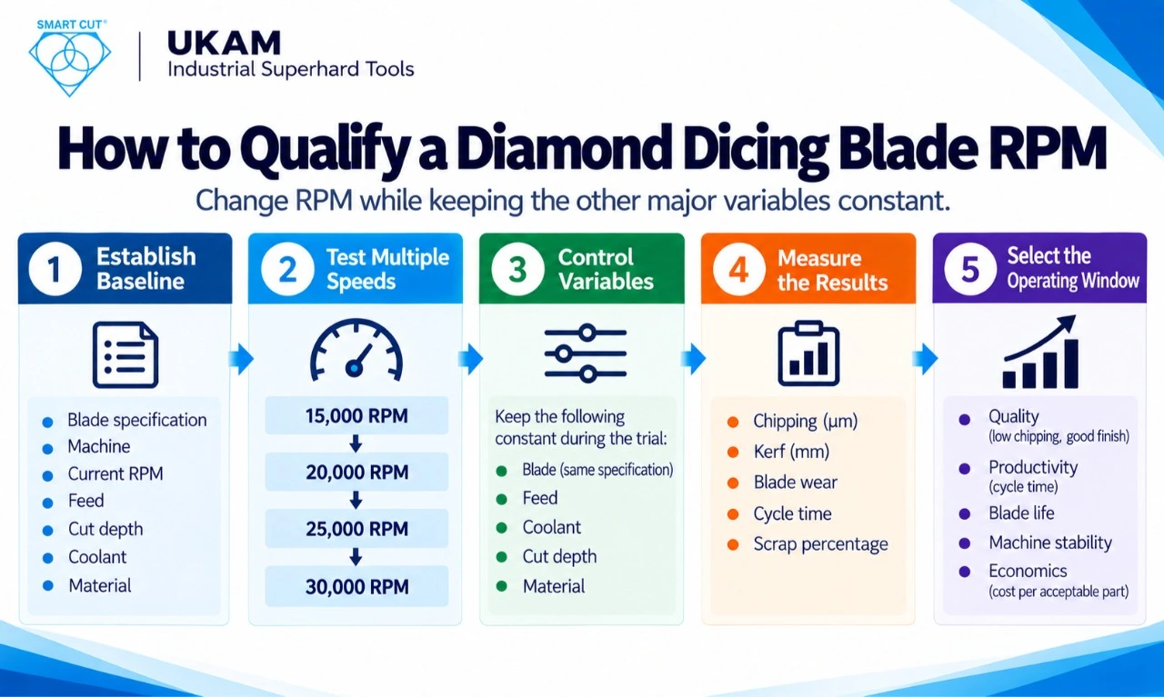
A controlled qualification trial changes RPM while holding the other major variables as constant as practical.
Do not change RPM, grit, feed, coolant, blade thickness, and cut depth simultaneously. If multiple variables change at once, it becomes difficult to determine which variable caused the result.
Phase 1: Establish a Baseline
Record:
- Blade specification
- Machine
- Current RPM
- Feed
- Cut depthCut depth
- Coolant
- Material
- Chipping
- Kerf
- Blade life
Phase 2: Test Multiple Speeds
A trial range might include:
Phase 3: Control Variables
Hold everything except RPM constant wherever practical.
Phase 4: Measure the Results
Measure:
- Chipping in µm
- Kerf in mm
- Surface finish in Ra
- Blade wear in mm or cuts
- Cycle time
- Scrap percentage
- Spindle load
- Coolant temperature
- Acceptable part count
Phase 5: Select the Operating Window
Select the RPM range that meets the combined requirements for:
- Quality
- Productivity
- Blade life
- Machine stability
- Economics
This turns RPM selection from trial-and-error into a documented engineering qualification.
Signs That RPM May Be Too High
|
Observation |
Possible Cause to Investigate |
|---|---|
|
Increased vibration |
Speed, balance, or mounting issue |
|
Rising temperature |
Coolant or process condition |
|
Increased chipping |
Speed, feed, or blade condition |
|
Reduced blade life or unexpected wear |
Excessive load or blade specification mismatch |
|
Kerf instability |
Deflection, runout, or blade condition |
|
Spindle-load instability or surface damage |
Machine, abrasive, or process mismatch |
None of these observations proves RPM is the cause. They indicate that RPM should be included in the diagnostic investigation alongside the other process variables.
Pre-Increase Checklist
Before increasing spindle speed, verify the following.
Machine and Blade
- Blade speed rating and machine maximum RPM verified
- Spindle runout measured
- Flanges, arbor, and blade mounting inspected
- Blade balance and machine vibration checked
- Diameter, thickness, bond, grit, concentration, and exposure verified
Process
- Peripheral speed and RPM calculated
- Feed and cut depth established
- Coolant flow verified
- Workpiece support confirmed
Quality and Production
- Kerf measured
- Chipping measured
- Surface quality evaluated
- Dimensional accuracy evaluated
- Cracking evaluated
- Scrap recorded
- Cycle time recorded
- Blade life recorded
- Acceptable cuts recorded
- Cost per acceptable cut calculated
- Process window documented
Common Mistakes When Setting Dicing Blade RPM
|
Mistake |
Why It Matters |
|---|---|
|
Copying RPM from another blade |
A different diameter produces a different peripheral speed. |
|
Looking only at RPM |
Peripheral speed is the better comparison across blade diameters. |
|
Changing RPM without reviewing feed |
RPM and feed interact in the cutting condition. |
|
Defaulting to maximum machine RPM |
Maximum spindle speed is not automatically the optimum. |
|
Ignoring exposure and runout |
Both strongly affect thin precision blades. |
|
Changing RPM and grit together |
You cannot isolate which change caused the result. |
|
Measuring only cycle time |
A faster cut is not better if chipping, scrap, or blade cost rises. |
|
Ignoring coolant |
Higher cutting speeds increase the importance of thermal management and debris removal. |
|
Using one RPM for every material |
Silicon, SiC, sapphire, ceramics, quartz, and glass require different process windows. |
When Custom Dicing Blade Development May Be Necessary
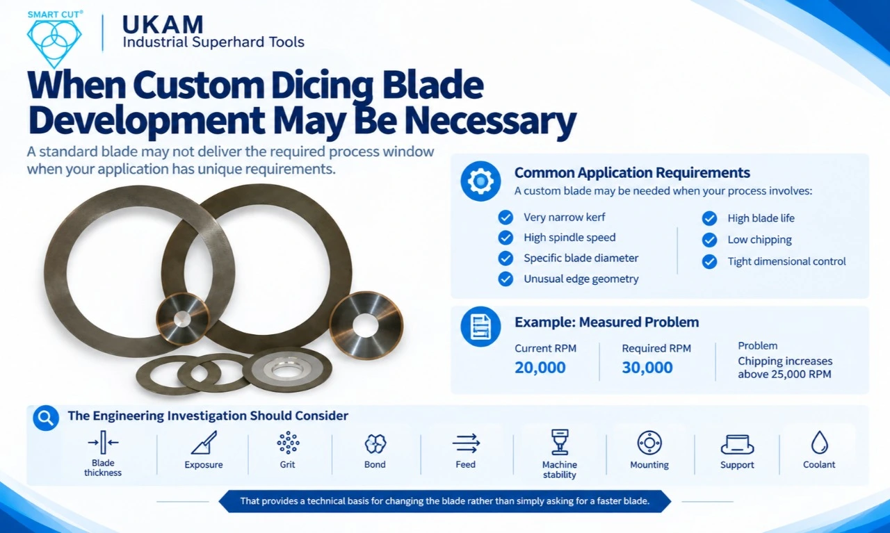
A standard blade may not deliver the required process window when an application combines requirements such as:
- Very narrow kerf
- High spindle speed
- Specific blade diameter
- Unusual edge geometry
- High blade life
- Low chipping
- Tight dimensional control
Begin with measured requirements.
For example:
- Current RPM: 20,000
- Required RPM: 30,000
- Problem: Chipping increases above 25,000 RPM
The engineering investigation should then consider:
- Blade thickness
- Exposure
- Grit
- Bond
- Feed
- Machine stability
- Mounting
- Support
- Coolant
That provides a technical basis for changing the blade rather than simply asking for a faster blade.
Frequently Asked Questions
Use:
where N is RPM, V is peripheral speed in m/min, and D is blade diameter in mm.
Always check the calculated result against the applicable blade and machine speed limits.
No.
For the same peripheral speed, a larger blade requires a lower RPM.
RPM describes spindle rotation.
Peripheral speed is the linear velocity of the blade edge and is calculated from RPM multiplied by blade circumference, with the appropriate unit conversion.
Sometimes, but not universally.
Feed rate, grit, bond, blade thickness, support, coolant, machine stability, and material condition also affect edge damage. The effect of RPM should therefore be established through a controlled trial.
Yes.
If the target peripheral speed remains constant, recalculate RPM whenever blade diameter changes.
Not directly in the peripheral-speed equation.
However, blade thickness affects stiffness, deflection, and stability. A thin blade operating at high speed therefore requires appropriate mounting, support, and machine stability.
No.
Use the speed that meets quality, productivity, blade-life, and cost targets while remaining within the blade and machine limits.
Engineering Principles to Remember
- Calculate peripheral speed before selecting RPM, and always interpret RPM together with blade diameter.
- Develop RPM and feed as one combined process condition.
- Control exposure, runout, and mounting accuracy, particularly with thin precision blades.
- Do not assume higher RPM is better. Treat machine maximum RPM as a constraint.
- Measure chipping, kerf, blade life, cycle time, and scrap during every RPM trial.
- Evaluate coolant delivery alongside cutting speed.
- Expect each material to require its own process window.
- Judge economics by cost per acceptable cut.
- Never transfer published RPM values blindly between blades, machines, materials, or operating conditions.
Final Takeaway
Treat RPM as part of a controlled cutting process, not as an isolated machine setting.
The engineering sequence is:
Blade diameter → target peripheral speed → calculated RPM → feed rate → cut depth → coolant → machine stability → quality measurement → production qualification
The calculation itself is straightforward. The engineering work is determining the speed and cutting conditions that consistently produce acceptable results for the specific material, blade, machine, quality requirement, and production cost target.
The objective is not the fastest RPM.
It is the RPM and cutting condition that consistently produces acceptable parts at the required production cost.
Trusted by Tens of Thousands of Manufacturers, Laboratories,
Research Institutions Worldwide Since 1990
American Based Manufacturer
Established in 1990
