




















Diamond Blades for Precision Manufacturing: How to Select Bond, Grit, Geometry, and Cutting Parameters

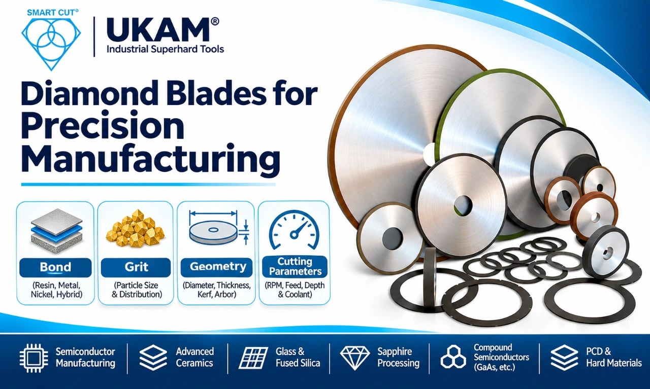
Table of Contents
Toggle
American Based Manufacturer

Established in 1990


Custom manufacturing


The Engineering Problem: Selecting Diamond Blades Without Compromising Cut Quality or Production Cost
Selecting diamond blades for precision manufacturing is not simply a matter of choosing the hardest abrasive or the blade with the longest advertised service life. The blade must remove material at a controlled rate while maintaining dimensional accuracy, acceptable edge quality, manageable cutting forces and predictable wear.
A blade that cuts quickly but produces excessive chipping may increase inspection rejects and secondary finishing. A blade with a long service life may still be uneconomical if it requires frequent dressing, creates a wide kerf or increases cycle time. Similarly, a thin blade may reduce material loss but become unstable if the machine, mounting system or cutting conditions cannot support it.
These tradeoffs become particularly important when machining silicon carbide (SiC), alumina, silicon nitride, tungsten carbide, sapphire, fused silica, gallium arsenide (GaAs), polycrystalline diamond (PCD) and other hard or brittle materials.
The correct specification must account for the complete cutting system:
- Workpiece material, grade and microstructure
- Blade bond, diamond grit and concentration
- Blade diameter, thickness and cutting geometry
- Machine spindle, flange and runout
- RPM, feed rate and depth of cut
- Coolant delivery and workpiece support
- Required edge quality, dimensional tolerance and production volume
The objective is to qualify a blade that delivers the required number of acceptable components at the lowest sustainable process cost.
When Should Engineers Reconsider Their Existing Diamond Blade?
A blade specification that performed well during initial trials may become unsuitable after a material change, production increase, machine modification or tighter quality requirement.
Engineers should investigate blade selection when measurable process indicators begin to change.
|
Production trigger |
What may be happening |
What to investigate |
|---|---|---|
|
Increasing edge chipping |
Excessive cutting stress, unsuitable grit or unstable workpiece support |
Grit size, bond behaviour, feed and fixturing |
|
Longer cutting time |
Glazing, loading, abrasive wear or reduced cutting efficiency |
Diamond exposure, dressing and spindle condition |
|
Shorter blade life |
Excessive bond wear, thermal loading or unsuitable concentration |
Bond formulation, coolant and cutting load |
|
Inconsistent kerf width |
Blade deflection, runout or mounting variation |
Blade thickness, flange condition and spindle runout |
|
More subsurface damage |
Aggressive abrasive engagement or excessive cutting force |
Grit, feed, material support and inspection method |
|
Higher scrap rate |
Unstable process conditions or inadequate edge control |
Complete process capability and blade specification |
|
More frequent dressing |
Bond is not exposing fresh diamond at the required rate |
Bond hardness, material abrasiveness and dressing method |
Engineering principle: Do not change the blade specification simply because cutting performance has deteriorated. First establish whether the cause is the blade, machine, mounting, coolant, workpiece condition or operating parameters.
Establish a Baseline Before Changing the Blade
A meaningful blade comparison requires a documented baseline. Without consistent starting conditions, a trial can produce misleading results because the machine setup or workpiece condition may have changed between tests.
Record the following information before evaluating a replacement blade.
|
Parameter category |
Information to record |
Why it matters |
|---|---|---|
|
Workpiece |
Material, grade, hardness, thickness and structure |
Determines abrasive and bond requirements |
|
Blade geometry |
Outside diameter, inside diameter, thickness and kerf |
Affects stability, material loss and machine compatibility |
|
Abrasive specification |
Diamond grit, concentration and type |
Influences cutting action and surface damage |
|
Bond |
Resin, sintered metal, nickel electroplated or hybrid |
Controls abrasive retention and wear behaviour |
|
Machine |
Saw model, spindle power, RPM and flange arrangement |
Establishes operating limits |
|
Machine condition |
Spindle runout, flange condition and vibration |
Affects cut accuracy and blade stability |
|
Cutting conditions |
Feed rate, depth of cut and coolant delivery |
Influences cutting force and thermal behaviour |
|
Quality |
Chipping, kerf width, surface finish and subsurface damage |
Defines acceptance criteria |
|
Production |
Cycle time, blade life, dressing and scrap rate |
Establishes operating cost |
Important geometric and process calculations
Peripheral speed
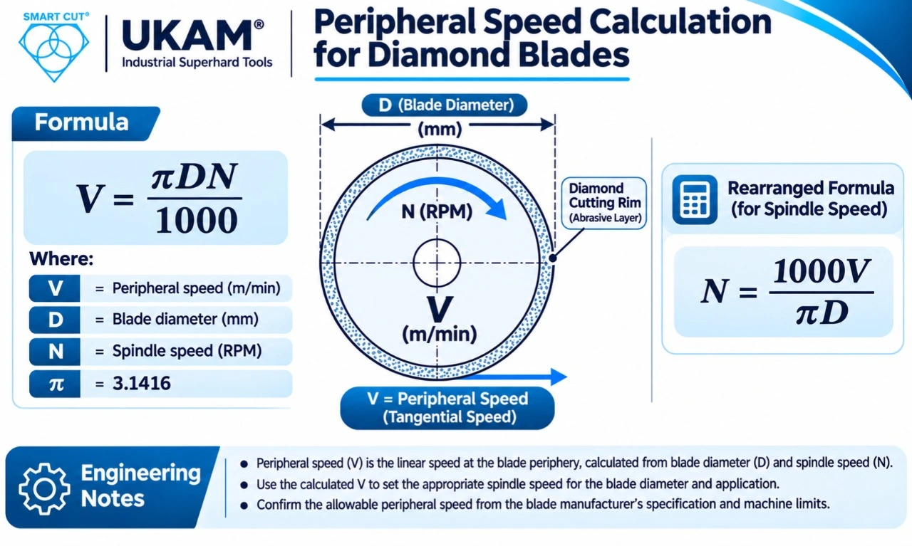
Where:
V = peripheral speed in m/min
D = blade diameter in mm
N = spindle speed in RPM
For example, a 100 mm diameter blade running at 20,000 RPM has a calculated peripheral speed of approximately 6,283 m/min, or 104.7 m/s.
This calculation describes blade speed at the outside diameter. It does not establish that the blade is approved to operate at that speed. Always follow the manufacturer’s maximum rated RPM for the exact blade specification and diameter.
Feed per revolution
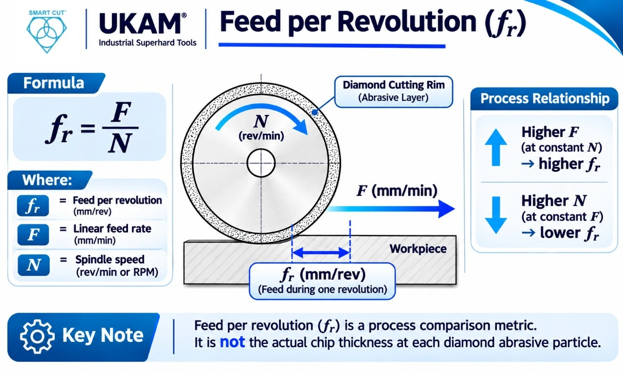
Where:
fr= feed per revolution
F = linear feed rate per minute
N = spindle RPM
This provides a useful process comparison when evaluating changes in feed and spindle speed. It should not be treated as the actual chip thickness at each diamond particle.
Material removal rate
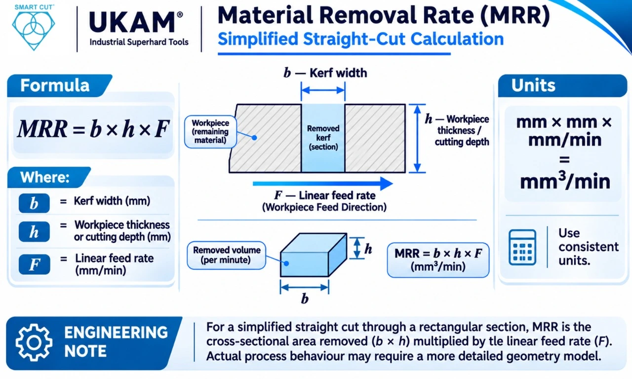
For a simplified straight cut through a rectangular section:
MRR = b × h × F
Where:
b = kerf width
h = workpiece thickness or cutting depth
F = linear feed rate
Use consistent units to obtain a meaningful volume removal rate.
Kerf material loss
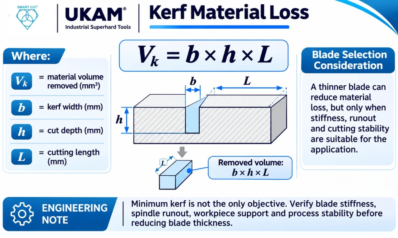
- VK = material volume removed
- b = kerf width
- h = cut depth
- L = cutting length
Compare Diamond Blades by Cost Per Accepted Part
The purchase price of a diamond blade is not a reliable measure of its manufacturing cost. Engineers should compare the total cost of producing acceptable components.
A lower priced blade may have a higher operating cost if it wears quickly, requires frequent dressing or increases cycle time. Conversely, a higher priced blade may provide a lower cost per accepted component through longer usable life and reduced rejection.
Illustrative supplier comparison
The following example uses hypothetical values to demonstrate the calculation. These are not UKAM customer results, product quotations or guaranteed performance figures.
|
Cost input |
Supplier A |
Supplier B |
|---|---|---|
|
$180 |
$260 |
|
|
Usable cuts per blade |
800 |
1,500 |
|
Dressing cost |
$8 per 100 cuts |
$8 per 300 cuts |
|
Cutting cycle time |
55 seconds |
43 seconds |
|
Scrap rate |
5% |
2% |
|
Machine operating rate |
$75/hour |
$75/hour |
|
Workpiece material cost |
$12 |
$12 |
Cost calculation
Blade cost per attempted component:
Dressing cost per attempted component:
Machine cost per attempted component:
\[ C_m = \frac{\text{Cycle time in seconds}}{3600} \times \text{Machine hourly rate} \]
Cost per accepted component:
- Ca = cost per accepted component
- Cw = workpiece material cost
- S = scrap rate expressed as a decimal
|
Calculated cost |
Supplier A |
Supplier B |
|---|---|---|
|
Blade cost per attempted component |
$0.225 |
$0.173 |
|
Dressing cost per attempted component |
$0.080 |
$0.027 |
|
Machine cost per attempted component |
$1.146 |
$0.896 |
|
Material cost per attempted component |
$12.000 |
$12.000 |
|
Cost per accepted component |
$14.16 |
$13.36 |
In this example, Supplier B has a higher purchase price but produces an estimated 5.7% lower cost per accepted component.
The calculation excludes labour, blade changeover, inspection, coolant, maintenance, downstream finishing and other overheads. If these costs differ between suppliers, they should be added to the model.
Engineering insight: The correct purchasing decision is not necessarily the blade with the lowest price or longest life. It is the blade that consistently meets quality requirements at the lowest total production cost.
How to Select the Correct Diamond Blade Bond, Grit and Geometry
The blade specification must match the material removal mechanism, required surface quality and operating conditions. Bond type is important, but it should never be selected independently of grit size, concentration, geometry and machine capability.
Diamond blade bond comparison
|
Bond type |
General characteristics |
Engineering considerations |
|---|---|---|
|
Bond wears to expose fresh diamond; often selected for fine cutting and surface quality |
Evaluate heat generation, wear rate, cut quality and dressing requirements |
|
|
Diamond is distributed through a metal matrix with multiple abrasive layers |
Consider abrasive wear, bond hardness, form retention and dressing |
|
|
Commonly uses a single exposed abrasive layer retained by nickel |
Useful where exposed diamond and free cutting action are required; evaluate usable abrasive depth |
|
|
Hybrid bond |
Combines characteristics of different bond systems |
Evaluate the specific construction and documented application results rather than relying on the hybrid label |
|
Diamond is retained through a brazed interface |
Assess abrasive exposure, retention and suitability for the particular blade design |
Grit size
Grit selection influences cutting rate, surface finish and the scale of material damage.
- Coarser diamond particles generally provide more aggressive material removal but can increase edge damage and surface roughness.
- Finer diamond particles can support improved surface quality and reduced chipping, although they may reduce cutting efficiency under some conditions.
- The correct grit depends on material microstructure, blade construction, feed rate and acceptance criteria.
Diamond concentration
Concentration affects the number of active abrasive particles and the load carried by individual particles. Its effect is not a simple rule that higher concentration always means longer life.
The appropriate concentration depends on bond design, workpiece properties, cutting forces and the required balance between cutting rate and finish.
Blade geometry
|
Geometry variable |
Selection consideration |
|---|---|
|
Outside diameter |
Must provide the required cutting depth and comply with machine speed limits |
|
Blade thickness |
Controls nominal kerf and contributes to lateral stiffness |
|
Inside diameter |
Must match the spindle or arbor accurately |
|
Core and rim construction |
Must provide suitable support and abrasive exposure |
|
Blade exposure |
Excessive unsupported exposure can increase deflection and vibration |
|
Tolerance and runout |
Influence kerf consistency and dimensional accuracy |
A thin blade is not automatically the best choice for precision work. If the blade deflects under cutting load, the resulting kerf variation may outweigh the material savings.
A Step-by-Step Method for Qualifying Diamond Blades
A controlled qualification process makes supplier comparisons more reliable and helps prevent unnecessary changes to production settings.
Step 1: Define the operation
Establish whether the application involves wafer dicing, cut-off sectioning, precision slicing, trimming or another cutting process. Different operations impose different requirements on blade geometry and construction.
Step 2: Identify the workpiece material
Record the exact material grade, composition, thickness, condition and relevant microstructural characteristics. A generic material name is not sufficient for a final specification.
Step 3: Establish quality requirements
Define maximum edge chipping, kerf tolerance, surface finish, subsurface damage limits and dimensional acceptance criteria. Specify how each requirement will be measured.
Step 4: Check machine compatibility
Confirm blade diameter, arbor size, thickness, flange support, spindle power, runout and rated operating speed. Do not exceed the manufacturer’s blade speed rating.
Step 5: Select a starting specification
Choose a suitable bond family, grit range, concentration and blade geometry using the workpiece and process requirements. Obtain the manufacturer’s recommendation for the exact application.
Step 6: Conduct controlled cutting trials
Keep the machine, fixture, coolant and workpiece conditions consistent. Change one major variable at a time where practical so that the influence of the blade specification can be identified.
Step 7: Measure performance
Record cutting time, edge damage, kerf width, surface condition, blade wear, dressing frequency and usable tool life. Use the same inspection method for every candidate.
Step 8: Validate production economics
Calculate cost per accepted component, including relevant tool, machine, material, labour, dressing and quality costs. Confirm the result over enough production cycles to capture normal process variation.
Material-Specific Diamond Blade Selection and Common Failure Modes
Material hardness alone does not determine blade selection. Brittleness, fracture behaviour, abrasiveness, porosity, grain structure and thermal sensitivity can all influence cutting performance.
|
Material |
Common cutting problems |
What engineers should evaluate |
|---|---|---|
|
Silicon carbide (SiC) |
Edge chipping, subsurface microcracking and rapid abrasive wear |
Bond wear behaviour, grit, feed, coolant and machine rigidity |
|
Alumina (Al₂O₃) |
Grain pullout, intergranular fracture and edge breakout |
Purity, density, grain structure, grit and cutting force |
|
Silicon nitride (Si₃N₄) |
Localized edge fracture and microcracking |
Material grade, toughness, blade sharpness and feed stability |
|
Tungsten carbide |
Carbide grain fracture, binder pullout and edge damage |
Carbide grain size, cobalt content, bond and required finish |
|
Sapphire |
Frontside and backside chipping, subsurface cracks |
Crystal orientation, support, blade condition and cutting parameters |
|
Fused silica and borosilicate glass |
Radial cracks, entry damage and exit breakout |
Support, grit, feed, coolant and edge inspection |
|
Gallium arsenide (GaAs) |
Brittle fracture, edge damage and wafer breakage |
Wafer support, handling, low damage cutting and process stability |
|
Polycrystalline diamond (PCD) |
Grain pullout, binder fracture and inconsistent edge condition |
Whether the operation is cutting PCD stock or finishing a PCD tool edge |
Silicon carbide
SiC is extremely hard and abrasive. Blade wear, cutting stability and edge damage must be monitored throughout the qualification period. A specification that performs well on one SiC grade may not transfer directly to another.
Alumina and silicon nitride
Both materials require attention to microstructure and fracture behaviour. Dense alumina, porous alumina and different silicon nitride grades can respond differently to the same blade specification. Inspect both the cut edge and the subsurface region when the component’s function requires it.
Tungsten carbide
The carbide grain structure and binder content influence cutting behaviour. Excessive cutting force can cause grain fracture or binder-related damage. Evaluate edge integrity and dimensional results rather than relying on cutting time alone.
Sapphire
Sapphire is a hard, brittle crystalline material. Blade selection must account for workpiece orientation, support, feed stability and the required edge condition. A low visible chip size does not necessarily confirm low subsurface damage.
Fused silica and glass
Glass and fused silica are sensitive to crack initiation and propagation. Stable fixturing, controlled engagement and appropriate coolant delivery are important. Entry and exit edges should be inspected separately because their damage mechanisms can differ.
GaAs and PCD
GaAs requires careful handling and controlled cutting because wafer damage can affect downstream device performance. PCD requires a clear definition of the operation. Cutting PCD stock and finishing the cutting edge of a PCD tool are different processes and should not share an assumed blade specification.
What to Ask a Diamond Blade Supplier
A technically capable supplier should be able to discuss the application, explain the proposed specification and define how performance will be validated.
|
What to ask |
What the answer reveals |
|---|---|
|
Which material grade and cutting operation is this blade designed for? |
Whether the recommendation is application specific |
|
Why are you recommending this bond type? |
Whether the supplier understands abrasive retention and wear behaviour |
|
What grit and concentration are proposed, and why? |
Whether the abrasive specification has a technical basis |
|
What blade thickness and diameter are appropriate? |
Whether kerf, stiffness and machine compatibility have been considered |
|
What is the maximum rated RPM for this exact blade? |
Whether safe operating limits are clearly defined |
|
What cutting parameters should be used for initial trials? |
Whether the supplier can support process development |
|
What inspection method should be used to assess damage? |
Whether quality requirements are measurable |
|
Can you provide application test data under comparable conditions? |
Whether performance claims are supported by evidence |
|
Can the blade be customized if the trial identifies a limitation? |
Whether the supplier can support specification refinement |
Avoid accepting guaranteed tool life or cutting speed without understanding the test conditions, material grade, machine, blade dimensions and inspection criteria behind the claim.
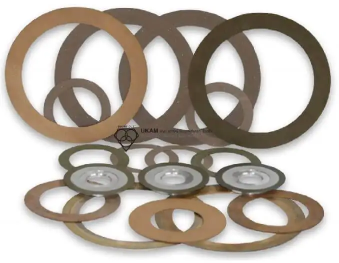
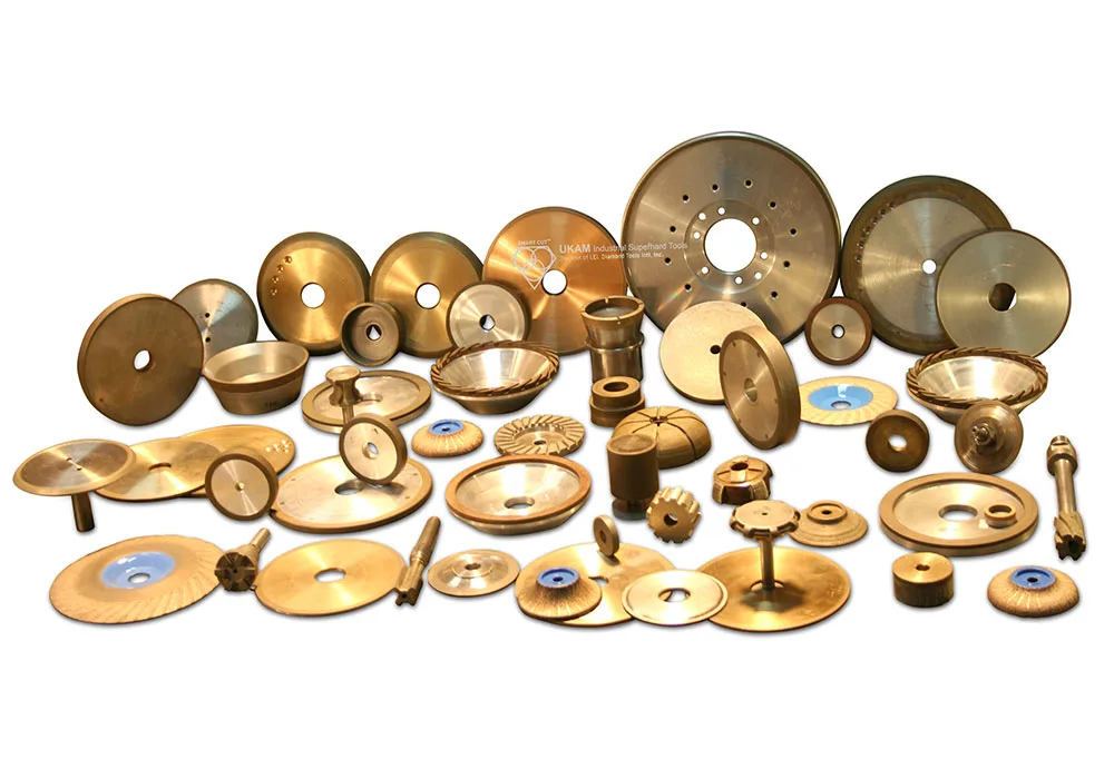
UKAM SMART CUT Diamond Blade Technologies and Product Families
UKAM offers diamond blade constructions for different cutting operations and material requirements. The following table provides an application-oriented overview of selected SMART CUT product families. It is not a substitute for checking the current specification, dimensional availability and operating limits of the exact part number.
|
UKAM product family |
Published construction or application |
Engineering consideration |
|---|---|---|
|
Material |
Resin bond diamond cut-off blades and wheels |
Consider for applications where cut quality and surface finish are important |
|
SMART CUT 2020 |
Nickel bond diamond cut-off blades |
Evaluate for materials and applications where exposed diamond and free cutting action are beneficial |
|
SMART CUT 205M |
Sintered metal bond cut-off blades for hard and brittle materials |
Consider for advanced ceramics and other ultra-hard materials; verify geometry and machine compatibility |
|
SMART CUT SCH Hybrid Bond |
Hybrid bond diamond and CBN dicing blades |
Evaluate where a balance of cutting quality and usable blade life is required |
|
SMART CUT Series 4500 |
Resin bond metallographic cut-off blades |
Consider for precision sectioning and metallographic sample preparation |
Published UKAM SiC wafer dicing case study
UKAM publishes a comparison of its SMART CUT hybrid bond blade against a competitor resin bond blade for silicon carbide wafer dicing.
The published test conditions were:
|
Test parameter |
Reported condition |
|---|---|
|
Workpiece |
100 mm SiC wafer |
|
Wafer thickness |
350 µm |
|
Blade dimensions |
56 × 0.15 × 40 mm |
|
Spindle speed |
25,000 RPM |
|
Feed speed |
4 mm/s |
|
Cut depth |
Full cut |
Reported results:
|
Performance measure |
Competitor resin bond |
SMART CUT hybrid bond |
|---|---|---|
|
Frontside chipping |
25 µm |
18 µm |
|
Backside chipping |
32 µm |
24 µm |
|
Reported blade life |
Approximately 800 m |
Approximately 2,100 m |
Under the reported test conditions, the hybrid blade showed lower measured chipping and approximately 2.6 times the reported blade life. These results apply to the published test setup. They should not be treated as guaranteed results for other SiC grades, machines, blade dimensions or operating conditions.
For further technical evaluation, review the UKAM dicing blade case studies.
Relevant UKAM product information:
Diamond Blade Qualification Checklist
Use this checklist before approving a new blade specification for production.
Workpiece and application
- Exact material grade and composition recorded
- Workpiece thickness and geometry confirmed
- Cutting operation clearly defined
- Material condition and orientation documented
Blade specification
- Bond type selected for the application
- Diamond grit and concentration confirmed
- Outside diameter and thickness verified
- Arbor size and mounting arrangement checked
- Maximum rated RPM confirmed
- Blade runout and dimensional tolerances reviewed
Machine and process
- Spindle and flange condition inspected
- Feed rate and RPM documented
- Coolant type and delivery verified
- Workpiece support and fixturing validated
- Dressing procedure defined where applicable
Quality and economics
- Kerf width measured
- Edge chipping inspected
- Surface finish evaluated
- Subsurface damage assessed where required
- Usable blade life recorded
- Dressing frequency recorded
- Scrap rate and cycle time measured
- Cost per accepted component calculated
Frequently Asked Questions
Start with the exact material grade, cutting operation and required edge quality. Then evaluate bond type, diamond grit, concentration, blade thickness and machine compatibility. The final specification should be confirmed through controlled cutting trials. Material name alone is not enough to determine the correct blade.
Resin bond blades use a resin matrix to retain diamond abrasive and are commonly selected when cut quality and surface finish are important. Sintered metal bond blades retain diamond throughout a metal matrix and can provide multiple abrasive layers and dimensional stability. Their actual performance depends on bond formulation, grit, concentration and operating conditions.
Electroplated blades use a nickel bond to retain exposed diamond particles, commonly in a single abrasive layer. They can provide a free cutting action and are useful in selected precision cutting and sectioning applications. Their suitability depends on the workpiece material, required finish, usable abrasive layer and blade geometry.
Not automatically. Fine grit can support improved surface quality and reduced chipping, but the result also depends on bond behaviour, concentration, cutting force, feed, coolant and machine stability. A fine grit blade that loads or cuts inefficiently may produce a worse overall process result than a correctly matched alternative.
Blade thickness influences kerf width and lateral stiffness. A thinner blade can reduce material loss, which is valuable when processing expensive materials or narrow wafer streets. However, insufficient stiffness or excessive runout can cause blade deflection and inconsistent kerf width. Select thickness by balancing material savings with machine and process stability.
First identify the actual wear mechanism. Check whether the blade is glazing, loading, losing abrasive, overheating or operating under excessive force. Review feed, RPM, coolant delivery, dressing, workpiece support and machine runout before changing the blade. A different bond or concentration may help, but the cause should be established through measured trials.
There is no single parameter that determines performance. SiC is extremely hard and abrasive, so bond wear behaviour, diamond exposure, grit, feed stability, coolant and machine rigidity all matter. Edge chipping and blade life should be measured together during qualification.
Use the same material grade, machine, cutting geometry, coolant, inspection method and acceptance criteria. Record cutting time, blade life, dressing frequency, kerf, edge damage and scrap rate. Compare the total cost per accepted component rather than purchase price alone.
A single specification may work across selected materials, but it should not be assumed to be optimal for all of them. Their hardness, fracture behaviour, abrasiveness and thermal response differ. Each application should be evaluated against its own quality requirements and machine conditions.
Engineering Principles for Selecting Diamond Blades
Reliable diamond blade selection is a process engineering decision, not simply a purchasing decision.
The most important principles are:
- Select the blade for the actual material grade and cutting operation, not just the material family.
- Evaluate bond, grit, concentration and geometry as a combined specification.
- Confirm machine compatibility, runout and rated RPM before production trials.
- Measure edge quality and subsurface damage alongside cutting speed.
- Record blade life and dressing frequency under repeatable conditions.
- Compare suppliers using cost per accepted component.
- Validate performance under representative production conditions before approving a specification.
A technically suitable diamond blade should provide stable cutting performance, repeatable quality and an economically defensible production result.
Need Help Specifying a Diamond Blade for Your Application?
A blade recommendation is only as reliable as the application information behind it. When requesting a custom diamond blade or process recommendation, provide:
- Workpiece material and exact grade
- Cutting operation and workpiece dimensions
- Required blade diameter, thickness and arbor size
- Current blade bond, grit and concentration, if known
- Machine make and model
- Current spindle speed and feed rate
- Coolant type and delivery method
- Required kerf width, edge quality and dimensional tolerance
- Current problems, such as chipping, glazing, short tool life or excessive cycle time
- Production volume and target cost per accepted component
UKAM can use these details to evaluate the application and discuss an appropriate blade specification.
- Request a technical recommendation: UKAM Custom Diamond and CBN Tools
- Explore diamond blade technologies: UKAM Industrial Superhard Tools
Trusted by Tens of Thousands of Manufacturers, Laboratories,
Research Institutions Worldwide Since 1990
American Based Manufacturer
Established in 1990
