Wafering Blade Usage Recommendations
-
Posted by
 Carlos Sanchez

The wafering/sectioning blade itself is only a small factor in your sectioning operation. Successful wafering/sectioning operation is both an art & science. Requiring proper use and understanding of selecting the right diamond wafering/sectioning for your material / application. Find everything you need to make you a sectioning export
Share this Article with Friend or Colleague
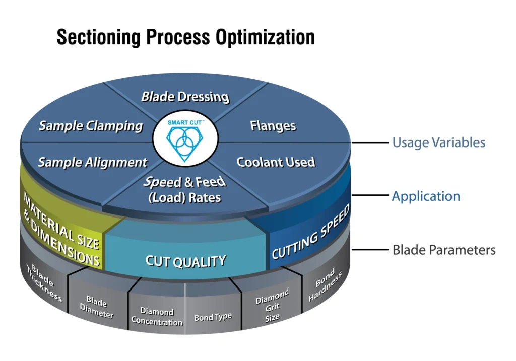
In order for you to get the most out of your wafering/sectioning blade, we strongly urge you to read and follow these instructions and suggestions. Doing so will help you save money and time. These suggestions and recommendations have come from years of experience in research, development and manufacturing of wafering/sectioning blades. As well as years of personal experience and observations of clients like you. The wafering/sectioning blade itself is only a small factor in your sectioning operation. Successful wafering/sectioning operation is both an art & science. Requiring proper use and understanding of selecting the right diamond wafering/sectioning foar your material / application. Maintaining and using proper:
Selecting the right wafering/sectioning blade parameters, often involves a trial and error process. Many which can be avoided through experience and understanding of how to use these parameter for your specific application. What works for one application, may not work for another. While there is no real substitute for experience, even new wafering/sectioning saw operators can quickly become proficient by learning and applying some basic principles of wafering/sectioning. Many parts of this guide have been published or presented in several industry magazines or presented at conventions.
Safety
Always wear proper safety equipment: Safety footwear, snug fitting clothing, safety goggles, hearing and head protection, and proper respiratory equipment. Always use blade guards provided on machines. Do not remove these safety devices. They are for your protection.
Before Using
Make sure that the arrow on wheel point in the same direction as shaft rotation. Best performance and life will result. Before performing any cutting operations, let the tool run for a few seconds without load. If blade wobbles, vibration or unusual noise occurs, stop the tool immediately. Inspect blade for damage or incorrect mounting.
Dressing is the process of sharpening & exposing diamond particles in bond matrix in order for the diamond particles to freely penetrate into the material, minimize loads, and provide good cut quality. Another reason for dressing blades is to clean a loaded blade from debris that is filling the pores between the abrasive particles. Cutting into the dressing plate creates mechanical and thermal stress and thus produces clean surface being cut.

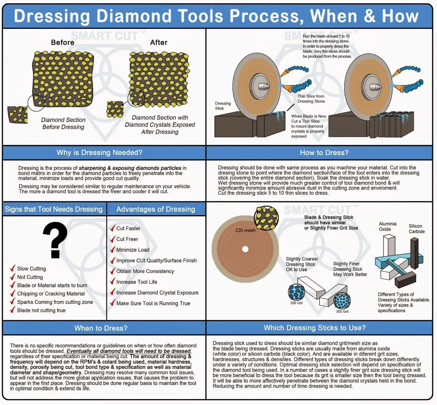
Wafering/sectioning blades that are poorly dressed will tend to push the material, creating high loads, high cutting temperature/heat, and poor cut quality. This can also cause blade breakage. Resin bond wafering/sectioning blades have a soft binder and in most cases will require minimumdressing, if any at all. Resin bond wafering/sectioning blades are typically dressed in the material being cut. This is why they are frequently called “self dressing blades”. Nickel bond and metal bond blades have a much harder binder and much more aggressive dressing is needed in order to achieve the above mentioned goals. Nickel bond wafering/sectioning blades require dressing. It is important for the diamonds to be well protruded and exposed in order to easily penetrate into the material.
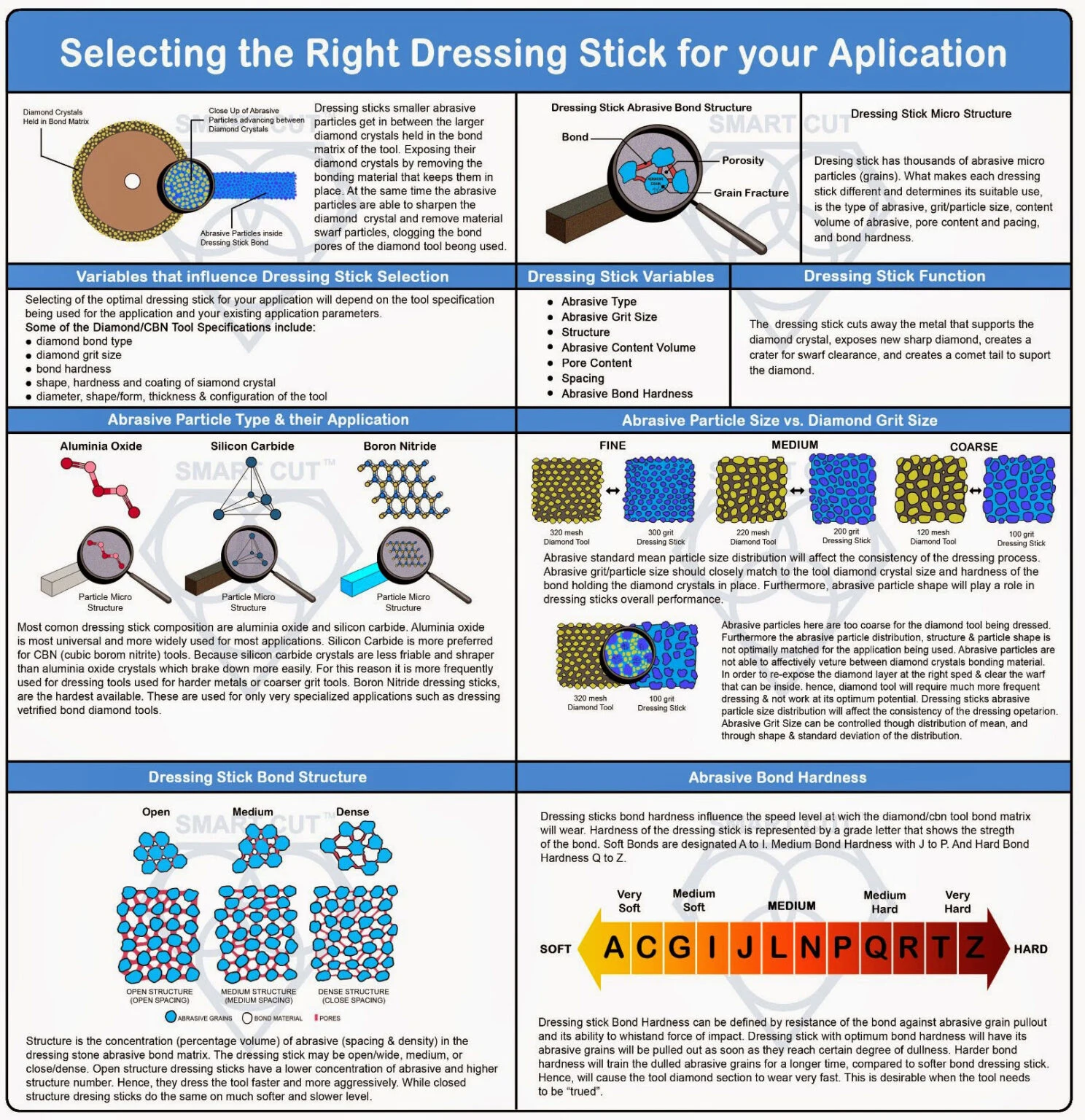
RECOMMENDED DRESSING PROCESS
Dressing procedures are established by the end user and based on experience and the application concerned. There is not one common method that applies to all applications.
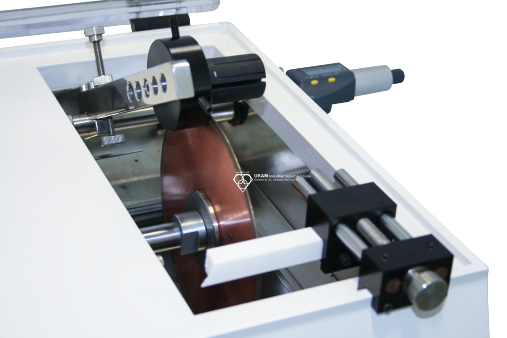
Dressing stick used to dress the blade should be same or similar diamond grit/mesh size as the wafering blade being dressed. Many sectioning saws are equipped with automatic dressing chuck that allows the user at the push of a button to forward the dressing stock slowly into the rotating blade as it is sectioning a sample. This insures the blade is continuously dressed as it cuts through the sample. This process is highly recommended especially for cutting soft and gummy samples/materials such as plastic mounted resins that typically tend to smear or gum up the blade. For best results we recommend that the dressing stock used matches the dimensions of the sample as closely as possible. When sectioning ultra hard and WORKING DURING THIS PROCESS.
dense materials such as silicon nitride, it is a good idea to implement a secondary dressing process. Dressing the blade before starting to cut the sample. Doing so will re-sharpen the diamond particles, so they are working at their maximum level of efficiency from the very beginning. This can be accomplished by making five cuts through the dressing stick, so that that the dressing stick covers the diamond section. Make sure coolant is turned on and working during this process.
When and how often should I dress my diamond wafering blade?


There are no specific recommendations or guidelines on when or how often Wafering Blade should be dressed. The sectioning saw operator should use their best judgment in determining when and how to dress the blade being used. A good rule of thum to remember: when you notice cutting rate/speed is significantly slower than when the blade was first used is a good sign the blade you are using needs to be dressed. Eventually all diamond wafering blades will need to be dressed, regardless of the material being cut. The amount of dressing a blade will require will depend on the material hardness, density, porosity being cut, as well as material diameter and shape/geometry. Dressing will re-sharpen and re-expose the diamond crystals/particles in the blade bond matrix, as well as unload the blade from material debris covering the diamond section surface. When cutting very soft and gummy materials such as plastics and some epoxy filled composites, the blade will have to be dressed more frequently than when cutting ceramics and other ultra had and brittle materials.
At same time when cutting large diameter materials where the wafering blade is taken almost to its maximum cutting capacity. For example cutting 1” (25.4mm) of material with 5” wafering blade the blade should be dressed continuously during its operation. Dong so will help prevent “build up” edge on the blade and keep the blade from binding up.
Continuously dressing sintered (metal bond) and resin bond wafering blades will not in any way reduce the life of the blade. Dressing is will most likely increase the life of the blade, avoid possible blade damage/wreckage, and optimize your sectioning operation.
COOLING
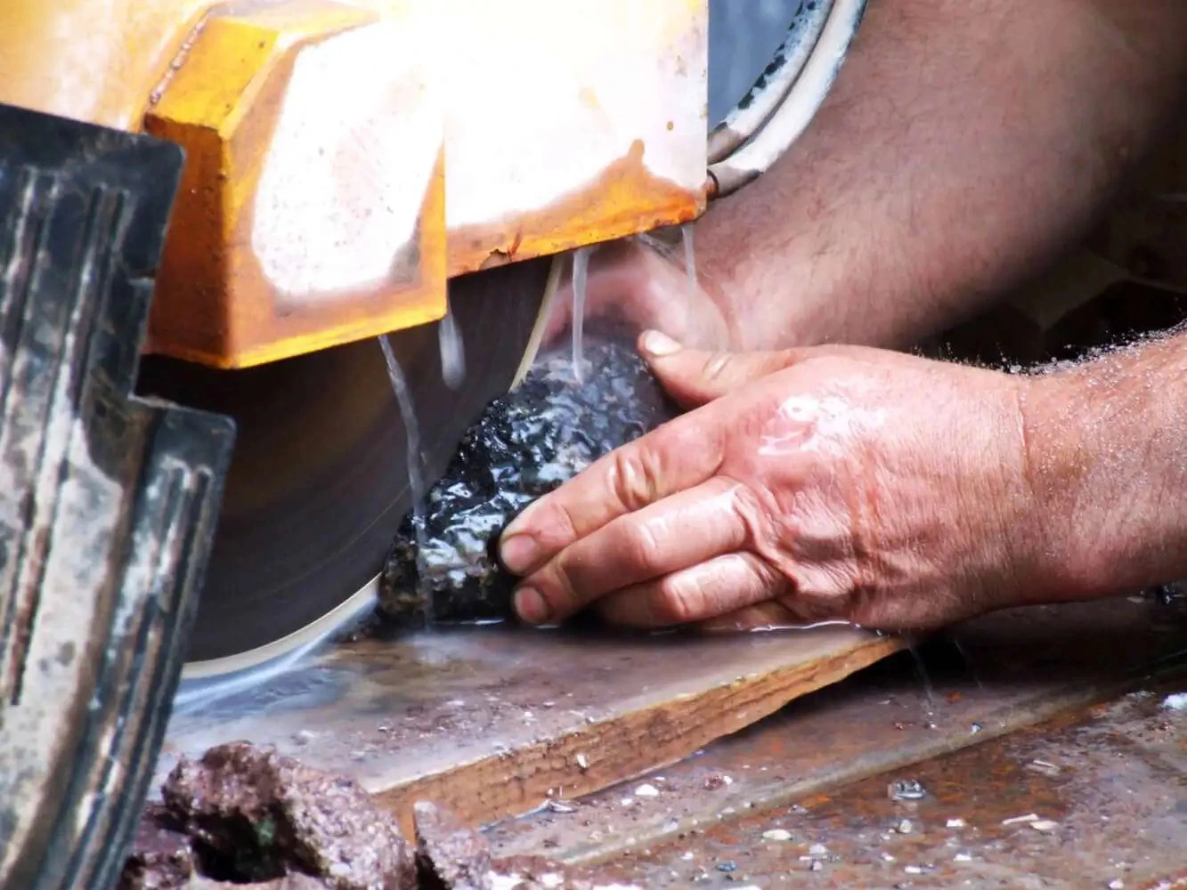
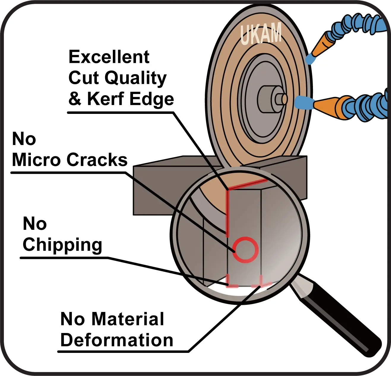
Coolant should always be used to cool and lubricate the blade. Coolant supply position and pressure is critical to minimize chipping, and maintain consistent and acceptable cut quality. Most frequent source for diamond wafering blade damage and material deformation coolant not affectively reaching the cutting zone.
Coolant serves many functions in wafering/sectioning operation:
-
 Cools blade diamond section and material being cut
-
 Provides lubrication to minimize friction between blade and material
-
 Washes out and removes powder residue and swarf from cutting process
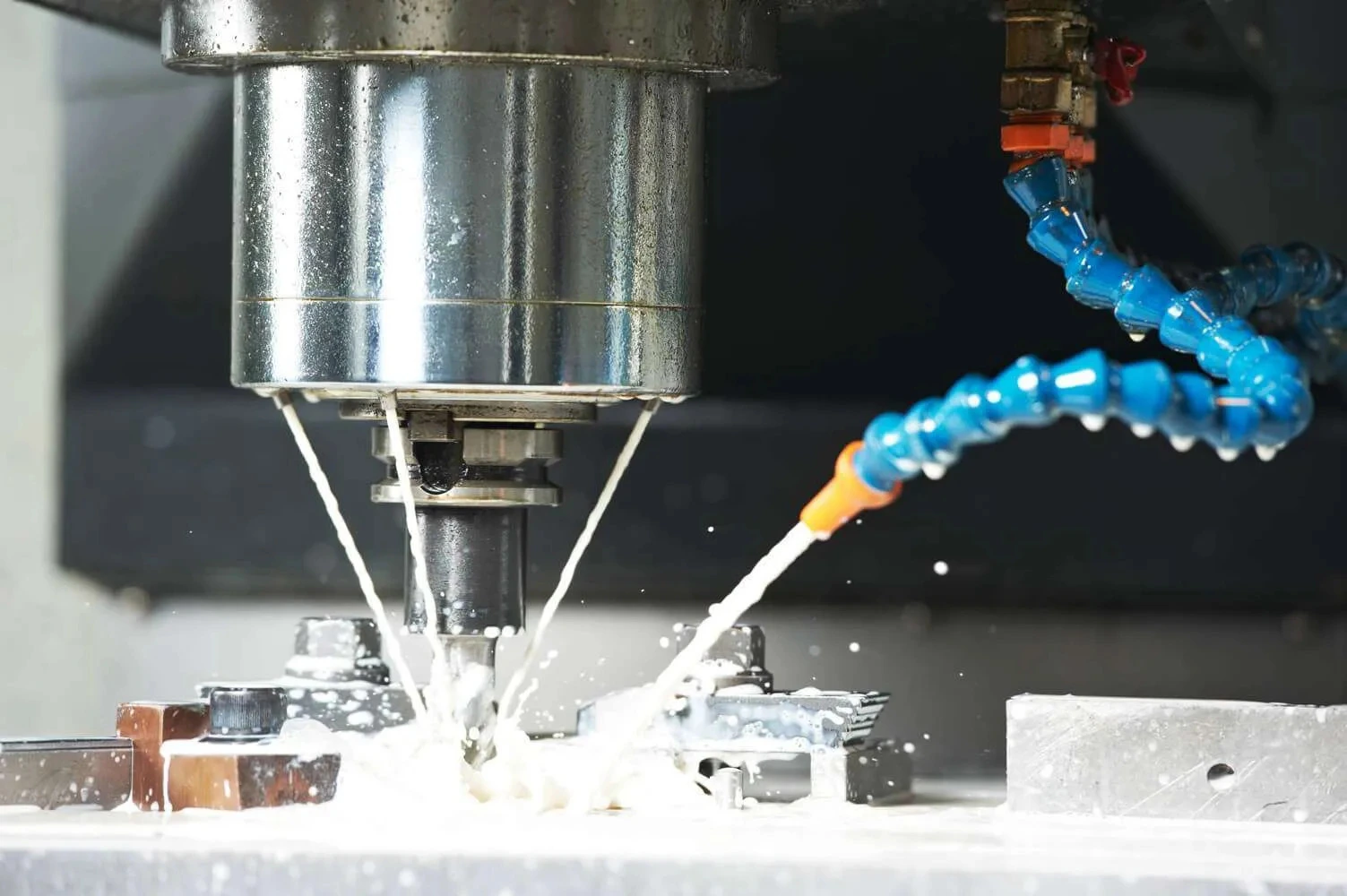
It has been found that Generous Flow of Coolant increases diamond blade efficiency, improves surface finish and reduces heat build-up and material cracks and deformation associated with overheating. Coolant must be applied in the proper place or it will not cool the blade or material being worked on properly. Coolant should always be directed so that the full flow is at the point of contact between blade and material, facing the same direction as rotation of the blade. The amount of coolant used should increase with the hardness of the material being cut. If you see sparks, there is insufficient coolant reaching the cutting zone or its simply ineffective.
Determine the type of coolant you are planning to use. Most frequently used coolant for sectioning operation are water soluable based coolant and mineral oil. Mineral oil is typically used for sectioning hard metals, where water soluable coolant is preferred on remaining family of materials.
Plain water evaporates at 212 F. Often temperature in your cutting zone reaches as much as 500 degrees F. Often water evaporates, before it has a chance of affectively cooling the wafering blade and sample being sectioned. Resulting in shorter Blade Life, Material Damage or micro cracks associated with overheating.

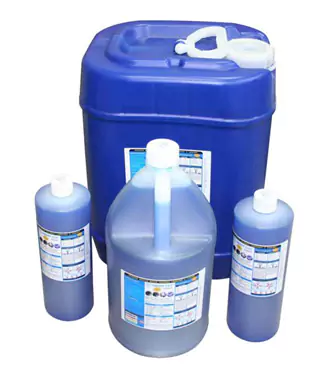
Water soluble coolant will greatly benefit your sectioning operation reducing sample/material thermal stress, edge damage, and internal cracking, assuring long-term integrity of material being sectioned. Water soluble coolant acts both as coolant and lubricant. Lubrication provided by the coolant reduces the friction between the wafering blade and material / sample. The coolant prevents the sample from sticking to the blade and will improve cut quality and minimize material deformation.
Plain water is not recommended for sectioning operation. However If you must use water as a coolant, check with the blade manufacturer on what type of water recommended for your blade. City water with 90 psi or running water is usually used for cutting. For some applications, you may want to use an additive with your coolant. If you decide to go this route, you will need a circulating system and the right ratio between your additive and coolant.
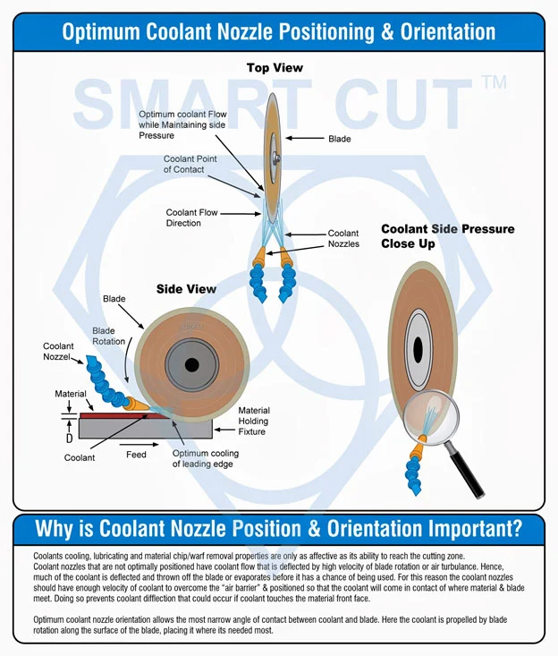
COOLANT SUPPLY TO CUTTING ZONE
However when cutting ultra hard & brittle materials the coolant flow direction and position will play a major role in determining blade life and performance.
Dual nozzle configuration is best suited to supply adequate amount of coolant at point of contact between blade and material. This type of coolant delivery configuration provides many advantages over other coolant supply methods to cutting zone. Coolant should be pointed at blade point of contact and leading edge of blade. The dual nozzle system provides two separate streams of coolant into cutting zone at angle of cutting edge of the blade. Each stream will cool one side of the blade. The nozzles should be as close as possible to the point where the blade
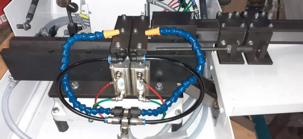
enters the material/sample. Coolant flow should blast with high velocity into the kerf to improve removing debris. wide kerfs an premature blade water is a result of improper coolant amount or flow applied at cutting zone. By correctly position the coolant stream in front of the blade, the coolant will flow on top of the material. In addition, coolant will be drawn into the kef
When cutting softer material/samples direction of cutting is not of ultimate importance. However, when cutting hard and brittle materials that are hard to section, this quiet different. The blade should enter into the material “cutting down”. As the blade penetrates the surface of the material, chips removed by diamond particles become smaller the deeper the blade penetrates. This cutting direction is most optimal to provide best cut quality and minimize material deformation.
COOLANT MAINTENANCE & OPTIMIZATION
Coolant is one of the most overlooked variables in the sectioning process. Effective and proper use of coolant and recalculating coolant system will pay off in terms of improved surface finish quality, increased blade life and more consistent cutting results. Coolant does more than just cool the blade and material, it other more important roles include: lubrication, flush away swarf particles. For most affective use of coolant the quality of water being used, coolant concentration, and maintenance of the coolant tank makes a difference. Different geographic areas have different water harnesses. Water containing less than six grains of dissolved minerals per gallon is considered soft water, water containing more then seventeen grains per gallon is considered hard. The best coolant water to use in a coolant system is chemically pure water, which is free of all dissolved solids. Chemically pure water and reverse osmosis. Reverse osmosis is the method most recommended by coolant manufacturers, however not always available. Deionized water offers much improvement over available city water.
Water in the tank can evaporate and remaining water can become harder. Hard water affects coolant capabilities in many ways decreased capability to the rust inhibitor, increased foaming, formation of a sticky residue, and increased bacteria counts. Coolant concentration should be controlled and maintained to ensure that the coolant is being used at optimum efficiency. Too little coolant in the tank will lead to corrosion and rancidity, while too high of a concentration can also cause foaming. Maintenance of the re-circulating tank is also critical to coolant performance. Cleaning he tank is a dirty job, but if done often enough and thoroughly, it can increase the performance of your sectioning saw. Keeping he coolant tank clean will ensure that you are getting the most form your coolant, keeping corrosion and bacterial growth a bay while providing the necessary coolant, lubrication and protection of your blades and material.
RECIRCULATING COOLANT SYSTEMS
Recirculating systems in the past have been used very infrequently in most laboratory environments. Today the increasing variety of work and materials sectioned by materials research and sample preparation labs are making this overlooked aspect and requirement for many applications.
Recalculating coolant systems, require filtering to remove the swarf particles created during cutting process. These coolants systems typically use either cartridge, centrifugal, or cascade. Which process to use will depend on your application. Excessive amount of swarf particles mixed in coolant will slow heat transfer of coolant and may cause surface damage to material being cut. Coolant system must be constantly controlled and monitored in order to insure process consistency
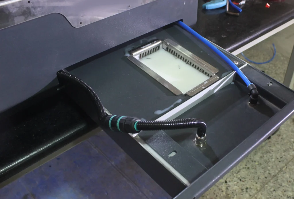
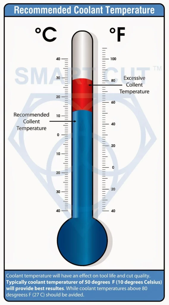
Coolant temperature will also have an affect on blade life and cut quality. Typically coolant temperatures of 50 degrees F (10 degrees Celsius) will provide best results. White coolant temperatures above 80 degrees F (27 C) should be avoided. Refrigeration of the coolant system can be used with most coolant systems and will provide best results.
Properly securing the material in place is one of the first and most important steps in the sectioning process
SAMPLE / MATERIAL CLAMPING / FIXTURING
Properly securing the material in place is one of the first and most important steps in the sectioning process. The function of the chuck or holding fixture is to keep the sample or material firmly in place, preventing it from moving during sectioning / cutting. Various sample chucks and holding fixtures are available for a wide range of sectioning saws to accommodate all types of material shapes and geometries. It is very important to use the right mounting media for your specific sample. The choice of chuck for your application will depend on the initial sample or material dimensions, desired cut depth, and material properties such as hardness, brittleness, and shape or geometry.
Using the correct chuck is crucial because improper clamping can lead to several issues. For instance, occasional chipping at the bottom of the cut can be a challenge. This problem arises when the back side of the material does not have firm support at the cutting area, creating a higher chipping rate when the blade exits the cut. Ensuring firm support throughout the material's length can help mitigate this issue.
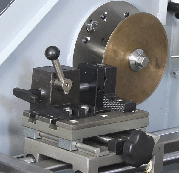
The sample must not move while being sectioned. Movement of the sample can damage the material or the blade and can prevent obtaining a planar section. However, the sample must also not be over-tightened. Over-tightening can damage the chuck or the sample itself. For example, brittle materials such as those in the glass and refractory families can fracture if over-tightened. On the other hand, harder and denser materials such as silicon carbide can cause dents in the chuck if excessive force is applied. Dents or nicks in the chuck will affect subsequent samples sectioned in the same chuck, causing damage and potential cracks.

The choice of chuck or holding fixture must account for the specific characteristics of the sample. For irregularly shaped samples, custom fixtures might be necessary to ensure even clamping pressure and stability during cutting. For cylindrical samples, v-blocks or collet chucks can provide the necessary support and alignment.
In addition to selecting the right chuck, using proper padding and cushioning materials can help protect both the sample and the chuck from damage. Padding materials such as rubber or foam can distribute clamping forces more evenly and reduce the risk of damage to brittle samples. This approach also helps to minimize the introduction of nicks and dents in the chuck, preserving its integrity and performance over time.
Effective clamping also involves considering the dynamics of the cutting process. During cutting, vibrations and forces exerted on the sample can cause movement if the clamping is not secure. Utilizing fixtures that can dampen vibrations or distribute forces more evenly can improve the stability of the sample and enhance the quality of the cut.
The position and orientation of the sample in the chuck can also influence the cut quality. Ensuring that the sample is aligned correctly with the cutting plane can help achieve more accurate and consistent sections. For materials that are prone to deformation under clamping pressure, supporting the sample at multiple points can help maintain its shape and prevent warping.
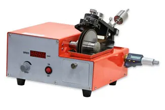
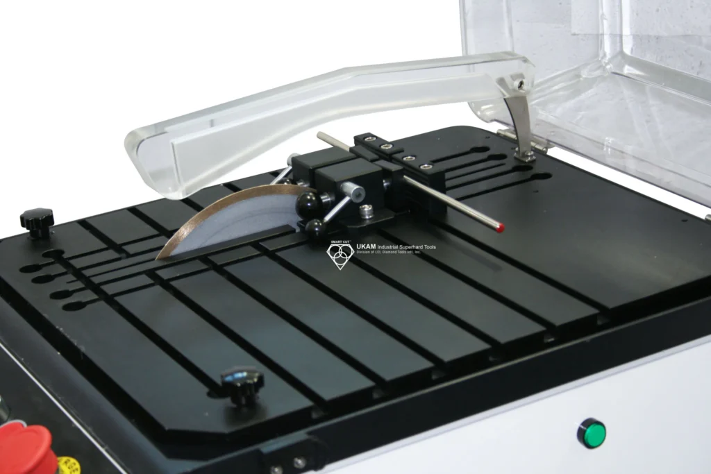
Types of chucks / holding fixtures
The choice of chuck or holding fixture must account for the specific characteristics of the sample to ensure optimal clamping and cutting performance. Different materials and geometries require tailored approaches to secure them effectively during the sectioning process. Additionally, different types of saws—low and high-speed saws, medium-speed sectioning/wafering saws, and metallographic abrasive cutters for larger diameters—require specific chucks designed for their operational characteristics.
For irregularly shaped samples, standard chucks may not provide the necessary stability and even clamping pressure. Custom fixtures might be necessary in these cases to ensure the sample is held securely without causing deformation or damage. Custom fixtures can be designed to match the unique contours and dimensions of the sample, providing a more tailored fit that enhances stability during cutting. These fixtures often include adjustable components that can adapt to different sample sizes and shapes, offering flexibility and precision.
For cylindrical samples, v-blocks or collet chucks are ideal choices as they provide the necessary support and alignment. V-blocks offer a stable base by cradling the cylindrical sample in a V-shaped groove, ensuring it remains aligned with the cutting plane. Collet chucks, on the other hand, grip the sample evenly around its circumference, distributing clamping pressure uniformly and preventing slippage during the cutting process. Both of these fixtures help maintain the sample's position and orientation, which is critical for achieving accurate and repeatable cuts.
different saw types necessitate specific chucks to ensure optimal performance, stability, and safety during the cutting process. The choice of chuck is influenced by the type of saw, the material being cut, and the specific requirements of the application.
Low-Speed Saws:
These saws are designed for delicate materials that require gentle handling to avoid damage. Chucks for low-speed saws often incorporate cushioning materials and adjustable grips to securely hold the sample without exerting excessive force. This setup is crucial for brittle materials such as ceramics, glass, and thin wafers, where even slight pressure can cause fractures or other forms of damage. The cushioning materials help distribute the clamping force evenly, protecting the integrity of both the sample and the chuck. Adjustable grips allow for precise positioning, ensuring that the sample remains stable and aligned during the cutting process.


High-Speed Saws:
High-speed saws are used for harder materials that can withstand greater forces and higher cutting speeds. Chucks for high-speed saws are typically more robust and capable of applying higher clamping forces to ensure the sample remains stable during rapid cutting. Materials like metals and dense composites are commonly processed with high-speed saws, requiring chucks that can maintain firm, consistent pressure to prevent movement and ensure precision. These chucks often feature heavy-duty construction and may include additional supports to manage the increased stress and vibrations associated with high-speed operations.
Medium-Speed Sectioning/Wafering Saws:
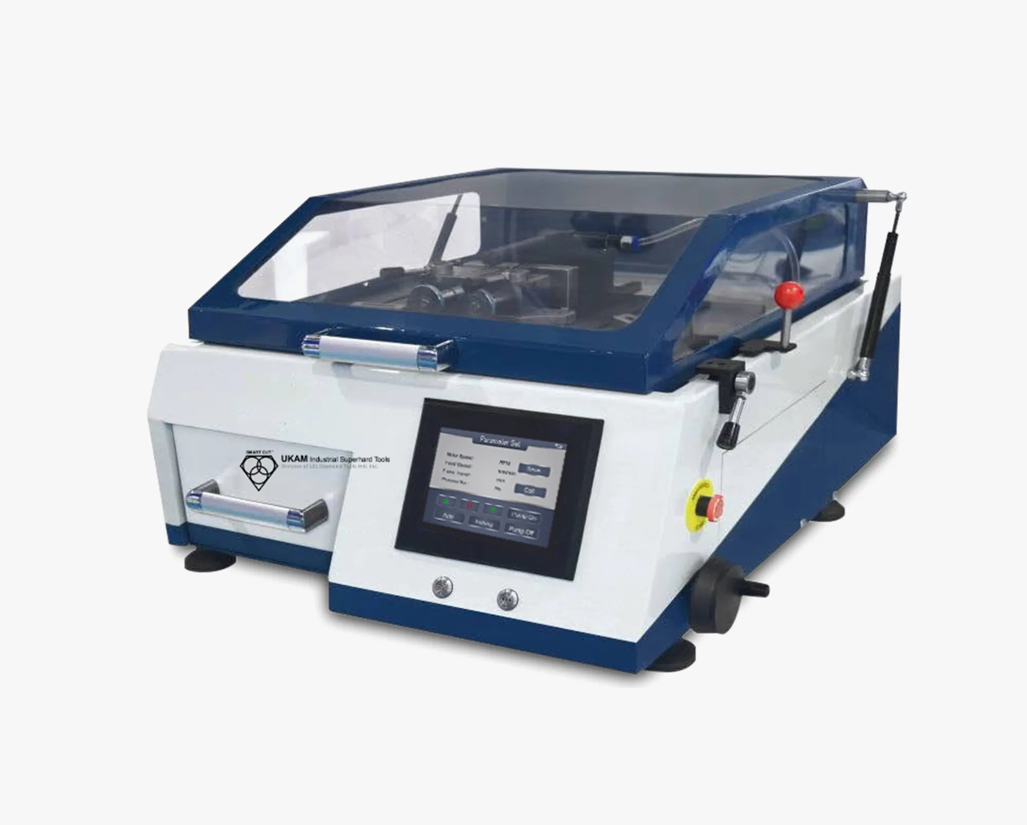
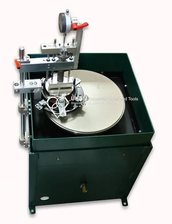
SMART CUT® 6018
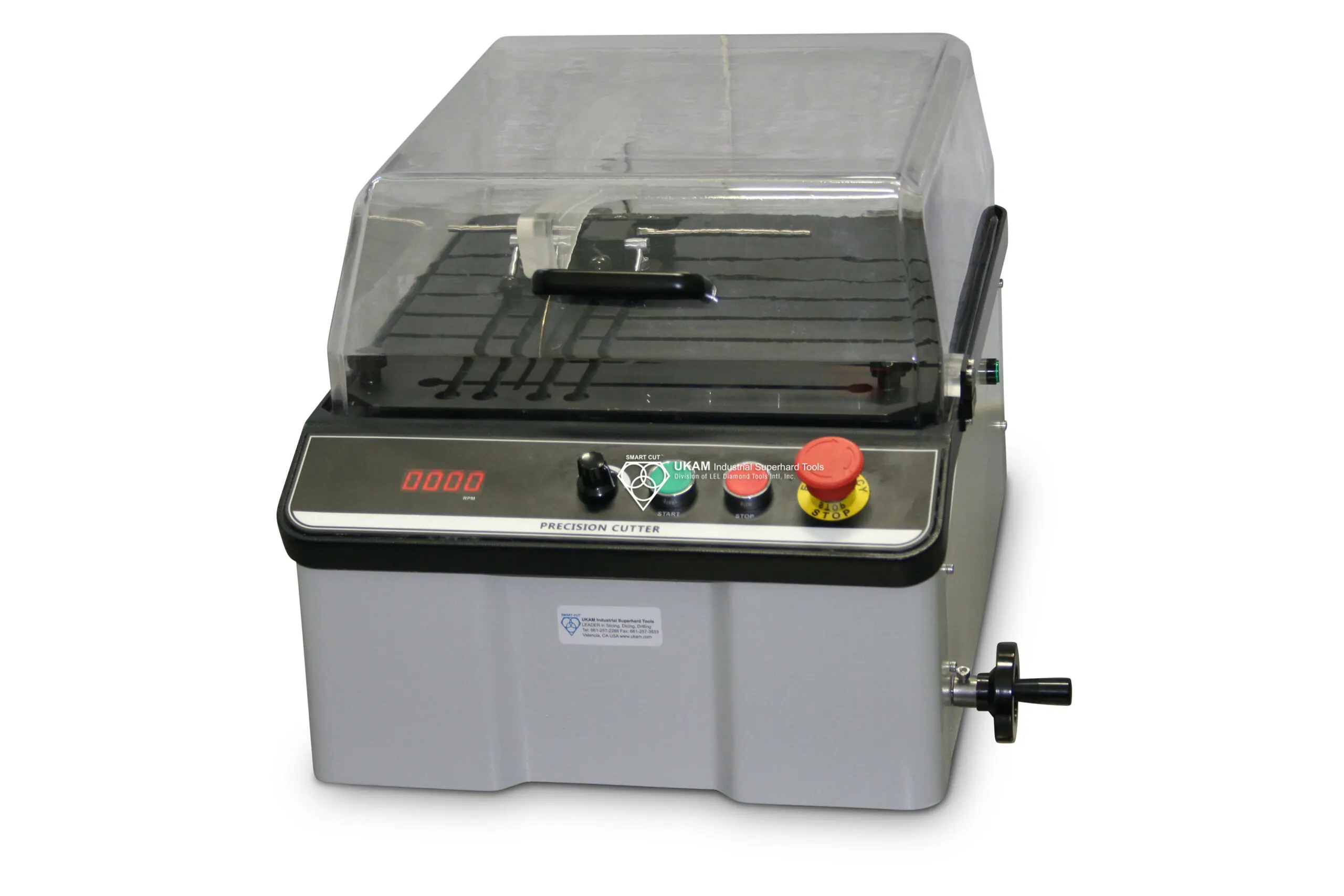
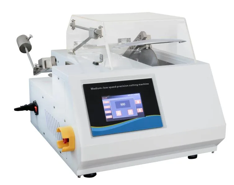
SMART CUT® 6025-Manual Low & high Speed Sectioning Saw
These versatile saws handle a wide range of materials and cutting conditions. Chucks for medium-speed saws need to be adaptable, providing secure clamping for various sample shapes and sizes. These chucks often include modular components that can be adjusted or swapped out to accommodate different materials. For example, a medium-speed saw might need to switch between holding a small, delicate sample and a larger, more robust one. The modular design allows for quick and easy adjustments, enhancing the saw's flexibility and efficiency. This adaptability is particularly useful in research and development settings, where a variety of materials and sample geometries are often encountered.

Metallographic Abrasive Cutters:
Designed for larger diameter samples, metallographic abrasive cutters typically operate at medium to high speeds. The chucks used in these machines need to handle significant forces while maintaining precise alignment. They are often equipped with heavy-duty clamps and support structures to manage the larger, heavier samples typically processed in metallographic studies. The robust construction of these chucks ensures that they can withstand the high forces generated during cutting without compromising stability or accuracy. Additionally, these chucks may feature enhanced clamping mechanisms to prevent slippage and ensure that the sample remains securely in place throughout the cutting process.
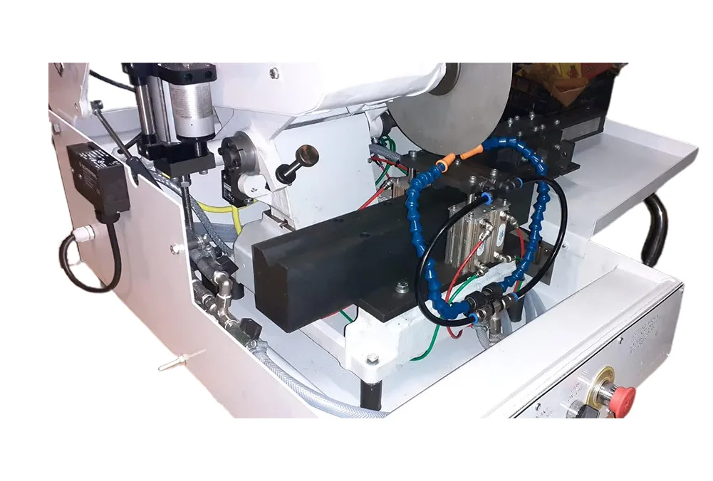
The type of padding and cushioning materials used in the chuck can also be adjusted based on the sample and saw type. Soft rubber or foam padding is ideal for delicate samples, while harder, more durable padding materials are better suited for high-speed operations and harder materials.
In addition to the sample's shape, the material's hardness and brittleness must be considered when selecting a chuck or holding fixture. Brittle materials, such as ceramics or glass, require gentle clamping to avoid inducing fractures. In these cases, fixtures with soft, cushioning materials or inserts can help distribute the pressure more evenly and reduce the risk of damage. Harder materials, like metals and dense composites, can withstand more substantial clamping forces, but it is still important to avoid excessive pressure that could deform the sample or the chuck itself.
Temperature sensitivity of the material is another critical factor. Some materials may expand or contract significantly with temperature changes, which can affect their stability in the chuck. Fixtures designed with thermal compensation features can help maintain secure clamping even as the sample's dimensions change with temperature fluctuations. These fixtures might use materials with low thermal expansion coefficients or incorporate adjustable elements that can be fine-tuned during the cutting process.
The surface finish and cleanliness of both the sample and the chuck also play a role in achieving a secure hold. Any contaminants or irregularities on the clamping surfaces can reduce friction and lead to slippage. Ensuring that both the sample and the chuck are clean and free of debris helps maintain a firm grip. In some cases, surface treatments or coatings on the chuck can enhance grip and reduce wear over time.
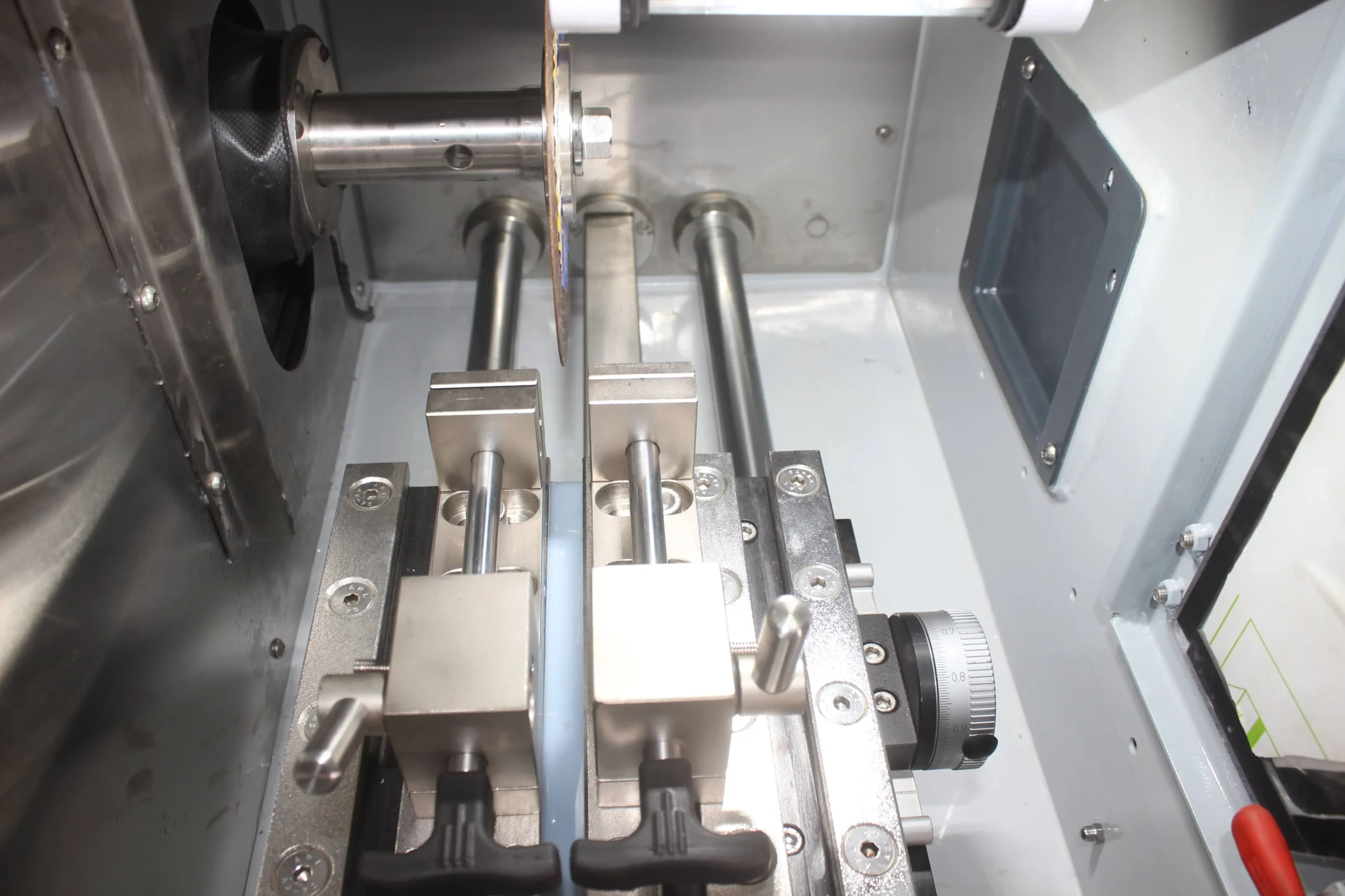
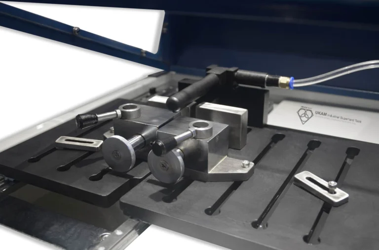
Automation and precision in clamping are increasingly important in advanced metallography and sample preparation. Automated clamping systems can provide consistent pressure and alignment, reducing variability introduced by manual adjustments. These systems often include sensors and feedback mechanisms that monitor the clamping force and make real-time adjustments to maintain optimal conditions. This level of control is especially valuable for high-throughput environments where consistency and efficiency are paramount.
Fixtures designed for quick and easy adjustment can improve workflow efficiency. Modular systems that allow for rapid swapping of different fixtures or the adjustment of clamping points can save time and reduce the risk of error. This flexibility is particularly beneficial in research settings where a wide variety of samples may need to be processed quickly and accurately.
CHUCK POSITIONING / ALIGNMENT
The positioning and alignment of the sample chuck are critical to ensuring the success of the sectioning process in metallography and sample preparation. Properly securing the sample chuck to the load arm and ensuring the correct positioning and angle of the sample can significantly impact cut quality, material deformation, and the overall efficiency of the cutting operation.
The sample chuck should be securely attached to the load arm. For most applications, this is done on the right-hand side of the load arm. However, for longer samples, mounting on the left-hand side of the load arm can provide extra clearance and minimize the possibility of the sample coming into contact with the saw hood. Improper mounting of the chuck or sample can cause damage to both the sample and the wafering blade.
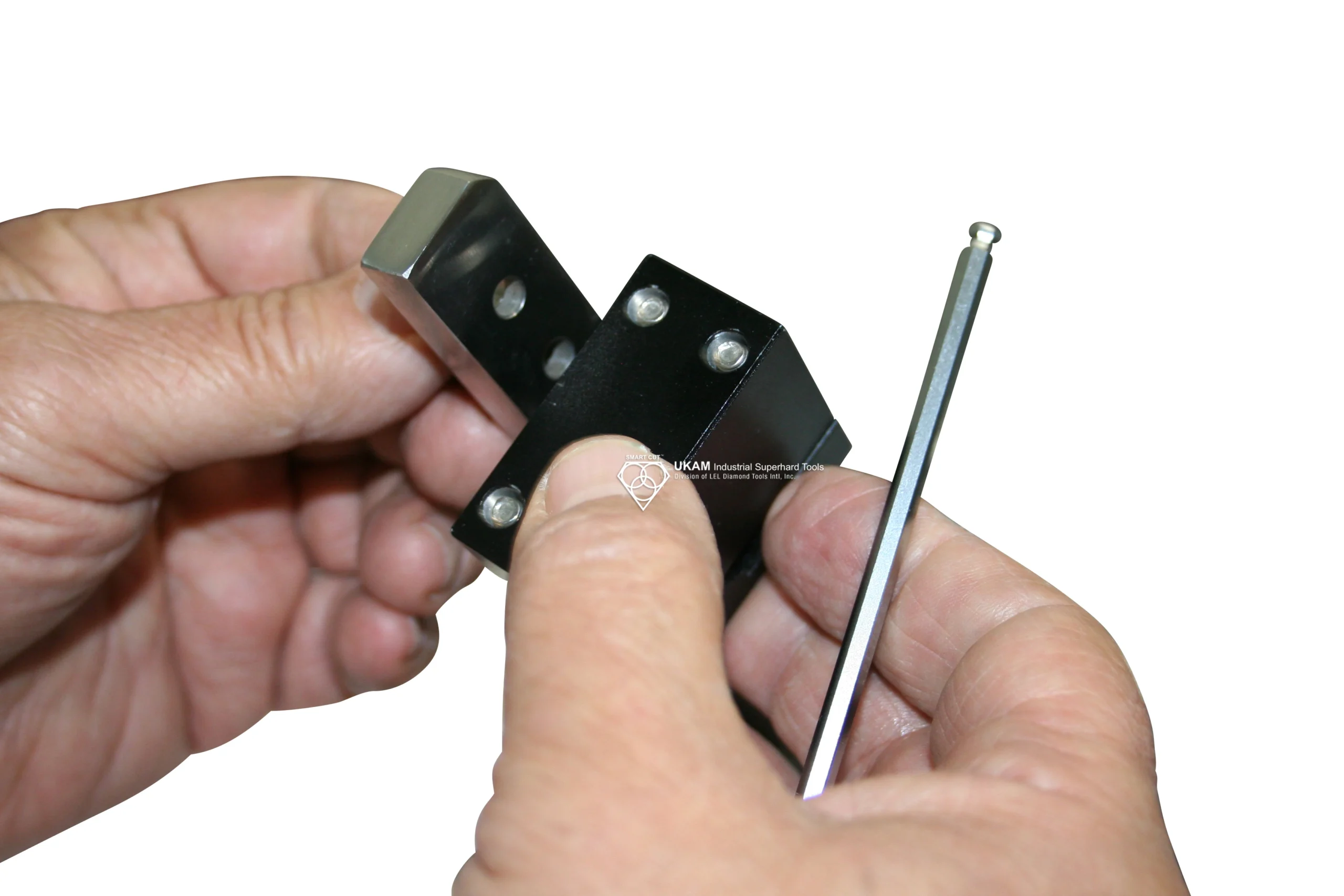
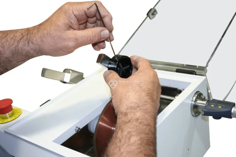
Positioning the sample and its angle where it contacts the cutting blade play an essential role in determining the cut quality and minimizing material deformation. Additionally, these factors can affect the time it takes to complete the cut or section. For optimal results, position and align the sample so that the smallest section or angle comes into contact with the blade first. This approach ensures that the sample is cut faster compared to when the widest dimension of the sample contacts the blade initially.
This alignment is especially critical for materials and samples with varying compositions and properties. For example, coated specimens should be positioned so that the coated side is cut first. This helps avoid excessive damage to the coating, which typically has different material properties than the underlying material. Cutting through the coating first reduces the risk of delamination or excessive wear on the coating, preserving the integrity of both the coating and the substrate.
Samples and materials should be aligned with the blade in a way that ensures the sample chuck does not touch the blade support flanges. During the sectioning operation, if you find that the sample chuck is touching the blade flanges, the chuck should be attached to a different position on the saw load arm. Depending on the design and configuration of your saw, this may not always be feasible. An alternative solution is to reposition the sample within the chuck to ensure there is proper clearance between the chuck and the blade flange. This adjustment helps prevent potential damage to the blade and ensures a smoother cutting process.
Proper alignment also involves ensuring that the sample is parallel to the cutting blade. Misalignment can lead to uneven cuts, increased wear on the blade, and potential damage to the sample. Use alignment tools or guides to check and adjust the sample's position before starting the cut. This practice is especially important when working with brittle or delicate materials, where even minor misalignments can lead to significant issues.
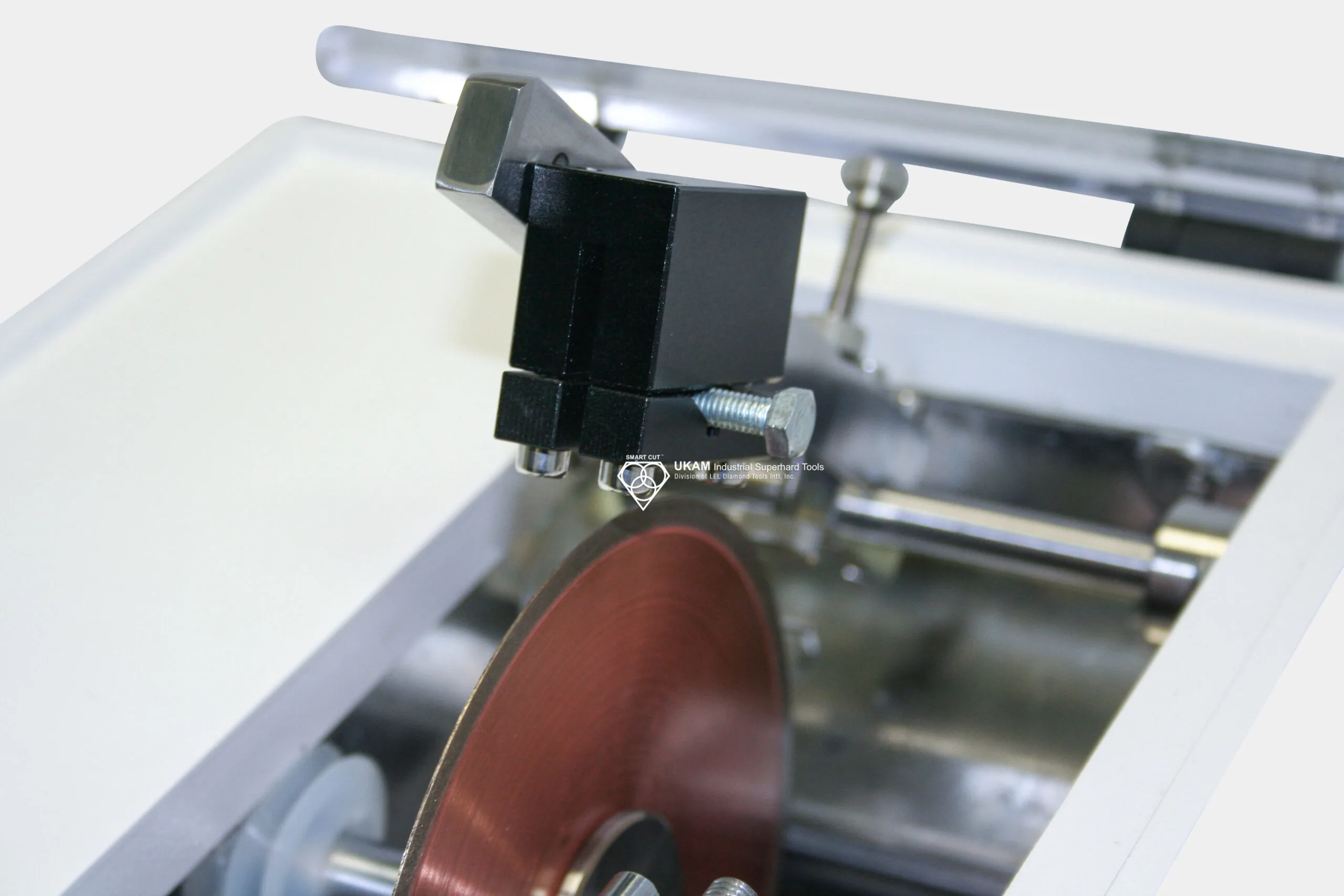
In addition to positioning and alignment, consider the force and pressure applied during the cutting process. Uniform pressure distribution across the sample helps in achieving a clean and precise cut. Adjust the load arm and chuck settings to ensure that the pressure is evenly applied and does not vary significantly during the cutting process.
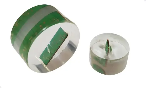
EPOXY SAMPLE MOUNTING
Epoxy sample mounting is a crucial technique for securing samples that are too small or delicate to be clamped or fixtured directly, enhancing the precision and safety of the cutting process. By stabilizing the sample within a hardened matrix, this method significantly reduces movement and vibration during cutting, which is essential for achieving clean and precise cuts, particularly with materials prone to movement or chipping.
When a sample is embedded in epoxy, it is shielded from the direct stress and potential damage of the cutting process. This protection is particularly important for fragile or brittle samples that might otherwise suffer from the physical forces of cutting. Moreover, epoxy mounting ensures that the sample can be presented consistently throughout the cutting process, which is beneficial for irregularly shaped or very small samples, providing a uniform base that facilitates easier handling and more accurate cuts.
The procedure for epoxy sample mounting involves several key steps. First, the sample and mold must be prepared by thoroughly cleaning the sample to remove any impurities that could interfere with the epoxy's adhesion. The mold should be selected to fit the sample snugly without too much excess space. Next, the epoxy resin and hardener should be mixed according to manufacturer specifications to ensure optimal performance. The mixture should be poured into the mold carefully to avoid introducing air bubbles, which can compromise the integrity of the mount.
Once the epoxy is poured, it needs to be allowed to cure fully, which can take several hours to overnight, depending on the type of epoxy used. After curing, the sample embedded in the epoxy block can be removed from the mold and mounted in the cutting machine for sectioning.
It is important to avoid air bubbles in the mixture as they can weaken the mount and affect the quality of the cut. The curing conditions should be controlled to avoid premature hardening or incomplete curing. Proper curing is essential for achieving a stable and durable mount. Safety measures should also be observed when handling epoxy resins and hardeners, using appropriate safety equipment and working in well-ventilated areas to avoid exposure to potentially harmful fumes.
BLADE MOUNTING
Flanges
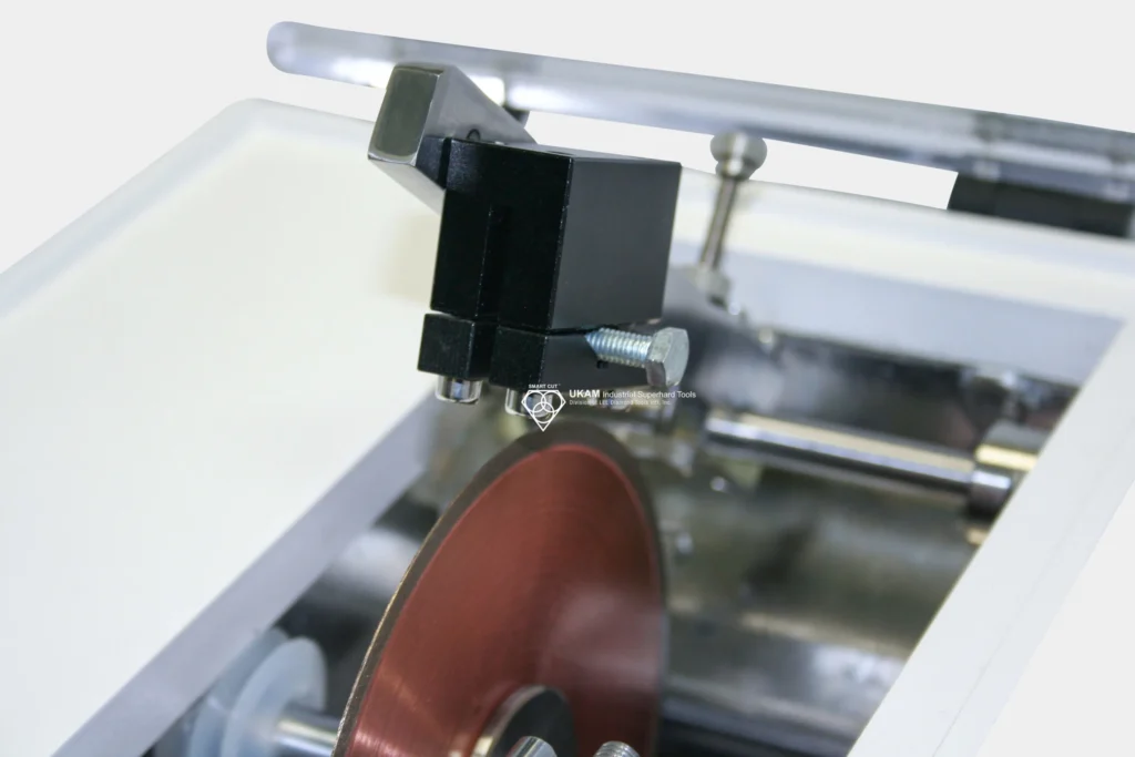
Proper blade mounting in a flange set in acceptable condition is key to any successful wafering/sectioning operation. Flanges are desined to add addition support and stability to both sides of the blade. Flanges prevent the wafering blade from warping, blade wreckage, slanting cuts, damage to material/sample and much more. Flange Diameter to use would be based on blade diameter and thickness used, material diameter/dimensions (desired exposure ration). Flange diameter affects directional stability of the diamond wafering blade. As a general rule of thumb, the largest possible flange diameter should always to be used.. Flanges shold provide sufficient clearence for sample so the cut may be completed without any interruption. For thinner and smaller diameter wafering blades, recommended flange size is ¾ of the Outside Diameter of the wafering blade.

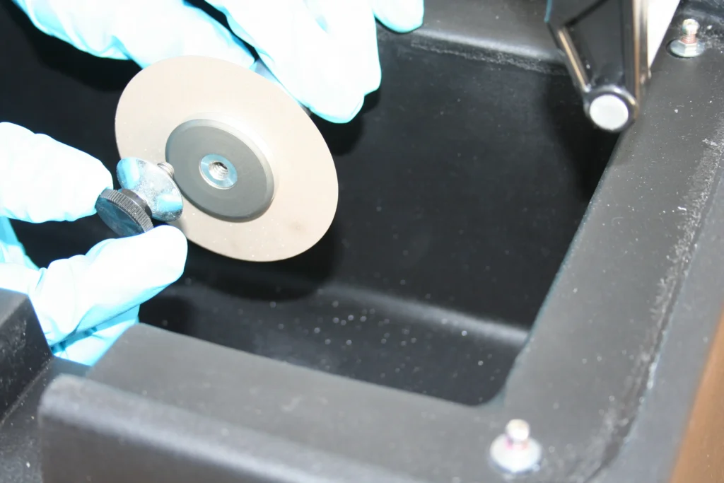
Often extending right up to the diamond section. For larger and thicker blades the recommended flange diameter is approximately 1/3 the diameter of the blade. Flanges must be free of rust and dirt. Your blade should turn perfectly true after flange nut is tightened. Carriage alignment must be accurate for deeper cuts to prevent blade bending.
Any small scratch or nick in flange edge can cause improper blade mounting. This can lead to slanted cuts, blades wobbling and wider cuts, more chipping, or even possible blade breakage.
OPTIMIZING SECTIONING PARAMETERS
When it comes to optimizing your sectioning operation. Two most important variables besides the wafering blade itself is spindle speed and load / feed rate. These two parameters will typically take presence over all others.
SPINDLE SPEED / RPM’S
Spindle speed (RPM) is a critical factor for diamond and CBN wafering blades in metallography and sample preparation. Optimal speeds vary based on the blade's outside diameter (OD), the specific application, the material being cut, and the equipment used. Achieving the correct RPM is essential as it directly impacts blade life, cut quality, and overall process efficiency.
The OD (outside diameter) of the blade significantly influences the appropriate spindle speed. Larger diameter blades generally require lower RPMs to prevent excessive heat generation, which can damage both the blade and the material. Conversely, smaller diameter blades can operate at higher RPMs, allowing for faster cutting speeds while maintaining control and precision.


Material properties also play a crucial role in determining optimal spindle speeds. Harder materials, such as advanced ceramics or hardened steels, typically require lower RPMs. This slower speed helps to reduce the risk of blade damage and ensures a finer, more controlled cut. Softer, more abrasive materials, such as certain polymers or soft metals, can often be cut at higher RPMs. The increased speed helps to clear away debris and prevents clogging, improving overall cutting efficiency.
The specific application and the capabilities of the cutting equipment further influence spindle speeds. Precision sectioning / wafering saws designed for metallography and sample preparation with variable speed controls can be particularly beneficial, allowing for precise adjustments to the RPM based on real-time observations of cut quality and blade performance.
Operating at lower spindle speeds results in a softer wafering/sectioning action. Each diamond particle grinds out a larger portion of the material, which can lead to faster blade wear but provides better control over cut quality. This approach is suitable for applications requiring high precision and minimal material deformation. Conversely, higher spindle speeds create a harder cutting action, with each diamond particle removing a smaller portion of material. This can extend the blade's lifespan and increase cutting speed but may reduce control and increase the risk of blade wreckage if not managed correctly. High RPMs are generally more effective for cutting softer, abrasive materials where rapid material removal is beneficial.
Selecting spindle speeds involves balancing several factors. For soft, abrasive materials, increasing RPMs enhances debris clearance and maintains smooth cutting action, improving cut quality and extending blade life. For hard, dense materials, decreasing RPMs minimizes the risk of blade damage and ensures a precise, controlled cut, reducing material chipping and deformation.
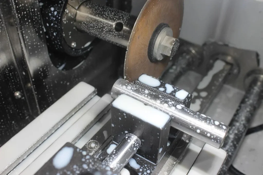
Continuous monitoring of blade performance during the cutting process is essential. Adjustments to the spindle speed should be made based on real-time observations. Signs of excessive speed, such as burn marks on the material or blade, should prompt an immediate reduction in RPM. Conversely, if the blade appears to be struggling or the cut quality is poor, a slight increase in RPM may help.
Factors that Influence Diamond & CBN Wafering Blade RPM’s
|
Factor |
Low Spindle RPMs |
High Spindle RPMs |
|---|---|---|
|
Blade Outside Diameter (OD) |
Larger blades require lower RPMs to avoid excessive heat. |
Smaller blades can operate at higher RPMs for faster cutting. |
|
Material Hardness |
Harder materials need lower RPMs to prevent blade damage and ensure precision. |
Softer materials can handle higher RPMs to clear debris and maintain smooth cutting. |
|
Material Density |
Denser materials need slower speeds to prevent excessive wear and ensure consistent cutting. |
Less dense materials can be cut at higher speeds for quicker processing. |
|
Abrasiveness |
Not specifically impacted, but higher RPMs can wear down the blade faster. |
Softer, abrasive materials benefit from higher RPMs to clear debris and reduce clogging. |
|
Effects on Blade |
Faster blade wear due to larger portion of material removal by each diamond particle. |
Increased blade longevity as each diamond particle removes smaller portions of material. |
|
Cutting Action |
Softer wafering/sectioning action, better control over cut quality. |
Harder cutting action, faster material removal but potentially less control. |
|
Applications |
Harder, denser materials needing precision and minimal chipping. |
Softer, abrasive materials where rapid removal is beneficial. |
|
General Guidelines |
Decrease RPMs for hard, dense materials. |
Increase RPMs for soft, abrasive materials. |
|
Equipment Specifications |
Ensure equipment can handle lower RPMs for larger blades and harder materials. |
Ensure equipment can achieve higher RPMs for smaller blades and softer materials. |
|
Monitoring and Adjustment |
Regularly monitor and adjust RPMs to maintain cut quality and control wear. |
Use variable speed controls to fine-tune RPM settings dynamically. |
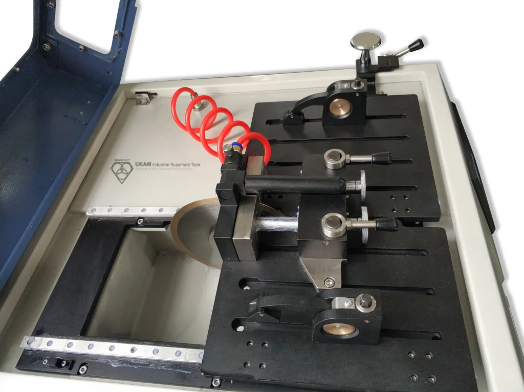
LOAD / FEED RATE
The load amount and feed rate during the cutting process are crucial factors that influence the quality of the cut, the preservation of the material's microstructure, and the longevity of the diamond & cbn wafering blade. Properly managing these parameters helps achieve the desired cut quality while minimizing deformation and damage to the sample.
Load Amount / Feed rate should be determined by your desired cut quality, material hardness, density, geometry, and thickness. The load to be applied to sample should be function of your desired cut quality and speed. Typically most loads for sectioning saws used today are between 10 to 1,000 grams.
Harder materials typically require lower feed rates and lighter loads to prevent excessive wear and damage to the blade. Denser materials may need slower feed rates to ensure a consistent and controlled cut. The shape and size of the material being cut also impact the load and feed rate. Thicker materials may require more careful handling to avoid bending or warping the blade. Most sectioning saws used today operate with loads ranging from 10 to 1,000 grams. The specific load should be adjusted based on the factors mentioned above and the specific requirements of your application.
Begin by applying light to medium pressure. Gradually feed the load arm into the rotating blade until it begins to cut at its own speed. This gradual approach helps avoid immediate stress on the blade and material. Watch for dark “burn” marks around the diamond section. These indicate that the cutting speed is too fast or that too much pressure is being applied. Excessive pressure can cause the blade to bend, warp, or even fracture, and can also result in material burning, smearing, cracks, and deformation. The load/feed rate should never be so high that the blade slows down. Ensure the blade maintains a consistent speed throughout the cutting process. When cutting completely through a sample/material and approaching the end of the cut, reduce the load/pressure on the blade. This reduction helps minimize chipping and preserves the integrity of the material as you exit the cut.

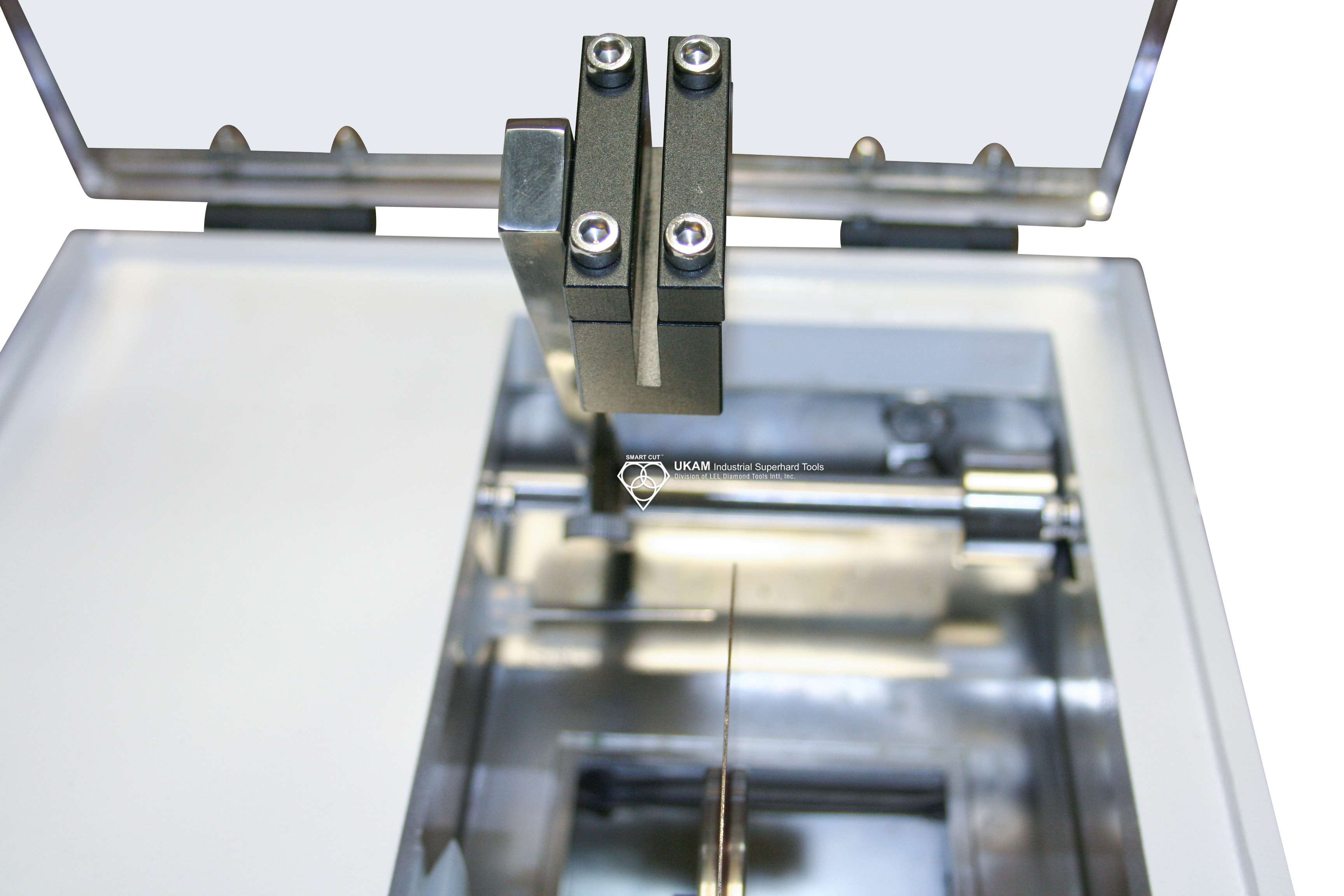
Excessive load or feed rate can cause the blade to bend or warp. This deformation not only shortens the blade's life but also compromises the quality of the cut. To avoid deformation, ensure that the load applied is within the recommended range and that the feed rate is gradual and controlled. Applying too much pressure can lead to unwanted material damage such as burning, smearing, cracks, and deformation. To prevent these issues, start with a lower load and gradually increase it while monitoring the cut quality and blade performance.
Start with light to medium pressure and gradually increase the load as the blade starts cutting. Continuously monitor the cut for signs of excessive pressure, such as burn marks or slowing of the blade. Adjust the load and feed rate dynamically based on real-time observations to maintain optimal cutting conditions. As you near the end of the cut, reduce the load to prevent chipping and preserve the material's integrity.
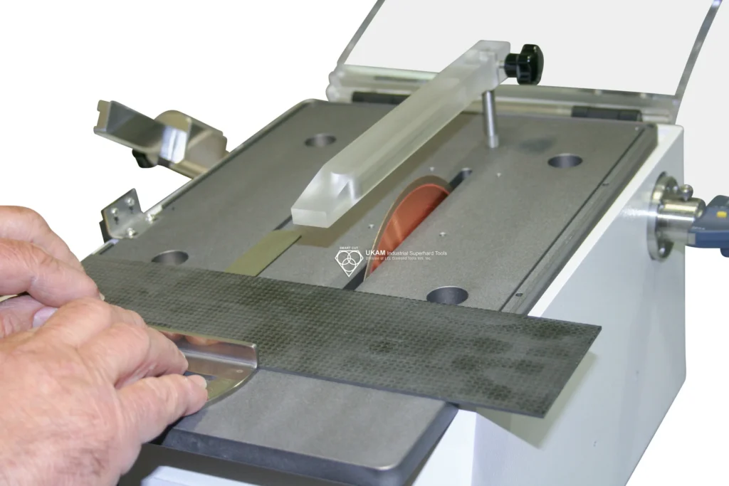
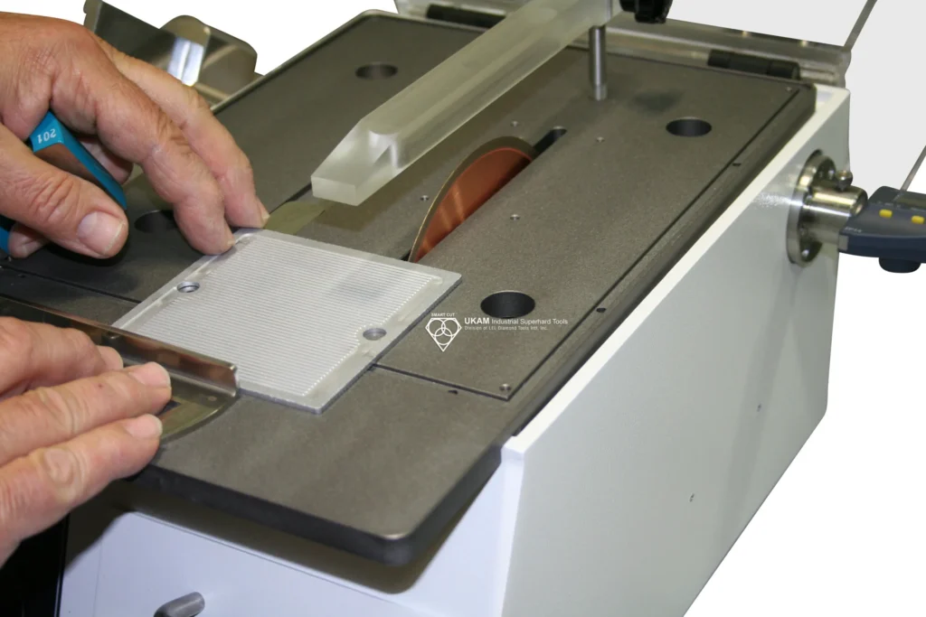
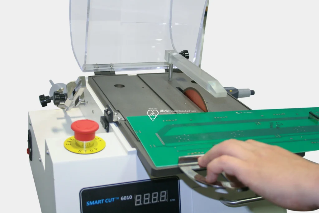
Factors that Influence Diamond & CBN Wafering Blade Load / Feed Rate
|
Aspect |
Light to Medium Load/Feed Rate |
Heavy Load/Feed Rate |
|---|---|---|
|
Desired Cut Quality |
Higher precision and better surface finish, minimal material deformation |
Potentially lower precision, risk of material deformation |
|
Material Hardness |
Suitable for harder materials to avoid excessive wear and damage to the blade |
Risky for harder materials, may cause blade damage |
|
Material Density |
Ideal for denser materials to ensure a controlled and consistent cut |
Can cause inconsistent cuts and potential blade deformation |
|
Material Geometry and Thickness |
Better for thicker materials, prevents blade bending and warping |
Can cause issues with thicker materials, including blade warping and bending |
|
Typical Load Range |
10 to 1,000 grams, adjusted based on material and desired cut quality |
Higher than recommended can lead to blade wear and material damage |
|
Initial Pressure |
Light to medium pressure, gradually increasing until the blade cuts at its own speed |
Immediate high pressure can stress the blade and material, leading to potential damage |
|
Signs of Excessive Pressure |
Few or no burn marks, blade maintains consistent speed |
Dark “burn” marks, blade slows down, indicating too fast cutting or excessive pressure |
|
Blade Performance |
Consistent blade speed, gradual feed rate |
Slowing blade speed, risk of blade bending or warping |
|
Completion of Cut |
Reduce pressure as the cut nears completion to avoid chipping and preserve material integrity |
High pressure throughout can cause chipping and compromise material integrity |
|
Avoiding Blade Deformation |
Gradual feed rate and appropriate load prevent blade bending and warping |
High load/feed rate can lead to blade bending, warping, and reduced blade life |
|
Avoiding Material Damage |
Minimizes risk of burning, smearing, cracks, and deformation |
High risk of burning, smearing, cracks, and deformation |
|
Practical Guidelines |
Start with light to medium pressure, monitor and adjust dynamically, reduce pressure near completion |
Avoid high initial pressure, monitor for signs of excessive pressure, adjust to maintain blade performance |
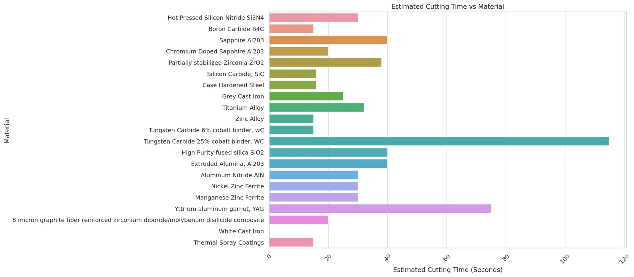
Suggested Guidelines for Sectioning of Specific Materials 0.25" (6.4mm) diameter rod. Using SMART CUT 4002 sectioning saw.
|
Material |
Blade Type |
Diamond Concentration |
Speed (RPM's) |
Load (grams) |
Estimated Cutting Time |
|---|---|---|---|---|---|
|
Hot Pressed Silicon Nitride Si3N4 |
Series 20LCU |
Low |
4,000 |
800 |
0:30 |
|
Boron Carbide B4C |
Series 20LCU |
Low |
3,500 |
700 |
0:15 |
|
Sapphire Al203 |
Series 15LCU |
Low |
1500 |
300 |
0:40 |
|
Chromium Doped Sapphire Al203 |
Series 15LCU |
Low |
500 |
500 |
0:20 |
|
Partially stabilized Zirconia ZrO2 |
Series 15LCU |
Low |
2500 |
500 |
0:38 |
|
Silicon Carbide, SiC |
Series 15LCU |
Low |
2500 |
500 |
0:16 |
|
Case Hardened Steel |
Series 15LCU |
High |
2500 |
500 |
0:16 |
|
Grey Cast Iron |
Series 15LCU |
High |
2500 |
500 |
0:25 |
|
Titanium Alloy |
Series 15HCU |
High |
2500 |
500 |
0:32 |
|
Zinc Alloy |
Series 15HCU |
High |
2500 |
800 |
0:15 |
|
Tungsten Carbide 6% cobalt binder, wC |
Series 15HCU |
High |
4500 |
900 |
0:15 |
|
Tungsten Carbide 25% cobalt binder, WC |
Series 15HCU |
High |
1500 |
300 |
1:55 |
|
High Purity fused silica SiO2 |
Series 15HCU |
High |
2500 |
500 |
0:40 |
|
Extruded Alumina, Al203 |
Series 15HCU |
High |
3000 |
600 |
0:40 |
|
Aluminum Nitride AIN |
Series 15HCU |
High |
1500 |
300 |
0:30 |
|
Nickel Zinc Ferrite |
Series 15HCU |
High |
1500 |
300 |
0:30 |
|
Manganese Zinc Ferrite
|
Series 15HCU
|
High |
2500 |
5000 |
0:30 |
|
Yttrium aluminum garnet, YAG |
Series 15HCU |
High |
3000 |
600 |
1:15 |
|
8 micron graphite fiber reinforced zirconium diboride/ molybenum disilicide composite |
Series 15HCU |
Low |
2500 |
300 |
0:20 |
|
White Cast Iron |
Series Metacut CBN |
High |
2500 |
700 |
|
|
Thermal Spray Coatings |
Series 15HCU |
High |
3000 |
700 |

ARE YOU USING RIGHT WAFERING BLADES
FOR YOUR APPLICATION?
LET US
HELP YOU
HAVING ISSUES WITH
YOUR CURRENT WAFERING BLADES?
Knowledge Center
Selecting Right Wafering Blade for your application
Wafering Blade Case Studies
Diamond & CBN Wafering Blade Performance Metrics
Understanding & Comparing Diamond & CBN Wafering Blades
Diamond & CBN Wafering Blade Guide

Carlos Sanchez is a senior technical specialist and field applications trainer with more than 17 years of experience in the use and optimization of industrial diamond tools, including ultra-thin diamond blades, core drills, and CBN grinding wheels. With a foundation in industrial engineering and technical operations, Mr. Sanchez has worked extensively with manufacturers and laboratories around the world, providing hands-on support and practical training for a wide range of cutting, grinding, and sample preparation applications.
Fluent in both English and Spanish, Carlos is known for his ability to translate complex tooling concepts into clear, actionable procedures for engineers, technicians, and production staff. His approach emphasizes real-world process improvement, tool longevity, and operator education—ensuring clients get the most out of their diamond tooling investments.
As an author, Mr. Sanchez shares field-tested insights on tool performance optimization, defect prevention, training methodologies, and troubleshooting common cutting issues.


