


Slicing and Dicing Wheels for Precision Applications: What Engineers Need to Know Before Specifying Tooling
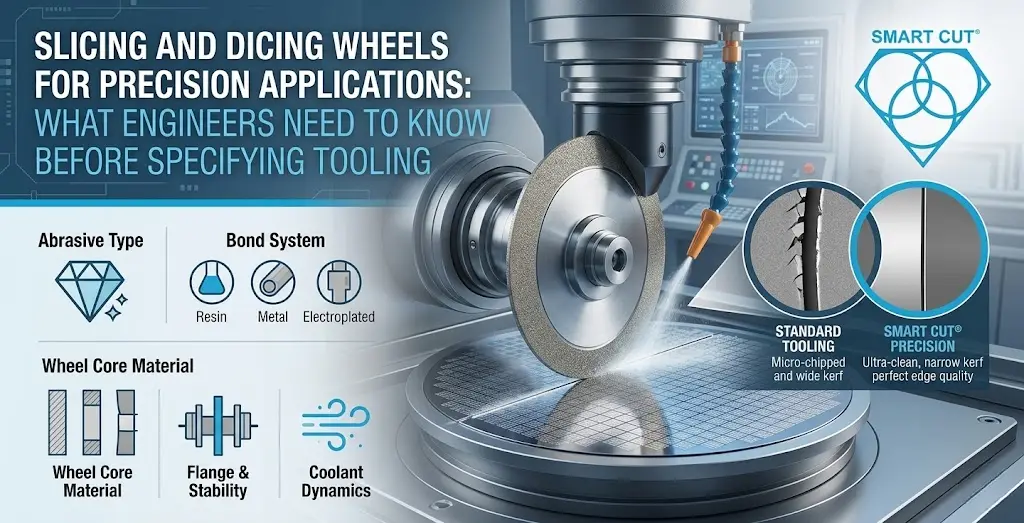
Table of Contents
ToggleWhen you’re processing silicon wafers, advanced ceramics, optical glass, or compound semiconductors, the margin for error is essentially zero. A single chipped edge, an inconsistent kerf, or a thermally damaged substrate doesn’t just mean rework — it means scrapped material, delayed production schedules, and direct cost impact on your operation.
Slicing and dicing wheels sit at the center of this challenge. The right tool performs invisibly: clean cuts, tight tolerances, repeatable results, shift after shift. The wrong tool makes itself known in the worst possible ways — mid-run, at scale.
At UKAM Industrial Superhard Tools, we’ve been engineering precision diamond and CBN tools for manufacturers, research institutions, and production environments since 1990. This article is for the engineers and process managers who need to understand not just what slicing and dicing wheels do, but what separates tools that genuinely perform from those that merely claim to.
Trusted by Tens of Thousands of Manufacturers, Laboratories Research Institutions Worldwide Since 1990
American Based Manufacturer

Established in 1990


Custom manufacturing


What "Precision" Actually Means in Slicing and Dicing Applications
Precision in cutting isn’t just about dimensional accuracy, though that matters enormously. It’s the convergence of several interdependent factors:
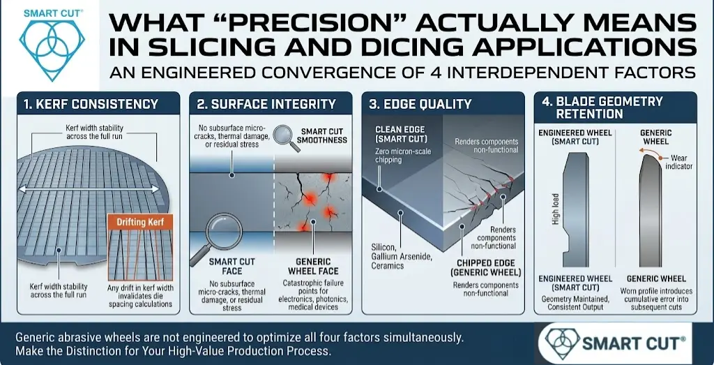
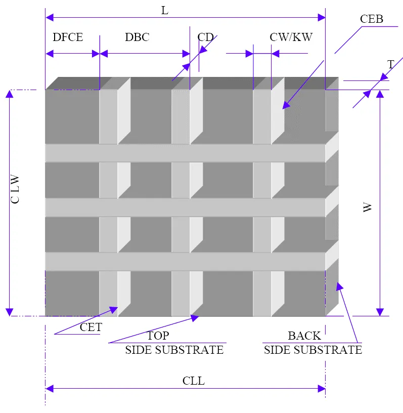
- Kerf consistency — the width of material removed per cut must remain stable across the full run, not just the first few passes. Any drift in kerf width means your die spacing calculations are no longer valid.
- Surface integrity — the cut face must be free of subsurface micro-cracks, thermal damage, and residual stress. These defects may not be visible to the naked eye, but they become catastrophic failure points in end-use applications, particularly in electronics, photonics, and medical devices.
- Edge quality — chipping at the cut edge is one of the most common and costly problems in dicing operations. For brittle materials like silicon, gallium arsenide, and advanced ceramics, even micron-scale chipping can render a component non-functional.
- Blade geometry retention — a wheel that loses its profile under load introduces cumulative error into every subsequent cut. Consistent geometry means consistent output.
Generic abrasive wheels are not engineered to optimize all four of these factors simultaneously. That’s a critical distinction for any engineer evaluating tooling for a high-value production process.
The Problem With General-Purpose Slicing Wheels in High-Precision Environments
Precision in cutting isn’t just about dimensional accuracy, though that matters enormously. It’s the convergence of several interdependent factors:
A wheel specified for “ceramics and glass” as a single category ignores the fact that alumina, zirconia, silicon carbide, quartz, and borosilicate glass have fundamentally different cutting characteristics. Hardness, fracture toughness, and thermal conductivity all vary — and the bond type, diamond concentration, and grit size that are optimal for one material will underperform or actively damage another.
Related reading: How to Select the Right Diamond Dicing Blade for Your Application | Choosing the Correct Diamond Bond Type
The result is a familiar pattern: higher wheel consumption, elevated chipping rates, more frequent dressing cycles, and inconsistent yields. These costs are real and measurable, but they tend to be absorbed into “process variance” rather than traced back to tooling specification.
Knowledge Center: Dressing Diamond Tools: Why, How, When & Where
Our Diamond Dicing Blades are engineered to address this problem directly — with specifications developed for the actual material and application, not a generic approximation of it.
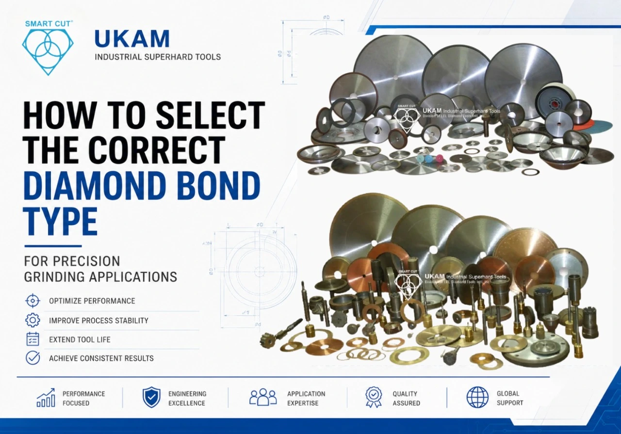
Bond Technology: Why It's the Core of the Conversation
The bond matrix — the material that holds diamond abrasive crystals in position — is the most consequential variable in slicing and dicing wheel performance. Most tooling conversations focus on diamond grit size or wheel diameter. Engineers who understand the underlying mechanics know to start with the bond.
Knowledge Center: Choosing the Correct Diamond Bond Type for Your Application
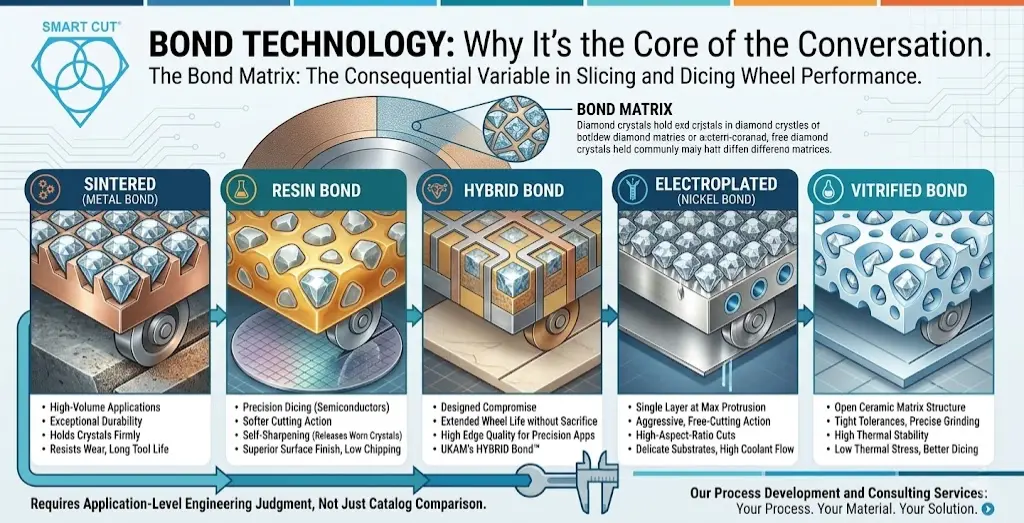
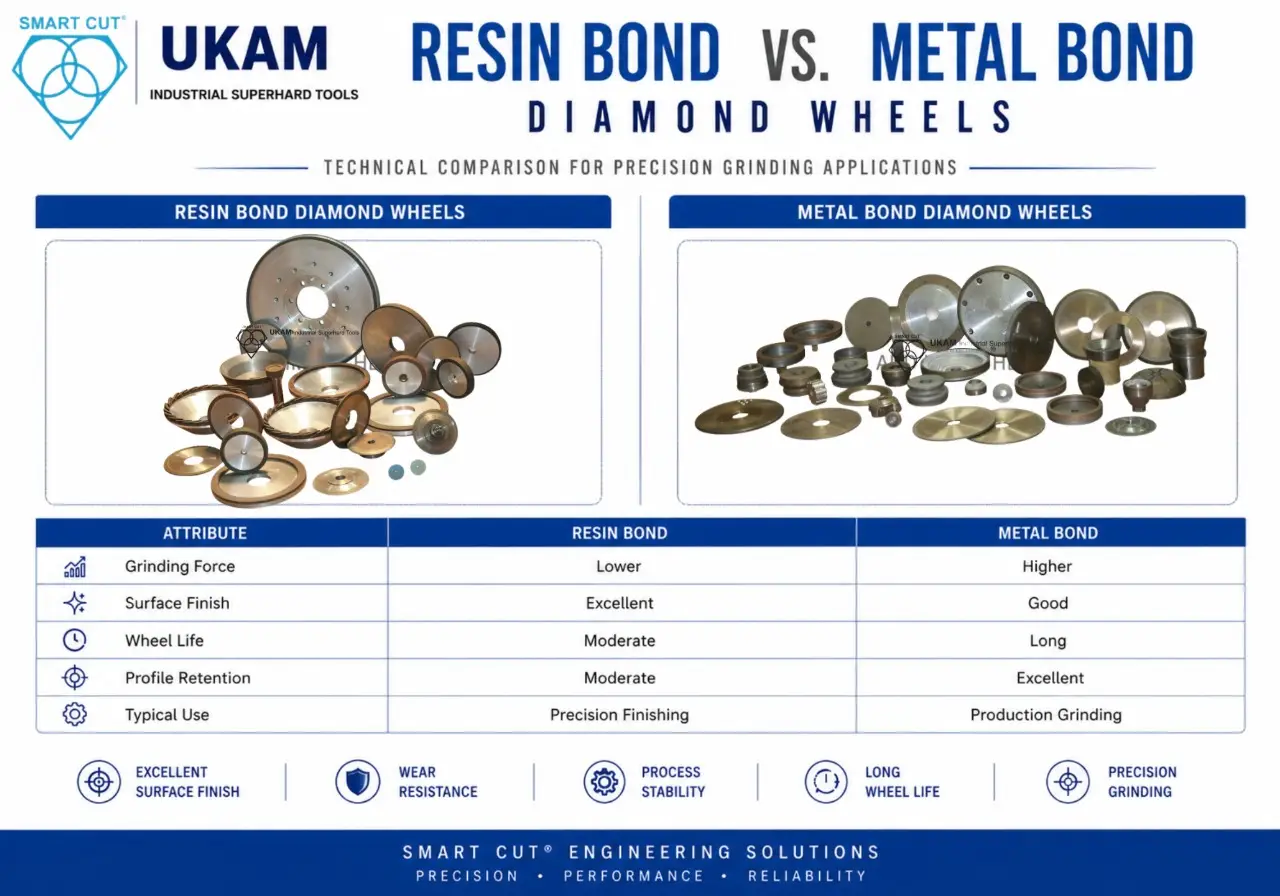
1. Sintered (Metal Bond)
tools deliver exceptional durability and are well-suited to high-volume applications on hard, abrasive materials. The bond holds crystals firmly and resists wear, making it appropriate where tool life is the primary priority. Explore our Sintered Metal Bond tools.
2. Resin Bond
tools provide a softer, more compliant cutting action. The bond releases worn crystals readily, continuously exposing fresh cutting surfaces. This makes resin bond ideal for applications where surface finish and chipping control are paramount — including precision dicing of semiconductor materials. See our Resin Bond options.
3. Hybrid Bond
technology represents a designed compromise between the durability of metal bond and the surface quality advantages of resin bond. UKAM’s HYBRID Bond™ tools are engineered to deliver extended wheel life without sacrificing the edge quality required in precision applications.
4. Electroplated (Nickel Bond)
tools place a single layer of diamond crystals at maximum protrusion — the result is an aggressive, free-cutting action with excellent coolant flow to the cutting zone. These are particularly effective for high-aspect-ratio cuts and delicate substrates. Learn more about our Electroplated Diamond tools.
5. Vitrified Bond
tools combine the open structure of a ceramic matrix with high thermal stability. They are especially well-suited to precision grinding and dicing operations where tight tolerances and thermal management are simultaneously critical. Details on Vitrified Bond technology.
Understanding which bond type belongs in your process requires knowing your material, your cutting parameters, your coolant strategy, and your quality requirements. This is not a decision that should be made by comparing catalog descriptions. It requires application-level engineering judgment — which is exactly what our process development and consulting services are designed to provide.
SMART CUT® Technology: Engineered for Consistent Performance
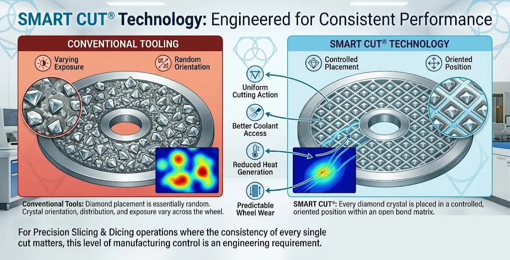
One of the distinguishing elements of UKAM’s approach to slicing and dicing tools is our proprietary SMART CUT® technology. In conventional diamond tool manufacturing, crystal placement within the bond matrix is essentially random. Crystal orientation, distribution, and exposure vary from one section of the wheel to the next.
SMART CUT® addresses this by placing every diamond crystal in a controlled, oriented position within an open bond matrix. The practical result is more uniform cutting action, better coolant access to the cutting zone, reduced heat generation, and more predictable wheel wear.
For precision slicing and dicing operations, where the consistency of every single cut matters, this level of manufacturing control is not a marketing differentiator — it’s an engineering requirement.
Knowledge Center: Key Variables in Diamond & CBN Tool Performance That Affect Your ROI | Diamond & CBN Wafering Blade Guide
Industry Applications: Where Precision Slicing and Dicing Is Non-Negotiable
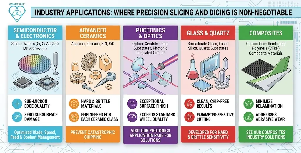
The demands on slicing and dicing tools are not uniform across industries. Here’s how the requirements differ in environments we specifically serve:
Precision in cutting isn’t just about dimensional accuracy, though that matters enormously. It’s the convergence of several interdependent factors:
1. Semiconductor and Electronics Manufacturing —
Silicon wafers, compound semiconductors (GaAs, InP, SiC), and MEMS devices require dicing with sub-micron edge quality and zero subsurface damage. Blade selection, spindle speed, feed rate, and coolant management must all be precisely matched. Our Semiconductor Industry tooling and applications expertise is built around these requirements.
2. Advanced Ceramics —
Alumina, zirconia, silicon nitride, and silicon carbide are widely used in electronics packaging, aerospace components, and medical implants. These materials are hard and brittle, and improper tooling selection results in catastrophic chipping. Our Advanced Ceramics tool offerings are engineered for each specific ceramic class.
3. Photonics and Optics —
Precision slicing of optical crystals, laser substrates, and photonic integrated circuits demands surface finish quality that goes far beyond what standard slicing wheels can achieve. Visit our Photonics application page for relevant tooling solutions.
4. Glass and Quartz —
Borosilicate glass, fused silica, and quartz substrates are used extensively in scientific instrumentation, display technology, and RF components. The combination of hardness and brittleness makes these materials highly sensitive to cutting parameters. Our Glass & Quartz tooling is developed specifically for clean, chip-free results.
5. Composites —
Carbon fiber reinforced polymers and other composite materials present an entirely different cutting challenge: abrasive wear on the tool is severe, and delamination at cut edges is a persistent quality concern. See our Composites Industry solutions.
The Total Cost Perspective: What Your Tooling Is Actually Costing You
Engineers evaluating slicing and dicing wheels often compare unit prices. This is the wrong frame of reference for precision tooling decisions.
The relevant metrics are cost-per-cut, yield rate, and unplanned downtime. A wheel that costs 30% more per unit but delivers twice the blade life, reduces chipping-related rejects by 15%, and requires fewer dressing cycles will consistently outperform a cheaper alternative on total process economics.
→ Diamond & CBN Cutting Blade Performance Metrics That You Should Know
→ Total Cost of Ownership: Why It’s Important
→ Understanding Tradeoffs: Searching for the Perfect Diamond & CBN Blade
Break Down the Real Cost Drivers
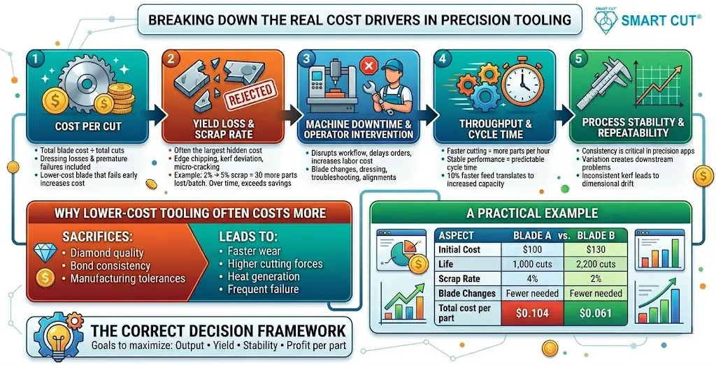
To evaluate tooling correctly, you must look at the full process impact.
1. Cost Per Cut
This is the most direct metric.
- Total blade cost ÷ total number of cuts
- Includes dressing losses and premature failures
- Accounts for actual usable life, not theoretical life
A lower-cost blade that fails early or requires frequent dressing will increase cost per cut even if the purchase price is lower.
2. Yield Loss and Scrap Rate
This is often the largest hidden cost.
- Edge chipping
- Micro-cracking
- Kerf deviation
- Surface damage
Even a small increase in reject rate has a large financial impact.
Example:
If you process 1,000 parts per batch and scrap increases from 2% to 5%, you lose 30 additional parts per batch.
Over time, this cost exceeds any savings from a lower-priced blade.
3. Machine Downtime and Operator Intervention
Every time the process stops, you lose production capacity.
- Blade changes
- Dressing cycles
- Troubleshooting poor cut quality
- Re-alignments and recalibration
Downtime is not just lost time. It disrupts workflow, delays orders, and increases labor cost.
A higher-performance blade reduces:
- Frequency of changeovers
- Process interruptions
- Operator involvement
4. Throughput and Cycle Time
Cutting speed directly impacts production output.
- Faster cutting = more parts per hour
- Stable performance = predictable cycle time
If one blade allows a 10% increase in feed rate while maintaining quality, that translates directly into increased production capacity.
5. Process Stability and Repeatability
In precision applications, consistency is critical.
- Variation in cut quality creates downstream problems
- Inconsistent kerf leads to dimensional drift
- Unstable performance increases inspection and rework
A stable blade reduces:
- Process variation
- Need for constant adjustments
- Risk of batch-to-batch inconsistency
Why Lower-Cost Tooling Often Costs More
Lower-cost tooling typically sacrifices:
- Diamond quality
- Bond consistency
- Manufacturing tolerances
- Diamond distribution uniformity
This leads to:
- Faster wear
- Higher cutting forces
- Increased heat generation
- More frequent failure
The result is higher total cost, even if the purchase price is lower.
How to Evaluate Tooling Correctly
Instead of asking:
“What is the price per blade?”
You should ask:
- How many cuts will this blade produce under my conditions?
- What is the expected cost per cut?
- How does it impact my scrap rate?
- How often will I need to stop production?
- What is the effect on throughput?
If your supplier cannot answer these questions, you are not evaluating tooling correctly.
A Practical Example
Two blades:
Blade A
- Cost: $100
- Life: 1,000 cuts
- Scrap rate: 4%
Blade B
- Cost: $130
- Life: 2,200 cuts
- Scrap rate: 2%
At first glance, Blade A appears cheaper.
In reality:
- Blade B delivers more than double the cuts
- Scrap is reduced by half
- Fewer changeovers are required
The total cost per acceptable part is significantly lower with Blade B.
The Correct Decision Framework
Precision tooling should be evaluated as a process variable, not a consumable.
- Output
- Yield
- Stability
- Profit per part
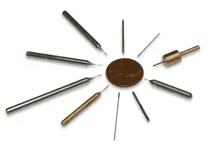
UKAM’s custom manufacturing capability exists specifically to address this. When your process has unique dimensional requirements, unusual material combinations, or atypical cutting parameters, a standard catalog tool is rarely the optimal answer. We manufacture to your specification — blade diameters from 0.5″ to 6″ (12.7mm to 154mm), thicknesses starting at 0.001″ (25 microns), and configurations built around your actual production requirements.
For operations that require consistent inventory availability, our Just-in-Time inventory and vending solutions are designed to keep precision tooling in supply without excess carrying cost.
Working With UKAM: An Engineering-First Approach
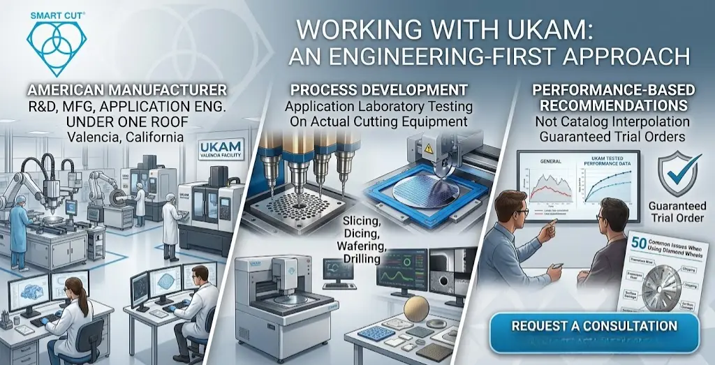
UKAM is not a distribution business. We are an American manufacturer, operating from Valencia, California, with our own R&D, manufacturing, and application engineering capabilities under one roof. When you engage with us on a slicing and dicing application, you’re working directly with the people who design and build the tools.
Our process development services include application laboratory testing with actual cutting equipment — slicing, dicing, wafering, drilling, and micro-drilling systems. When we recommend a tool specification, it’s based on tested performance data, not catalog interpolation.
We also back our recommendations with a Guaranteed Trial Order program. If a tool we recommend doesn’t perform as expected in your application, we work with you to resolve it.
For operations already experiencing problems with current tooling — inconsistent edge quality, premature wear, chipping, or surface damage — our 50 Common Issues When Using Diamond Wheels resource is a practical diagnostic starting point.
If you’re ready to discuss your specific application, request a consultation with our engineering team.
Frequently Asked Questions
- Silicon wafers, GaAs, SiC, InP, and other semiconductor substrates
- Advanced ceramics: alumina, zirconia, silicon nitride, silicon carbide
- Optical glass, fused silica, quartz
- Carbon fiber and composite materials
- Ferrite, garnet, and specialty substrates
- Metal bond: high wear resistance, best for hard abrasive materials in volume production
- Resin bond: best surface finish and chipping control, suited for semiconductor dicing
- Hybrid bond: balanced tool life and edge quality for demanding mixed requirements
- Electroplated: aggressive cutting, ideal for delicate or thin substrates
- Consult our bond selection guide or request application support
- Yes. Blade diameters from 0.5″ (12.7mm) to 6″ (154mm), thicknesses from 0.001″ (25 microns)
- Custom arbor sizes, hub configurations, and bond specifications available
- No minimum order quantity for custom tools
- Details: Custom Diamond & CBN Tools
- SMART CUT® is UKAM’s proprietary manufacturing process that controls diamond crystal placement, orientation, and distribution within the bond matrix
- Results in more consistent cutting action, lower heat generation, and more predictable wheel life
- Applicable across multiple bond types — see SMART CUT® Technology
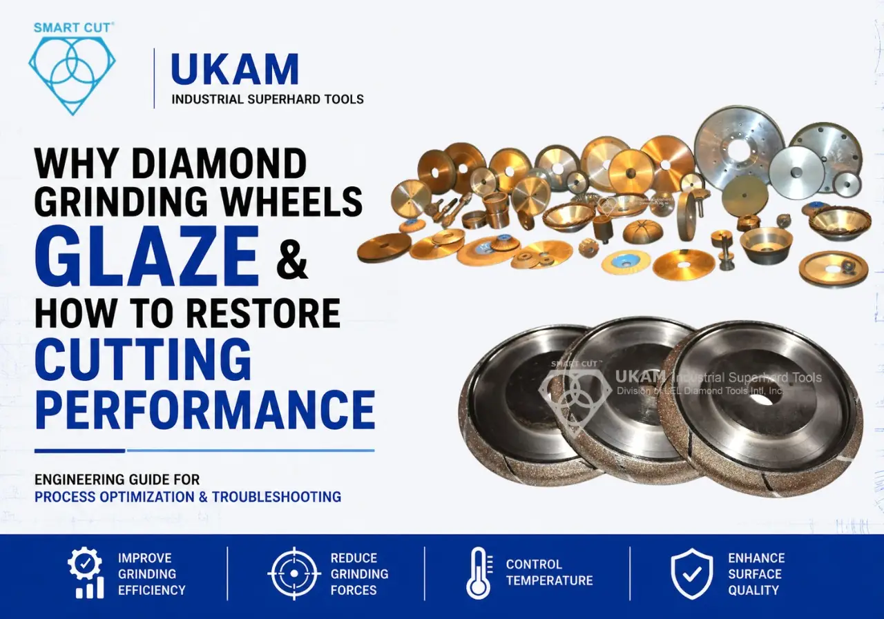
- Check grit size — too coarse a specification for the material will produce chipping
- Evaluate bond hardness — a bond that’s too hard won’t release worn crystals, causing glazing and chipping
- Review spindle speed and feed rate relative to blade specification
- Confirm coolant flow rate and direction are adequate
- Yes. Our application laboratory is equipped for slicing, dicing, wafering, drilling, and micro-drilling
- Engineers work directly with customers to develop cutting parameters and validate tool selection
- Available as a service: Consulting & Process Development
- Standard configurations typically ship same day or within short lead times
- Custom specifications vary based on complexity; fast-turn options available
- Contact us directly: Request a Quote
UKAM Industrial Superhard Tools has been an American manufacturer of high-precision diamond and CBN tools since 1990. We serve engineers, production managers, and research institutions across semiconductor, aerospace, medical, photonics, and advanced materials industries. Contact our engineering team to discuss your application.
Trusted by Tens of Thousands of Manufacturers, Laboratories,
Research Institutions Worldwide Since 1990
American Based Manufacturer
Established in 1990
Custom manufacturing
RELATED ARTICLES