


Why Diamond Core Drills Overheat — and How to Control Heat in Every Application

Table of Contents
Toggle
American Based Manufacturer

Established in 1990


Custom manufacturing


The Engineering Problem
Heat is the primary mechanism of diamond core drill failure. It softens the bond matrix, glazes the cutting face, cracks brittle workpieces, and collapses swarf evacuation, which then generates more heat. The failure is self-reinforcing once it begins.
Diamond drilling is fundamentally a grinding process. Each diamond particle abrades the workpiece at a microscopic level, and each abrasion event produces friction heat. Three mechanisms control that heat: coolant absorption and removal, hollow-core geometry reducing contact area per revolution, and swarf evacuation through the annular gap. When one mechanism fails, the other two cannot compensate. Heat accumulates. The metal bond matrix softens before the diamond degrades. Once softened, diamonds cannot cut. They rub. Rubbing generates more heat. At localized temperatures above 700°C, in dry or near-dry conditions, diamond graphitization begins and crystal loss accelerates. The bond is the first casualty in most failures. The diamond follows if the process continues uncorrected.
The financial cost is direct. Premature drill failure from heat typically produces 2 to 5 times higher tooling cost per hole, spindle downtime, and scrap rates of 15 to 30% on brittle or high-value workpieces. In optical and semiconductor environments, one thermally cracked sapphire or fused silica part can represent hundreds of dollars in material loss before rework labor or schedule impact is counted.
When Heat Control Becomes a Priority Engineering Decision

Heat control is not a routine maintenance concern. It becomes a defined engineering priority when specific production signals appear. These signals are early. Operators who wait for drill failure to diagnose process problems have already absorbed the scrap cost. If you are evaluating your tooling approach, UKAM’s application engineering team can review your parameters before failure occurs.
|
Symptom |
Most Likely Cause |
Corrective Action |
|---|---|---|
|
Rising spindle load |
Bond hardness too high for material |
Specify softer bond grad |
|
Surface burning |
Wheel glazing combined with poor coolant |
Dress wheel, improve coolant delivery |
|
Poor material removal rate |
Diamond concentration too low |
Increase concentration to 100 to 125% |
|
Elevated grinding temperature |
Inadequate coolant penetration |
Increase coolant pressure to minimum 40 bar |
|
Rapid wheel wear after dressing |
Incorrect diamond friability |
Specify tougher crystal grade |
Baseline Documentation: Parameters to Record Before Any Process Change

No process adjustment is valid without a documented baseline. Engineers who change RPM, coolant flow, and bond specification simultaneously cannot isolate which variable caused the improvement or the failure. Record these parameters before any change is made. For guidance on setting up a complete process, see UKAM’s process development services.
|
Sign of Thermal Damage |
Inspection Method |
When to Perform |
|---|---|---|
|
Surface discoloration or hazy appearance |
Visual and optical microscopy |
After every new parameter trial |
|
Subsurface micro-cracks |
Cross-section metallography |
When surface discoloration is detected |
|
Reduced cutter life in service |
Field performance tracking |
Ongoing production monitoring |
|
Surface softening |
Micro-hardness testing (Vickers) |
When thermal indicators are present |
Bond Type and Specification Selection

The relationship between bond type, diamond exposure, coolant delivery, and material characteristics plays a major role in drilling performance, tool life, heat generation, and hole quality. Understanding how to select the correct diamond bond type for your application is the most reliable way to prevent heat-related failures before they occur.
For sintered (metal bond) diamond core drills, the bond matrix gradually wears during drilling, exposing fresh diamond particles. If the bond is too hard for the material, diamond exposure may decrease, resulting in glazing, reduced cutting efficiency, increased friction, and higher cutting temperatures. If the bond is too soft, excessive bond wear may shorten tool life and reduce dimensional consistency.
For electroplated diamond core drills, diamond particles are held within a single-layer nickel matrix. Performance depends primarily on diamond quality, concentration, coolant delivery, and operating parameters — not on continuous bond wear. Unlike sintered drills, electroplated drills do not rely on bond wear to expose new layers of diamond.
Process adjustments alone cannot fully compensate for an incorrectly specified bond type, grit size, concentration, wall thickness, or coolant configuration. Selecting the correct diamond grit size and diamond concentration are equally important variables that affect cutting efficiency and heat generation.
|
Material |
Abrasiveness |
Required Bond |
Rim Geometry |
Failure Mode if Wrong |
|---|---|---|---|---|
|
Optical glass, fused silica |
Low |
Harder sintered bond, fine grit |
Continuous crown |
Premature diamond loss; edge chipping |
|
Sapphire, quartz |
Low to moderate |
Sintered fine grit, softer matrix |
Continuous crown |
Thermal fracture from micro-interrupted coolant |
|
Alumina (high purity, >99.5%) |
Low (purity reduces grit) |
Softer sintered bond |
Segmented or continuous |
Glazing due to insufficient self-dressing |
|
Alumina (standard grade) |
Moderate |
Standard sintered bond |
Segmented |
Consistent; monitor self-dressing rate |
|
Silicon carbide (SiC) |
High |
Softer bond grade |
Segmented |
Rapid wear if bond too soft for machine rigidity |
|
Silicon nitride (Si3N4) |
High |
Softer bond grade |
Segmented |
Same as SiC; monitor for rapid depth-of-cut loss |
|
Tungsten carbide |
Very high |
Metal bond, coarser grit |
Segmented |
Bond degradation at high SFM without coolant pressure |
|
Granite, hard stone |
High |
Softer sintered, segmented |
Segmented |
SFM escalation at large diameters; monitor RPM |
|
GaAs, InP (semiconductor wafers) |
Very low |
Electroplated, fine grit |
Continuous crow |
Workpiece cleave from any vibration or pressure spike |
|
CFRP / composites |
Abrasive on fibers |
Electroplated or PCD |
Specialized |
Delamination; resin softening; fiber pullout |
Step-by-Step Heat Control Process

Phase 1: Pre-Run Specification Verification
- Confirm the drill OD and calculate the target SFM using the formula: SFM = (Drill OD in inches x π x RPM) / 12. Set RPM from the SFM target, not from a generic speed recommendation.
- Verify bond hardness matches the workpiece abrasion characteristics. A softer bond for abrasive materials. A harder bond for low-abrasiveness optical and semiconductor substrates. Refer to UKAM's tool selection guide if uncertain.
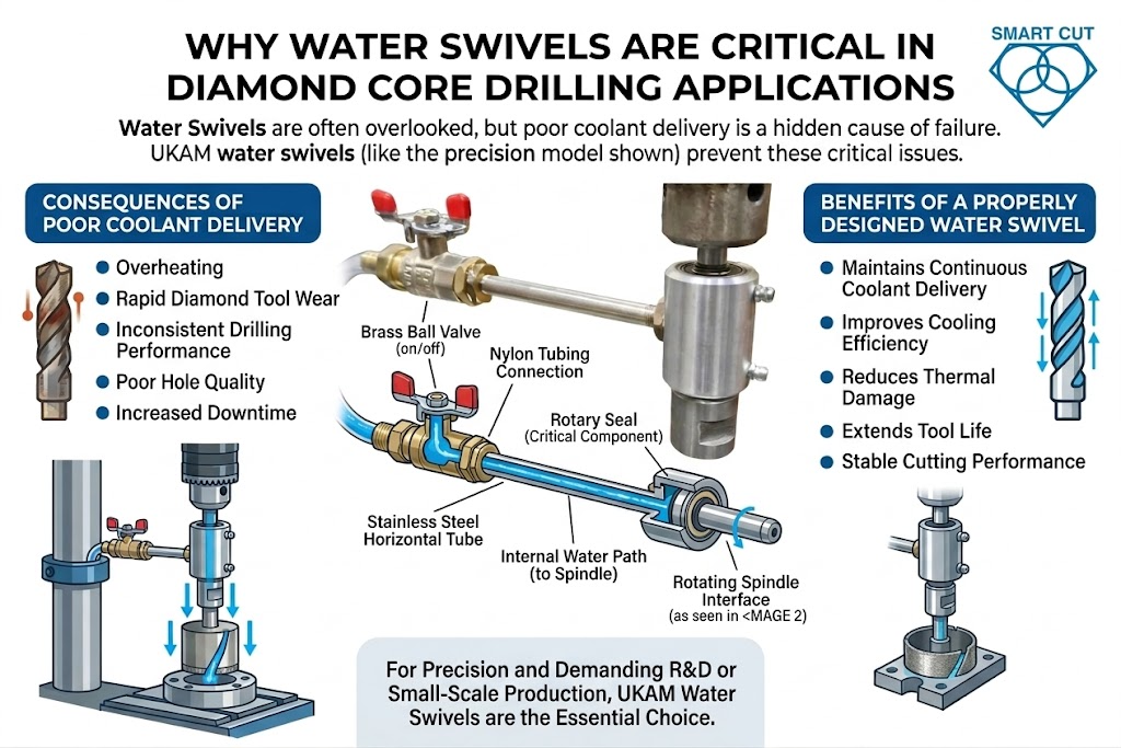
- Check coolant flow rate at the nozzle or swivel exit. Do not measure at the pump. Diamond tool accessories including water swivel adapters and coolant systems are available from UKAM.
- Confirm coolant type. Water-soluble synthetic fluid for glass and quartz applications, ceramics, and sapphire. Plain water for concrete and construction. Air blast or mist for composites to prevent delamination.
Phase 2: Drill Setup and First-Hole Qualification
- Mount the drill. Check spindle runout with a dial indicator. Runout above 0.001 inches amplifies heat generation at the cutting face, particularly in sapphire and quartz drilling where any deviation is critical.
- Establish full coolant flow before the drill contacts the workpiece. Never start dry. For continuous-rim drills on optical glass, a water dam setup provides additional protection on open-surface drilling.
- Set feed pressure to the minimum that produces forward penetration. Any pressure above that minimum is friction, not cutting. Let the diamond do the work.
- Run the first hole at the lower end of the SFM range for the material. Note cycle time, swarf color, and sound. These are your baseline indicators.
Phase 3: In-Process Monitoring
- Monitor swarf color continuously. Light gray or white swarf is correct. Dark, brown, or burned swarf is a heat signal requiring immediate parameter adjustment.
- Track cycle time per hole. An increase of more than 15% from the qualified baseline indicates glazing. Dress the drill before continuing.
- For holes deeper than 25.4 mm (1 inch), implement a peck drilling cycle. Retract the drill by 6 to 12 mm increments, allow coolant to flush the cutting zone, then resume. CNC equipment can automate this parameter.
- Do not stop coolant flow at any point during the drilling cycle. Interrupted coolant in brittle materials produces thermal cycling. In sapphire, fused silica, and optical glass, one interruption can generate invisible micro-fractures that cause part failure in service, not on the machine.
Phase 4: Post-Hole Inspection and Dressing
- Inspect the drill face after the first ten holes with a loupe or magnification. A shiny, smooth face with no visible diamond means the cutting face is glazed. Dress immediately on an aluminum oxide (AlO2) dressing stick.Diamond dressers and dressing sticks are available from UKAM.
- Log holes drilled per dress cycle from the first use of each drill. The trend over tool life reveals bond behavior and whether the specification is matched correctly to the material.
- Reduce feed pressure by 30 to 50% as the drill approaches breakthrough on the exit side. Clamp a sacrificial backing material to the exit face of the workpiece to eliminate breakout entirely.
Material-Specific Heat Control Guide
Optical Glass and Fused Silica
Thermal conductivity is very low. Heat generated at the cutting face cannot dissipate into the workpiece. It concentrates at the bond matrix and the glass surface. Three to five seconds of dry contact can produce micro-fractures in fused silica and borosilicate glass that are invisible until the part fails in service or during subsequent optical coating operations. UKAM specializes in diamond tools for the optics industry and can specify the correct drill for your exact substrate.
Specific failure mode: Subsurface radial micro-fracturing from thermal cycling. This is not visible on the surface. Parts pass visual inspection and fail during polishing or coating.
- Bond: Sintered fine grit, harder matrix grade
- SFM: 100 to 200; start at 100
- Rim: Continuous crown to minimize edge chipping
- Coolant: Flood for shallow holes; center-feed via water swivel adapter for holes exceeding one drill diameter in depth
- Prohibition: Zero coolant interruptions. No exceptions.
Sapphire and Quartz
Sapphire is the highest thermal-sensitivity material in common precision drilling. Its hardness (9 on the Mohs scale) requires aggressive diamond contact, but its thermal response to any interruption or excessive SFM is immediate cracking. Machine rigidity is a co-variable here. High spindle runout at the cutting face amplifies the heat spike with every revolution.
Specific failure mode: Conchoidal fracture from thermal shock. Unlike glass micro-fractures, sapphire failure is often catastrophic and visible immediately as workpiece cracking during or after the cut.
- Bond: Sintered fine grit, softer matrix to allow self-dressing
- SFM: 80 to 200; always start at 80
- Coolant: Center-feed mandatory at all depths. Flood coolant is insufficient for sapphire drilling at any diameter.
- Machine requirement: Spindle runout must be verified. High runout disqualifies the machine for sapphire work regardless of other parameters.
Advanced Ceramics: Alumina, Silicon Carbide, Zirconia, Silicon Nitride
These materials span a wide abrasiveness range. High-purity alumina (99.5% and above) is significantly less abrasive than standard-grade alumina. The reduction in abrasiveness reduces the workpiece-driven self-dressing rate and increases glazing risk even at correct SFM. Silicon carbide and silicon nitride are highly abrasive and self-dress the bond aggressively. For a complete overview of diamond tooling for this sector, see UKAM’s advanced ceramics industry page.
Specific failure mode for alumina: Bond glazing from insufficient self-dressing, particularly with high-purity grades. Specific failure mode for SiC and Si3N4: Rapid bond erosion producing short tool life and inconsistent hole diameter.
- Bond: Sintered metal bond; softer grades for high-purity alumina; consult engineering for SiC and Si3N4 grade selection
- SFM: 150 to 300; adjust downward for high-purity alumina
- Coolant: Flood combined with center-feed for holes exceeding one drill diameter in depth
Granite and Dense Hard Stone
Granite is self-dressing-friendly. The abrasive nature of the workpiece drives fresh diamond exposure reliably. The primary risk is SFM escalation at large diameters. A 6-inch drill at 80 RPM produces nearly 13 times more surface speed than a half-inch drill at the same RPM. Machine rigidity becomes a dominant variable at diameters above 6 inches. See UKAM’s diamond tools for stone industry for full product options.
Specific failure mode: Thermal accumulation at the cutting periphery of large-diameter drills from excessive RPM. Bond degradation in large-diameter tools happens faster than operators expect because the SFM impact of even modest RPM is large.
- Bond: Softer sintered, segmented geometry
- SFM: 150 to 300; apply the SFM-to-RPM conversion formula per diameter before setting any speed
- Coolant: Core flushing preferred for large-diameter tools; monitor flow volume at the cutting face
GaAs and InP Semiconductor Wafers
Compound semiconductor wafers cleave. Any vibration, pressure spike, or thermal event produces crystallographic fracture. Electroplated tools with fine grit are required. Cycle force must be minimized to the threshold of penetration. For full tooling guidance for this sector, see UKAM’s semiconductor industry solutions.
Specific failure mode: Cleavage fracture propagating from the hole entry along crystallographic planes. This is not a heat failure in the traditional sense but a mechanical-thermal combined failure driven by any parameter exceedance.
- Bond: Electroplated fine grit only
- SFM: Consult UKAM engineering. Standard tables do not apply.
- Coolant: Flood with low-pressure delivery; high-pressure coolant can fracture wafer-thickness stock
CFRP and Composite Materials
CFRP drilling is categorically different from brittle material drilling. Heat is still a concern, but the dominant failure mechanisms are delamination at the fiber-resin interface, fiber pullout at the hole exit, and resin softening from sustained contact temperatures above approximately 180°C. Water-based coolant accelerates delamination in certain lay-ups and matrix systems. Air blast or fine mist is the standard coolant method. UKAM’s composites industry page covers tooling options in detail.
Specific failure mode: Interlaminar delamination at the hole exit face, driven by feed pressure and inadequate backing material. Heat-induced resin softening produces fuzzing on hole walls.
- Bond: Electroplated or PCD (polycrystalline diamond)
- SFM: 200 to 500; composites tolerate higher speeds but require delamination monitoring
- Coolant: Air blast or fine mist. Confirm compatibility with specific matrix system before using water-based coolant.
Supplier Evaluation Table

Use the following questions when qualifying a diamond core drill supplier. The answers reveal process knowledge, manufacturing consistency, and whether the supplier can support your specific application. UKAM has provided application engineering support to manufacturers, laboratories, and research institutions since 1990.
SMART CUT Diamond Core Drills: Specification Comparison
The following table compares SMART CUT® sintered diamond core drills against standard sintered and electroplated alternatives across the variables that affect heat control and tool life. Data reflects published specifications and documented field results.
|
Material Layer |
Hardness (HV |
Thermal Conductivity |
Fracture Toughness |
Primary Challenge |
|---|---|---|---|---|
|
Polycrystalline Diamond Layer |
6,000 to 10,000 |
500 to 2,000 W/mK |
6 to 10 MPa·m½ |
Diamond-on-diamond interaction, graphitization risk above 700°C |
|
Tungsten Carbide Substrate |
1,300 to 1,800 |
80 to 100 W/mK |
10 to 15 MPa·m½ |
Brittle fracture at high grinding forces |
|
Transition Zone (Interface) |
Gradient |
Gradient |
Lowest in structure |
Delamination, chipping, thermal shock cracking |
Qualification Checklist

|
Variable |
Standard Sintered (Generic) |
SMART CUT Sintered (UKAM) |
Electroplated (Any Supplier) |
|---|---|---|---|
|
Bond matrix consistency |
Varies by batch; no stated chemistry control |
Proprietary bond chemistry; in-house manufacturing, Valencia CA |
Single-layer plating; consistent but limited life |
|
Wall thickness range |
Typically 1.0mm to 3.0mm standard |
0.5mm (ultra thin) to 4.0mm (heavy wall) |
Thin wall standard; heavy wall not typical |
|
Center-feed compatibility |
Varies; many not designed for water swivel |
Yes, compatible with water swivel adapters |
Depends on shank design |
|
Tool life with center-feed vs. flood |
Not documented by most suppliers |
40% to 75% longer life documented with center-feed |
Not applicable; electroplated tools are single-layer |
|
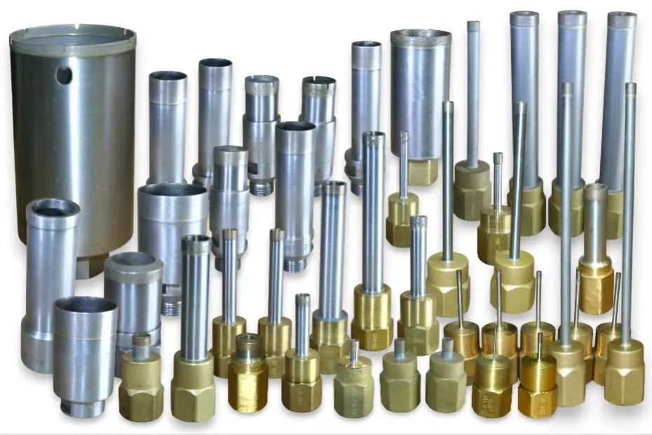
Available diameters |
Typically 0.5 inch to 12 inch standard catalog |
0.5 inch to 48 inch |
Typically 0.5 inch to 6 inch |
|
Recovery from glazing |
Possible with dressing if bond not destroyed |
Recoverable in most cases; bond maintains consistent cutting force over tool life |
Not recoverable; single-layer diamond lost permanently |
|
Best application fit |
General stone, construction, low-precision work |
Optical glass, ceramics, sapphire, semiconductor, stone, precision production runs |
Very hard materials, thin walls, single-use or short-run applications |
Machine and Spindle
- Spindle runout verified with dial indicator (target: under 0.001 inch)
- SFM: 200 to 500; composites tolerate higher speeds but require delamination monitoring
- Coolant: Air blast or fine mist. Confirm compatibility with specific matrix system before using water-based coolant.
Coolant System
- Flow rate measured at nozzle or swivel exit, not at pump
- Pressure confirmed per drill OD reference table
- Coolant type confirmed for material (synthetic fluid, plain water, air blast, or mist)
- Center-feed system or water swivel adapter available for holes deeper than 2× drill diameter — see available diamond tool accessories
- Coolant flow verified as uninterruptible through full drilling cycle
Tool Specification
- Bond hardness matched to material abrasiveness per reference table
- Rim geometry confirmed (segmented for hard/abrasive; continuous crown for optical and semiconductor)
- Wall thickness selected for balance of heat control and required rigidity
- Dressing stick (AlO2) available on machine — available as part of UKAM's diamond consumables
Process Parameters
- SFM calculated from drill OD; RPM set from SFM, not from a generic table
- Feed pressure set to minimum penetration threshold
- Peck drilling cycle planned for holes deeper than 25.4 mm
- Backing material available for breakthrough management
- Drilling log format prepared: SFM, coolant flow, holes per dress, cycle time, scrap count

Frequently Asked Questions
- No. Dry contact of even 3 to 5 seconds generates micro-fractures in optical glass and fused silica.
- These fractures are invisible on the surface and cause part failure during polishing, coating, or assembly.
- There is no safe dry-contact window. Use flood coolant or a water dam setup without exception.
- Stop immediately. Restore full coolant flow before retracting the drill.
- Inspect the cutting face. A shiny, smooth face with no visible diamond means the tool is glazed.
- Dress on an AlO2 dressing stick, reduce SFM, and verify coolant flow before resuming.
- Sintered drills are often recoverable if the smoking was brief. Electroplated tools are not — the single diamond layer cannot be regenerated by dressing.
- Bond hardness mismatch: a bond too hard for the material will not self-dress, so worn diamonds stay embedded regardless of coolant volume.
- Coolant not reaching the cutting face: flood coolant cannot penetrate holes deeper than 2x drill diameter. Switch to center-feed delivery.
- SFM too high: excessive surface speed softens the bond matrix faster than the workpiece can drive self-dressing.
- Yes, directly. Thinner walls reduce contact area per revolution, which reduces friction heat per cycle.
- Thinner walls also improve chip clearance through the annular gap, the primary path for swarf and heat removal.
- The tradeoff is rigidity. For optical and semiconductor drilling, 0.5 to 1.0 mm wall is typically correct. For deep holes in granite or hard stone, heavier wall specifications are required for stability.
- A cycle where the drill is retracted at regular depth increments to flush swarf and allow coolant to reach the cutting face.
- Required for any hole deeper than 25.4 mm (1 inch) in hard or brittle materials.
- Retract every 6 to 12 mm of depth. CNC equipment can automate this. Manual setups require operator discipline.
- Peck drilling supplements coolant delivery. It does not replace it.
- Correct frequency: cycle time and swarf color remain stable from first hole after dressing to last hole before next dress.
- Interval too long: cycle time increases more than 15% before the scheduled dress.
- Interval too short: performance drops off sharply after a few holes, indicating a bond hardness mismatch rather than a dressing schedule problem.
- Hard dense materials: dress every 10 to 20 holes. Softer materials: dress on condition, tracked by log.
- Primary cause: coolant reservoir warming. Coolant above 35 to 40 degrees Celsius loses measurable cooling efficiency.
- Solutions: larger reservoir with greater thermal mass, recirculating chiller, or periodic coolant replacement during the shift.
- Secondary cause: swarf contamination in the coolant reducing flow efficiency at the nozzle. Filter and circulate coolant regularly.
Not sure which specification fits your application?
UKAM engineering reviews your material, machine, hole diameter, and production volume before recommending a drill — no catalog guesswork. UKAM has manufactured precision diamond tools for industry, research institutions, and specialized applications since 1990. Every tool is backed by expert technical support.
→ Request a Free Application Consultation
Trusted by Tens of Thousands of Manufacturers, Laboratories,
Research Institutions Worldwide Since 1990
American Based Manufacturer
Established in 1990
Custom manufacturing
RELATED ARTICLES