Selecting the Right Wafer Dicing Saw Practical Guide
-
Posted by
contactor6
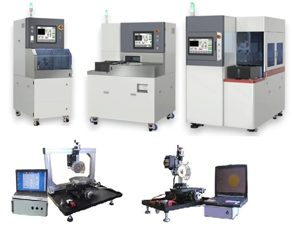
Table of Contents
ToggleSelecting the proper wafer dicing saw is a important decision for manufacturers, researchers, and engineers working with large variety of materials. Whether processing silicon wafers in microelectronics, ceramics in materials science, or glass substrates in optics, the efficiency and reliability of the dicing system directly influence yield, productivity, and overall process economics.
Modern wafer dicing has largely replaced older methods such as scribe-and-break or manual separation. Diamond dicing saws allow precise cutting of hard and brittle materials with minimal kerf loss and controlled edge quality. This capability has made them the standard choice across industries that require precision at the micron level. However, choosing the right equipment is not straightforward. Each application presents its own unique challenges, and performance depends on the interaction of multiple variables.
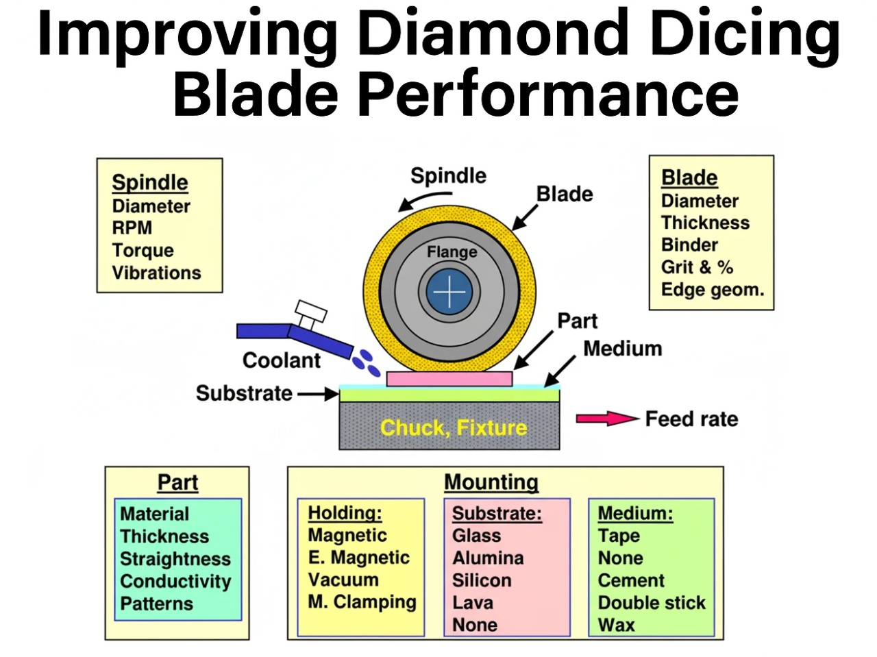
A successful dicing system cannot be defined by the machine or blade alone. Instead, it must be viewed as a complete system where equipment, blades, operating parameters, and workpiece characteristics interact. Substrate material type, thickness, geometry, desired cut quality, spindle speed, feed rate, mounting method, coolant delivery, and blade specifications all play interconnected roles. If just one variable is selected incorrectly, even the best blades and machines will fail to deliver the required results.
This article provides a information on dicing saw types, their application and structured approach for selecting wafer dicing equipment. It begins with the fundamental requirements of rigidity, power, and cooling, and continues through machine design, blade selection, and operating parameters. The goal is to equip you with the knowledge needed to make informed decisions, reduce costly trial-and-error, and achieve consistent, high-quality results in your dicing operations.
Dicing Saw Types and their Application
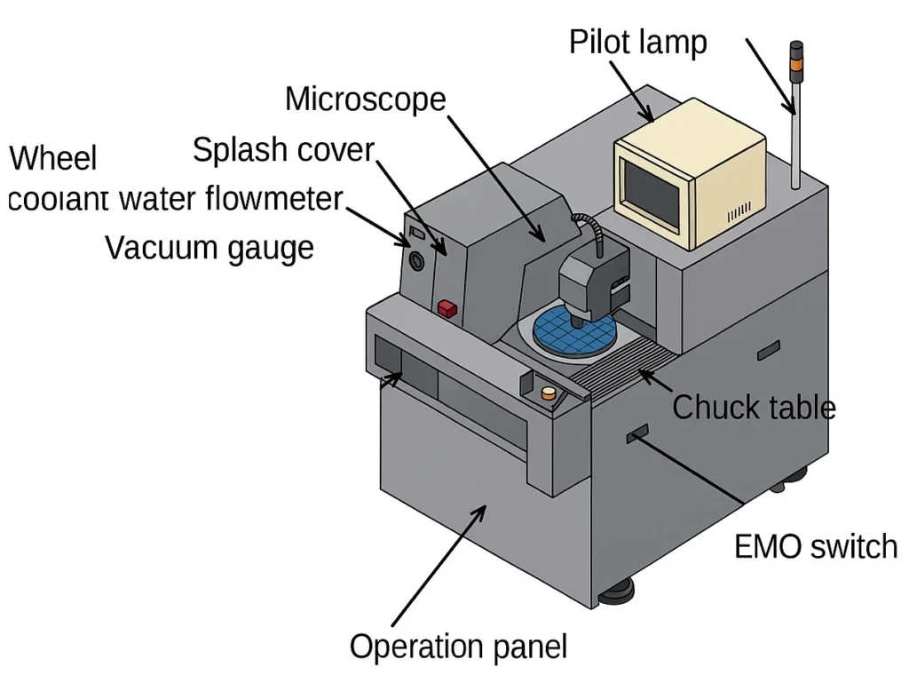
Dicing saws come in different classes, each designed for a specific balance of flexibility, throughput, and automation. Tabletop dicing saws are compact, affordable systems built for R&D labs, universities, and prototyping, where versatility and low cost matter more than speed. Semi-automatic saws provide a step up, supporting larger wafer diameters, wider substrate thickness ranges, and higher spindle speeds, making them suitable for low- to medium-volume production and pilot lines that need precision and adaptability without the expense of full automation. At the other end are dual-spindle fully automatic saws, engineered for semiconductor fabs and packaging facilities where 24/7 high-throughput operation, advanced vision systems, and process automation are critical. Understanding these categories ensures that the saw you select matches both your technical requirements and your production volume.
Tabletop Dicing Saws for R&D and Universities
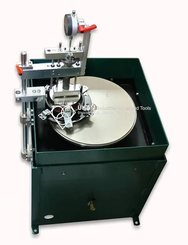
Small tabletop dicing saws are designed for environments where flexibility, compact size, and affordability are more important than throughput. These machines are common in research laboratories, universities, and prototype facilities, where users often cut a wide range of materials from silicon wafers and MEMS devices to ceramics, glasses, composites, and specialty crystals in small batch sizes.
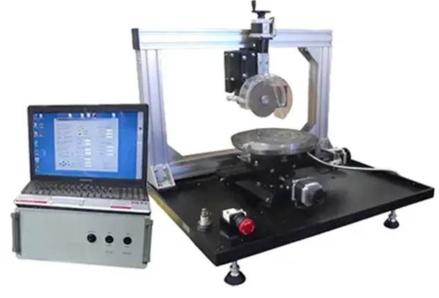
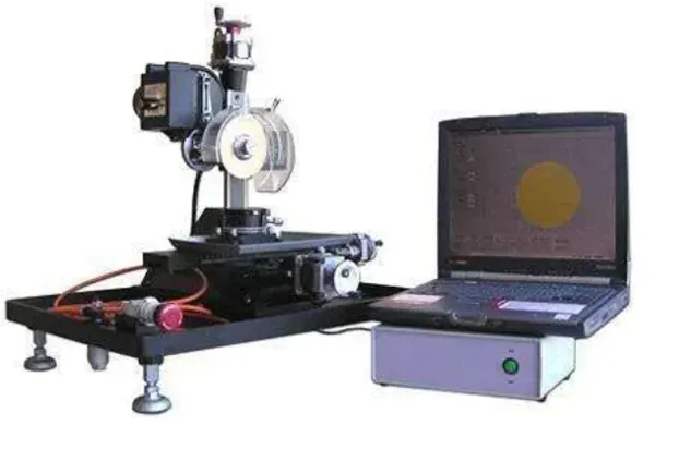
Because they are compact, these saws require minimal facility modifications. Many can operate in a standard lab setting without the need for heavy vibration isolation, large air supplies, or extensive cooling infrastructure. They typically use single-spindle designs with 3” to 6” (75mm to 150mm) dicing & slicing blades, supporting thin kerfs ideal for precision cuts in brittle or delicate substrates. Thinnest Kerf thickness they can accommodate is .004” (100 microns) and cut materials as thick as 1”. These machines utilize 4” (100mm) to 8” (200mm) vacuum chucks, and variety of mechanical holding fixtures and rotary table. They operate at 100 to 3,500 RPM’s. These machines can be used manually using rotary handles or controlled through a regular pc computer using stepper motors.
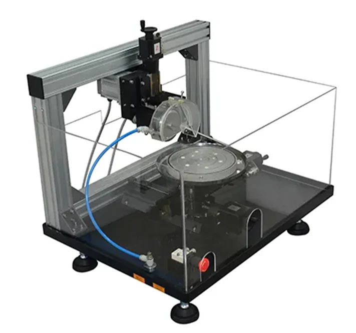
The focus of tabletop saws is versatility rather than volume. They allow easy blade changes, manual or semi-automatic alignment, and often have open-architecture control software so researchers can quickly adjust spindle speed, feed rate, and coolant flow for different materials. Some also provide basic vision systems for fiducial recognition and alignment, though these are simpler than the high-speed optics found in production saws.

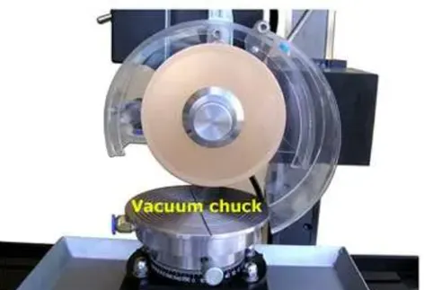
While their throughput is limited, tabletop saws excel in occasional dicing, prototyping, and material testing. They provide a cost-effective way to explore new processes or prepare samples without committing to the high investment and operating costs of a fully automatic system. For universities, they are also valuable teaching tools, allowing students to gain hands-on experience with wafer preparation, process control, and materials science.
Semi-Automatic Dicing Saws
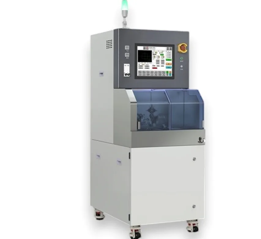
Semi-automatic dicing saws are designed for R&D, universities, and low-volume production where flexibility and cost efficiency are more important than throughput. Operators manually load and unload wafers or substrates, and while vision systems assist alignment, they typically require some operator input. Recipes can be stored for repeat jobs, but automation features such as cassette loading, wafer mapping, or auto-cleaning are limited compared to fully automatic machines.
Most semi-automatic systems can handle up to 6-inch (150 mm) wafers, though advanced configurations can process 8-inch or even 12-inch (300 mm) wafers. They support a wide range of substrate thicknesses, from thin wafers below 100 µm (mounted on tape) to materials 8–10 mm thick, including ceramics, glass, and sapphire, provided the correct blade and spindle are used.
The spindle speed range typically falls between 3,000 and 60,000 RPM, depending on the spindle option. Higher speeds are used for thin silicon wafers and delicate substrates, while lower speeds are necessary for hard, brittle materials such as quartz, sapphire, or alumina to minimize chipping and cracking. Standard spindle power is about 1.8 kW, with 2.2 kW high-torque spindles available for applications that require deeper cuts or harder materials.
Semi-automatic saws usually use 2-inch dicing blades, available in hubbed or hubless configurations, with kerf widths ranging from 15 µm to 300 µm depending on the material. Vision systems typically include a top camera with coaxial or ring lighting for fiducial recognition, while advanced features such as die shift compensation or backside alignment are reserved for production-class equipment.
The advantages of semi-automatic dicing saws include lower capital cost, compact footprint, and adaptability to a wide variety of materials. They are well suited for environments where different substrates may be cut daily — for example, silicon wafers in the morning, ceramics in the afternoon, and optical glass later in the day. Setup changes are straightforward because the operator remains in control of most steps.
However, these systems are not intended for continuous or high-volume production. Labor costs are higher due to manual handling, throughput is limited, and yield stability may vary depending on operator skill. For this reason, semi-automatic saws are best viewed as flexible, precision tools for research and specialty applications, rather than production workhorses.
Dual-Spindle Fully Automatic Dicing Saws
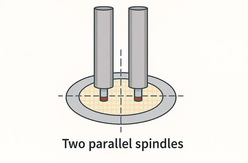
At the high end of dicing technology are dual-spindle fully automatic dicing saws, built for mass production and high-throughput environments such as semiconductor fabs, advanced packaging facilities, and LED manufacturing lines. These systems feature two independent spindles operating in parallel, allowing two cuts to be performed simultaneously. This design nearly doubles throughput compared to single-spindle machines, making it especially valuable for processing 300 mm wafers, QFN/BGA panels, or high-volume LED substrates where efficiency and yield are critical.
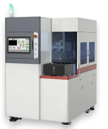
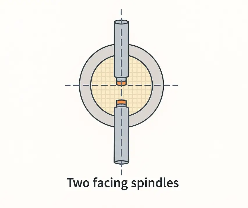
Wafer and Substrate Handling- Dual-spindle saws can accommodate up to 12-inch (300 mm) wafers as well as large panels and multi-substrate frames used in panel-level packaging. They are optimized for handling ultra-thin wafers (below 100 µm) mounted on tape, as well as standard-thickness wafers and panels up to 2–3 mm thick. Some configurations also support step-cutting or partial depth cutting for multi-layer substrates such as laminated ceramics and advanced packaging materials.
Spindle Speed and Power – These machines are typically equipped with high-speed spindles offering ranges from 3,000 to 60,000 RPM, with precise control to match different material requirements. Dual-spindle systems may use two identical spindles for maximum throughput, or be configured with different spindle types (e.g., one high-RPM, one high-torque) to handle different blade types and cut depths in the same run. Spindle power is generally higher than semi-automatic systems, often in the 2.2–3.0 kW range, providing the torque necessary for long continuous runs and harder materials.
Automation and Vision Systems – Dual-spindle dicing saws are equipped with advanced automation features to minimize operator intervention. Standard functions include cassette loading/unloading, wafer mapping, recipe-driven alignment, kerf measurement, and spindle load monitoring. Some models also include auto-dressing of blades, ensuring consistent performance without manual maintenance.
The vision systems are highly sophisticated, incorporating automatic fiducial recognition, die shift compensation, street mapping, and real-time path correction. High-resolution top and bottom cameras, combined with laser or non-contact height measurement, guarantee precise alignment and depth control even across warped or bowed wafers. These features allow continuous processing of thousands of wafers with minimal human oversight, ensuring both throughput and repeatability.
Operational Requirements – The trade-offs of dual-spindle systems are clear: they come with higher capital cost, larger footprint, and greater infrastructure requirements. They require clean dry air, stable high-volume coolant supply, reliable power, and vibration-free installation. Maintenance demands are also higher, with scheduled preventive service and trained staff required to sustain 24/7 operation. However, for facilities processing tens of thousands of wafers or panels per month, the investment is justified by the dramatic reduction in cost per cut and the ability to maintain tight process control and yield stability.

Application Fit
Dual-spindle fully automatic saws are justified only when volume is consistently high enough to leverage their throughput advantage. They are the machine of choice when cutting large volumes of silicon wafers, advanced packaging substrates, or high-density LED panels, where yield and productivity directly determine profitability. For R&D, specialty production, or low-volume operations, the cost, complexity, and infrastructure demands cannot be justified.
Selecting the Right Dicing Saw: The 12 Requirements You Must Consider
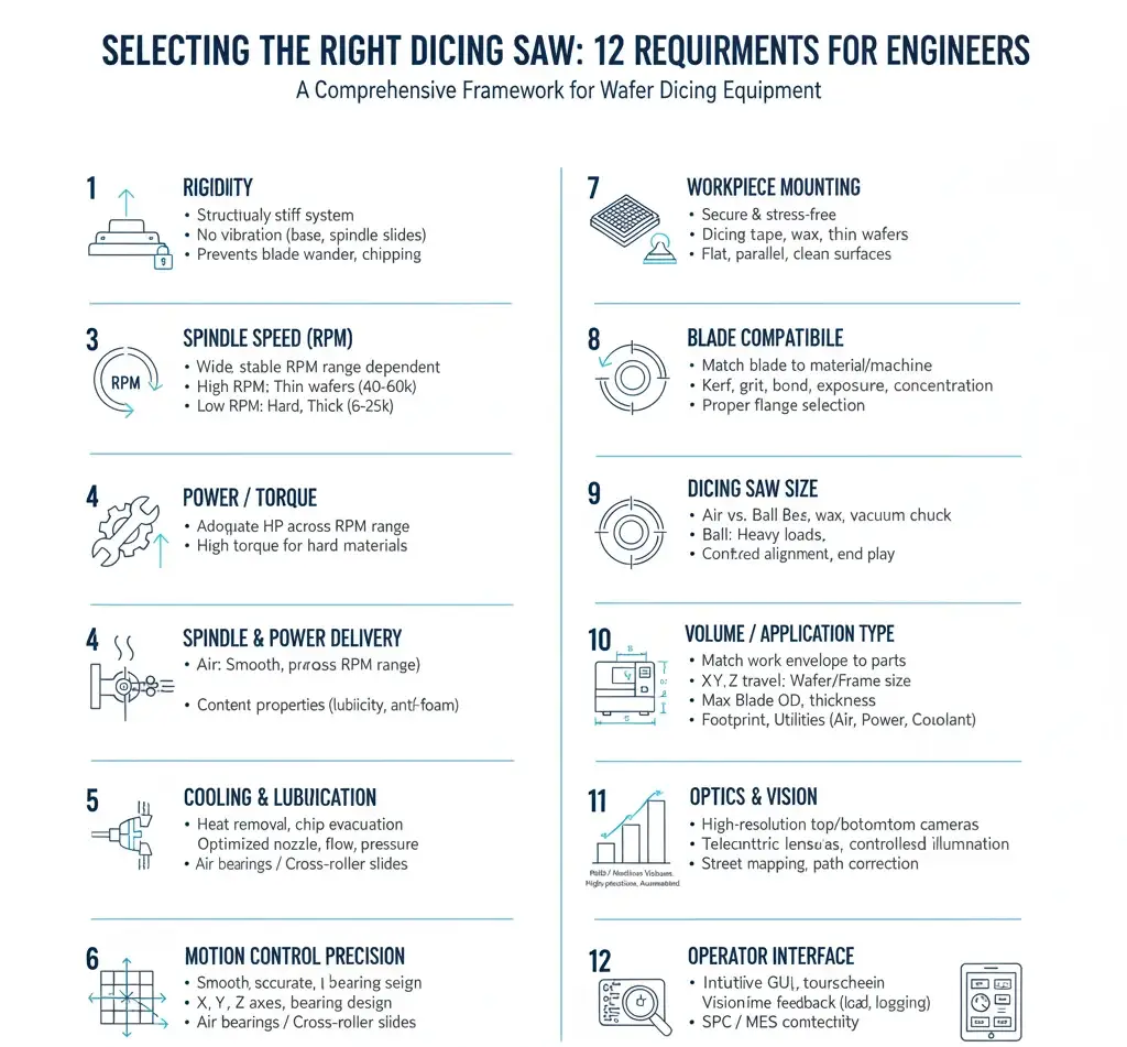
A high-performance wafer dicing process depends on more than just a dicing blade with properly exposed diamond crystals and a stable machine. For consistent results, the system must satisfy several fundamental requirements. Traditionally, these were summarized as rigidity, power, and cooling, but modern applications demand a broader view. The following twelve requirements provide a more complete framework for selecting and operating wafer dicing equipment.
1. Rigidity
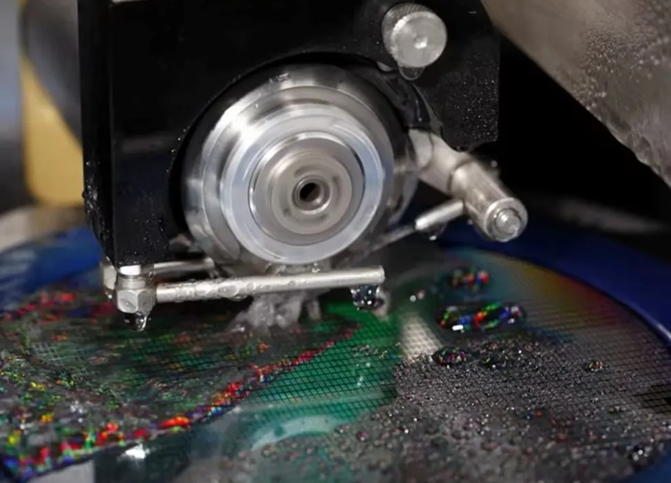
The entire system must be structurally stiff and free from excessive vibration. This applies to the machine base, spindle, slides, flanges, and workpiece mounting method. A lack of rigidity causes blade wander, excessive chipping, and dimensional inaccuracies. For precision cutting, the flange size should be provide minimum blade exposure, and workpiece mounting must ensure flatness and stability throughout the operation.
2. Spindle speed (RPM)
Spindle speed / rpm’s is one of the most important factors in selecting a dicing saw, since it controls which materials and thicknesses can be cut, as well as cutting aggressiveness, surface finish, heat, and process stability. Silicon wafers are usually processed at 20,000–40,000 RPM, glass and quartz at 6,000–20,000 RPM, and sapphire, silicon carbide, and advanced ceramics at 8,000–25,000 RPM, while ultra-thin wafers below 100 µm may require 40,000–60,000 RPM. Higher speeds support fine kerfs in thin, delicate substrates, while lower speeds are better for hard, thick, brittle materials. The best dicing saw is therefore one with a wide, stable RPM range and sufficient torque across all speeds, giving the flexibility to handle different materials, geometries, and thicknesses while maximizing yield, blade life, and throughput.
3. Power
The machine must supply adequate horsepower and torque across the full spindle speed range. Cutting harder materials such as sapphire, silicon carbide, or advanced ceramics often requires lower spindle speeds with high torque output. If the spindle loses power at reduced speeds, the operator may be forced to cut too aggressively, which reduces blade life and surface quality. Selecting a machine with the correct torque curve and variable speed capability is critical.
4. Spindle and Power Delivery
The spindle is the core of any dicing machine, and its performance depends on both horsepower rating and torque at different RPM ranges. Many spindles lose torque at low speeds, making it difficult to cut hard, brittle materials that require slower blade rotation. The choice between air-bearing and ball-bearing spindles is also critical: air bearings provide smoother, high-precision rotation for thin wafers, while ball bearings handle heavier loads and multi-blade cutting but with more vibration. Finally, spindle alignment and end play must be tightly controlled, since even small deviations cause blade deflection, reduced accuracy, and shorter blade life.
5. Cooling and Lubrication
A well-designed coolant system ensures heat removal, chip evacuation, and surface protection. The nozzle design, flow rate, and pressure must be optimized for each blade and material. Advanced coolants also provide lubricity to reduce friction, anti-foaming properties for stable delivery, and in some cases ESD protection for sensitive substrates. Poor coolant performance leads to thermal damage, blade glazing, and micro-cracks.
6. Precision of Motion Control
- The machine’s X, Y, and Z axes must deliver smooth, accurate, and repeatable positioning. Precision depends on bearing design, feed system quality, and control software. Excessive runout or misalignment between the spindle and blade path will cause miscuts, even if rigidity and power are sufficient. In high-tolerance applications, air bearing spindles or cross-roller slides are often used to improve accuracy.
7. Workpiece Mounting Stability
The substrate must remain secure and stress-free throughout the process. Common mounting methods include dicing tape, wax mounting, or vacuum chucks. Mounting surfaces must be flat, parallel, and clean, as even small distortions can transfer stress to the blade, leading to chipping or cracking. For fragile wafers, the choice of mounting adhesive or tape type can determine yield.
8. Blade Compatibility
The blade design must match the material and machine parameters. Important factors include kerf thickness, diamond grit size, bond type, exposure height, and concentration. A mismatch—such as using a blade with too thin a kerf on an underpowered spindle—can cause premature blade failure. Proper flange selection and installation are also essential to keep the blade running true.
9. Dicing saw size
Select the saw size by matching the work envelope to your parts. Confirm X, Y, and Z travel against your largest substrates and street maps. Verify the maximum wafer or panel size, tape frame size, and chuck format. Common needs are 2 to 12 inch wafers and 6 to 12 inch frames. Check the maximum blade outside diameter the spindle and guards can accept. Many applications use 2 to 6 inch diamond dicing blades. Confirm the compatible blade thickness range and maximum safe exposure height. Validate flange diameter and stiffness. Match machine footprint and weight to your facility. Benchtop saws save space but require careful vibration isolation. Floor units provide higher mass and stability. Confirm utilities. You need enough clean dry air for air bearings if equipped, stable power, and adequate coolant supply and return.
10. Volume of Use / Application Type
The volume of use and type of application are key factors in selecting the right dicing saw. A machine suitable for R&D and occasional dicing must offer flexibility and adaptability, while a saw intended for pilot or medium-volume production requires greater rigidity, power, and semi-automation. For full-scale mass production, only a high-precision, automated saw designed for continuous operation can deliver the required throughput, stability, and yield. Matching the saw class to your actual workload ensures efficiency, reliability, and cost-effectiveness.
11. Dicing saw optics and vision
Optics and vision determine alignment speed and yield. Require a high resolution top camera with repeatable calibration to the spindle center. Specify telecentric or low distortion lenses when your streets are narrow. Use controlled illumination. Combine coaxial, ring, and side lighting to reveal scribe lines, fiducials, or metallization. If you dice thinned wafers on tape, consider a bottom camera for backside alignment through transparent carriers. Demand repeatable autofocus or laser height sensing for consistent edge sharpness. Insist on automatic fiducial recognition, scribe line tracking, and kerf measurement. The software should support street mapping, compensation for die shift, and real time path correction. Good vision reduces setup time, prevents miscuts, and raises first pass yield.
12. Dicing Saw Operator Interface
The operator interface of a dicing saw is just as important as its hardware, since it controls how easily the machine can be set up, monitored, and maintained. A well-designed graphical interface with touchscreen controls allows operators to quickly adjust spindle speed, feed rate, cut depth, and coolant flow, while also providing real-time feedback on spindle load, coolant pressure, and temperature. Integrated vision alignment tools speed up fiducial recognition and street mapping, reducing setup time and improving yield. An intuitive interface also shortens operator training, minimizes errors, and in production environments should support data logging, SPC, and MES connectivity. In practice, the right dicing saw combines powerful hardware with a user-friendly control system, ensuring consistent performance, efficiency, and reliability.
1. Rigidity
Rigidity is the foundation of any dicing system. The entire machine must be structurally stiff and free from vibration, because even the smallest deflection is magnified at the cutting edge, where tolerances are measured in microns. Rigidity applies not only to the machine base, but also to the spindle, slide assemblies, flanges, and workpiece mounting method. If any of these components flex or vibrate, the result will be blade wander, excessive chipping, uneven kerf widths, and dimensional inaccuracies.
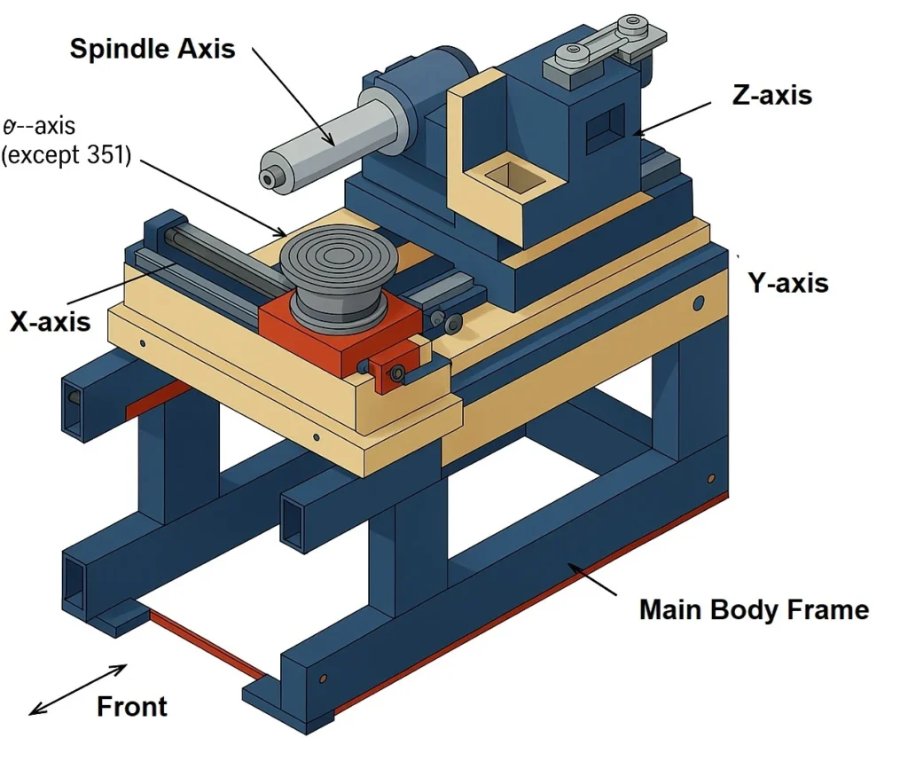
The machine base should provide high mass and stability to damp vibrations, especially in production environments. Floor-mounted saws generally offer more rigidity than compact benchtop units, though the latter can still achieve precision if they are installed on vibration-isolated tables. The spindle housing and bearings must be designed to minimize runout and resist deflection under cutting loads. Poor spindle rigidity leads directly to reduced blade life and inconsistent cuts.
Slides and feed systems are another critical factor. Cross-roller bearings, linear guides, or air-bearing stages must hold tight tolerances during motion. Even slight play or backlash in the X, Y, or Z axis will cause the blade to deviate, resulting in miscuts or uneven die sizes. High-end systems use air-bearing spindles combined with linear motor drives to achieve the smoothest motion and highest precision.
Flanges and blade support are equally important. A practical guideline is that flange diameter should be at least one-third of the blade diameter to provide adequate stiffness. Undersized or uneven flanges allow the blade to flex or wobble, increasing kerf variability and chipping. Flanges should be flat, parallel, and free of contamination to ensure full contact with the blade.
Finally, the workpiece mounting method must secure the substrate in a flat and stable position. If the wafer or panel bows or shifts during cutting, the blade is forced off-path, causing micro-cracks, yield loss, and accelerated wear. For ultra-thin wafers, rigidity at the chuck and tape frame is especially critical, since even slight warping can result in misalignment.
When selecting a dicing saw, always evaluate the machine’s rigidity as a complete system. Ask about base construction, spindle stiffness, slide accuracy, flange design, and chuck flatness. A rigid system ensures that the blade cuts cleanly and predictably, extending tool life and maximizing yield. Without it, even the best blade and coolant system will not deliver consistent results.
2. Spindle Speed (RPM)
When selecting the right dicing saw for your application, one of the most important operating parameters is the spindle speed (RPM). The spindle determines the peripheral speed of the dicing blade, which directly affects cutting aggressiveness, surface finish, heat generation, and overall process stability.

Different materials respond best to different spindle speed ranges. Silicon wafers, which make up the majority of semiconductor processing, are typically diced in the range of 20,000 to 40,000 RPM. This range provides a balance between throughput and cut quality. Glass and fused quartz, which are prone to edge chipping, perform better at 6,000 to 20,000 RPM, where slower cutting reduces stress and improves surface integrity. Sapphire and silicon carbide, both extremely hard and brittle, are usually cut at 8,000 to 25,000 RPM, since lower speeds help prevent micro-cracks. Advanced ceramics such as alumina (Al₂O₃), zirconia (ZrO₂), and silicon nitride (Si₃N₄) also fall into the 6,000 to 20,000 RPM range, depending on thickness and required cut quality. For ultra-thin wafers (below 100 µm) and delicate substrates used in MEMS and advanced packaging, higher spindle speeds of 40,000 to 60,000 RPM may be necessary to achieve very fine kerfs and smooth edge quality.
It is important to recognize the trade-off between cutting aggressiveness and heat generation. Higher spindle speeds make the blade cut more aggressively and remove material faster, but they also generate more heat at the cutting zone. Excessive heat can cause thermal damage, bond softening, or substrate distortion. Lower spindle speeds reduce thermal load and often improve surface finish, but they demand higher spindle torque and longer cutting cycles.
For this reason, the best dicing saw is not the one with the highest maximum RPM, but the one that offers a wide, stable, and controllable RPM range with adequate torque at both high and low speeds. A properly matched saw allows you to fine-tune spindle speed for each material, ensuring a balance of throughput, blade life, and cut quality.
3. Spindle and Power Delivery
The spindle is the heart of a wafer dicing machine, responsible for driving the diamond blade at the required speeds and forces. The performance of the spindle determines not only the cutting capability of the system but also the quality, accuracy, and consistency of the finished parts. When evaluating dicing equipment, careful attention must be given to horsepower rating, torque curve, spindle design, and alignment precision.
Horsepower and Torque
The horsepower rating of the spindle defines the maximum power available for cutting. However, what matters equally is the torque available across different spindle speeds. Many machines are rated for maximum power at the top end of their RPM range (often around 30,000 RPM). At lower speeds, torque can drop sharply, making it difficult to cut hard and brittle materials such as sapphire, silicon carbide, or advanced ceramics, which require lower blade speeds for controlled cutting.
If torque is insufficient at low RPM, the blade may stall or force the operator to cut at higher-than-recommended speeds. This often results in excessive heat generation, edge chipping, and reduced blade life. A proper machine should therefore be selected based on its torque curve, not just its advertised horsepower.
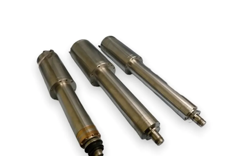
Air-Bearing vs. Ball-Bearing Spindles
Spindles are generally built with either air bearings or ball bearings, each with distinct advantages:
Air-Bearing Spindles
- Advantages: Provide exceptionally smooth, frictionless rotation, ideal for high-speed and ultra-precision applications such as cutting silicon wafers or delicate optics. They generate minimal vibration and runout.
- Limitations: Require very clean air supply and strict maintenance. More expensive and sensitive to contamination. Life span depends heavily on operator care.
Ball-Bearing Spindles
- Advantages: Offer higher load capacity and are better suited for heavy-duty cutting applications involving thicker ceramics, composites, or multi-blade gang cutting. More robust and less sensitive to contamination than air bearings.
- Limitations: Produce more vibration and runout compared to air bearings. Not as smooth for extremely fine precision cuts. Bearings eventually wear out and require replacement.
The choice between air and ball-bearing spindles depends on material type, cut thickness, and precision requirements. For microelectronics and ultra-thin substrates, air-bearing spindles are preferred. For industrial ceramics or high-throughput cuts, ball-bearing spindles provide durability and strength.
Spindle Alignment and End Play
Even the most powerful spindle will fail to perform if it is not properly aligned. End play (axial looseness) and radial runout (side wobble) introduce inaccuracies that are magnified at the micron level. These imperfections lead to blade deflection, inconsistent kerf width, and accelerated blade wear.
To maintain accuracy, the spindle must remain perpendicular to the feed axis and free of measurable end play. Proper blade mounting with clean, flat flanges is equally important, since even microscopic dirt or flange distortion can cause the blade to run off-center. Consistent inspection and maintenance of spindle alignment are essential for extending blade life and ensuring cut quality.
Spindle Size
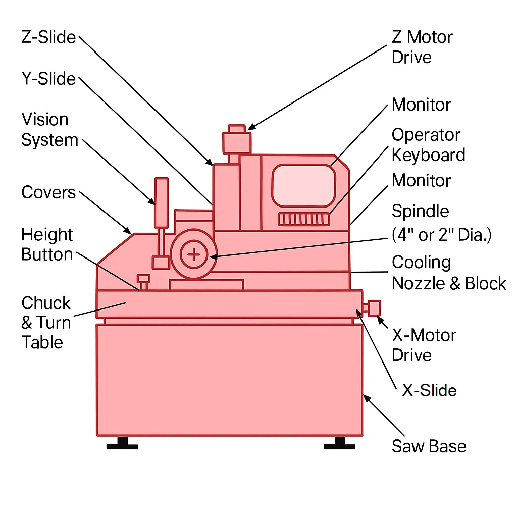
When choosing a dicing saw for your application, one of the most important but often overlooked considerations is the spindle size. The spindle not only holds and drives the blade but also defines the range of blade diameters, thicknesses, and materials the machine can effectively cut. Selecting the wrong spindle size can limit your flexibility, reduce blade life, and compromise cut quality.
Smaller spindles (typically 2″) are designed for thin, fine-kerf dicing blades. These are commonly used for semiconductor wafers, MEMS devices, LEDs, and delicate optical substrates where blade thicknesses are in the range of 15–100 µm. The smaller spindle reduces inertia, supports higher RPM ranges (20,000–60,000 RPM), and allows for extremely precise cuts with minimal kerf loss. However, they are less suited for thick or very hard materials, since the spindle cannot support large, heavy blades or the higher cutting forces required.
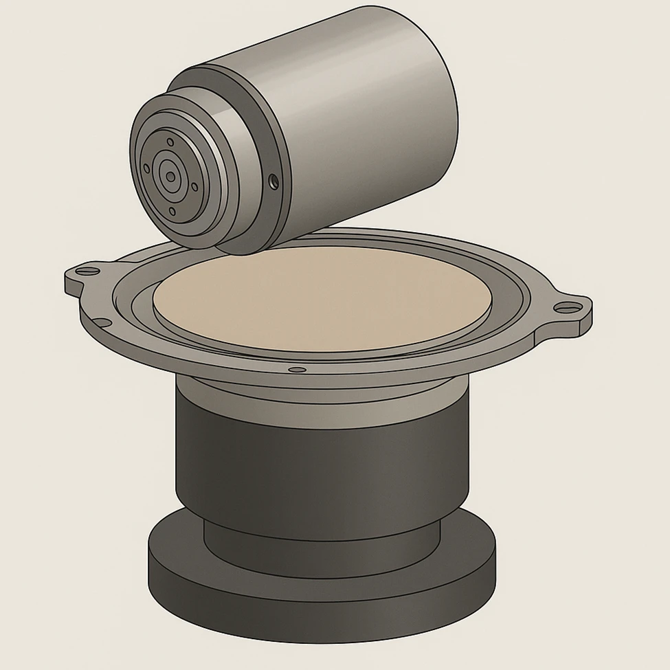
Larger spindles (4″ and above) are designed for thicker and more rigid dicing blades, often in the range of 200–500 µm kerf thickness. These spindles provide the stiffness and load-bearing capacity needed for hard materials such as sapphire, alumina, zirconia, and ceramics, or for thicker substrates that require deeper cuts. They typically operate at lower maximum RPMs than small spindles, but deliver the torque and rigidity necessary for stable cutting of hard, dense materials.
Matching spindle size to your application ensures the saw can use the correct blade type. A 2″ spindle saw cannot reliably run a large, heavy metal-bond blade designed for sapphire, and a 4″ spindle saw cannot provide the rotational speeds required for ultra-thin kerf silicon wafer dicing. In short, the spindle size determines the material range, blade compatibility, achievable RPM, and cutting stability of the saw.
When selecting a dicing saw, always consider:
- What materials will you cut most often?
- What thicknesses must be processed?
- What kerf width is required for yield and die size?
- Do you need versatility (R&D, mixed materials) or specialization (high-volume production)?
The right spindle size ensures that your saw is optimized for your workload, balancing speed, precision, and rigidity. Ignoring spindle size can result in premature blade failure, excessive chipping, or a machine that cannot adapt to your production requirements.
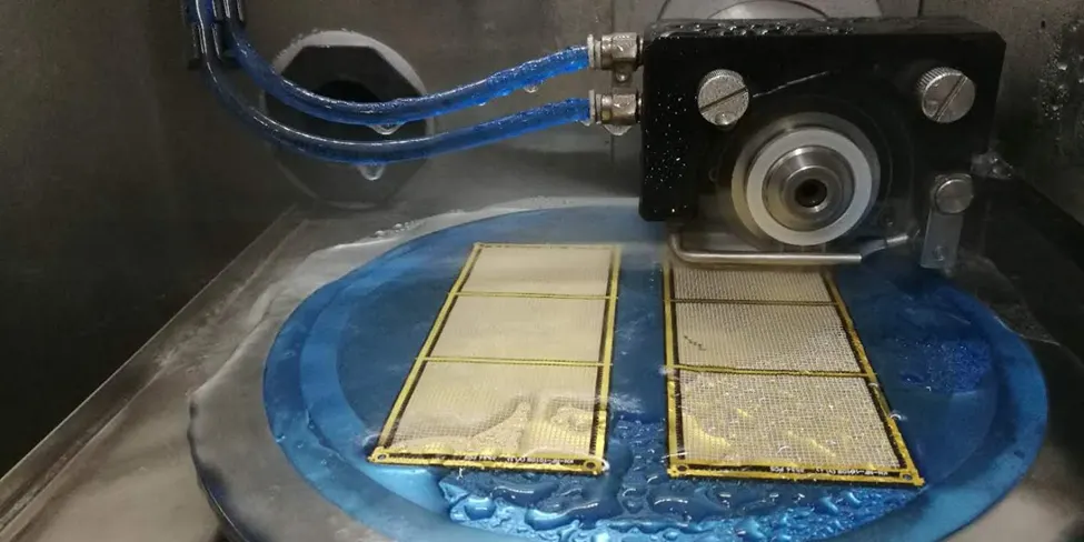
4. Cooling and Lubrication
When selecting a dicing saw, the cooling and lubrication system must be evaluated as carefully as the spindle or optics, since it directly determines blade life, cut quality, and yield. A well-designed coolant system does more than keep the blade wet, it provides heat removal, chip evacuation, and surface protection at the cutting zone. Without effective cooling, even the best blade and most rigid machine will underperform.
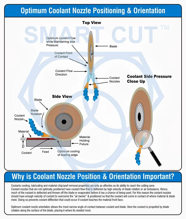
The nozzle design, flow rate, and pressure must be matched to both the blade type and material. A nozzle that fails to deliver coolant directly into the kerf leads to localized overheating, which causes thermal damage, substrate cracking, or bond softening. Conversely, excessive flow can create turbulence that interferes with chip evacuation. The right dicing saw should allow precise positioning of nozzles and stable pressure control, ensuring consistent delivery to the blade–material interface.
Advanced dicing coolants are equally important. Beyond basic water-based fluids, specialized formulations provide extra lubricity to reduce cutting friction, low-foaming properties for stable delivery, and in some cases anti-static protection (ESD) for sensitive semiconductor wafers. Matching the coolant type to your application is critical: for example, optical glass and quartz benefit from high-lubricity fluids to prevent edge chipping, while semiconductor wafers often require ESD-safe fluids to protect delicate circuits.
Poor coolant performance shows up in multiple ways: blade glazing, premature wear, micro-cracks, and excessive chipping. These failures often lead users to mistakenly blame the blade or machine, when in reality the coolant system was the weak link. When evaluating a dicing saw, confirm not only its coolant delivery system design but also its filtration capability. For high-precision applications, filtration should be at least 5 microns or finer to prevent particles from re-entering the cut and scratching the substrate.

5. Precision of Motion Control
When choosing a dicing saw, one of the most critical factors is the precision of motion control. The X, Y, and Z axes must provide smooth, accurate, and repeatable positioning, since even slight deviations can compromise cut quality and yield. A machine may have sufficient rigidity and spindle power, but without precise motion, the result will be miscuts, inconsistent kerf widths, and damaged parts.
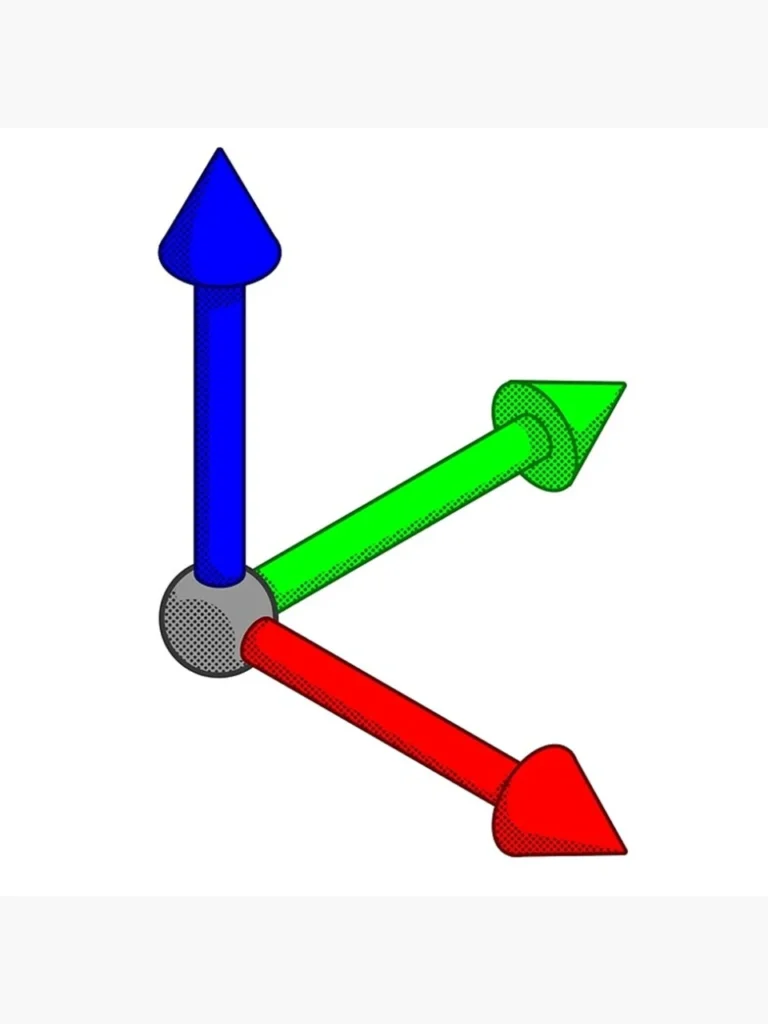
The accuracy of motion control depends heavily on bearing design, feed system quality, and control software integration. Cross-roller slides, linear guides, or air-bearing stages are commonly used in high-precision dicing saws to minimize friction and vibration. In particular, air-bearing spindles and linear slides excel in applications requiring sub-micron accuracy, such as thin semiconductor wafers or optical components. For thicker ceramics and composites, precision ball-screw or linear motor drives may be more practical, offering durability alongside accuracy.
Equally important is the alignment of the spindle to the blade path. Excessive runout or misalignment between the spindle axis and the cutting path leads to blade wobble, uneven kerfs, and accelerated blade wear. A properly designed dicing saw will maintain perpendicularity and parallelism across all axes, ensuring the blade cuts cleanly and consistently.
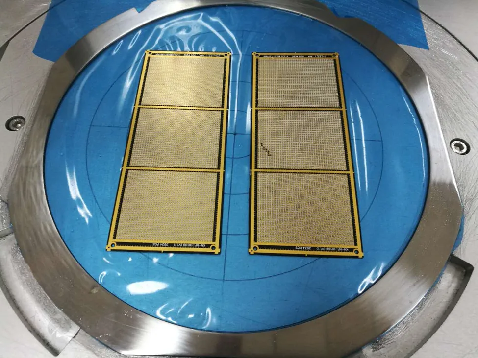
The control software and motion controller also play a key role. Advanced systems feature closed-loop feedback, which constantly monitors and adjusts motion to compensate for thermal drift, load changes, or vibration. This ensures that cuts remain accurate even during long production runs. For R&D and prototyping, open-architecture motion software allows operators to fine-tune movements and experiment with different cut paths, while in production environments, recipe-driven software ensures repeatability across high-volume batches.
When selecting a dicing saw, always evaluate the motion system specifications—including positional accuracy, repeatability, backlash, and spindle runout tolerance. For advanced semiconductor work, tolerances must often be within a few microns, while for cutting thicker ceramics or substrates, slightly looser tolerances may be acceptable. The correct system depends on your material, thickness, and cut quality requirements.
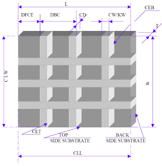
6. Workpiece Mounting Stability
The stability of the workpiece mounting system is just as important as spindle power or machine rigidity when selecting a dicing saw. The substrate must remain secure, flat, and stress-free during the entire cutting process, and the saw must be configured with the correct chuck type and size to support the chosen mounting method.
Different applications demand different mounting solutions. Thin silicon wafers and delicate MEMS devices require UV-curable dicing tape on standard film frames, which release easily after cutting. These setups rely on the saw having chuck sizes that match common tape frame diameters (6-inch, 8-inch, or 12-inch). If the chuck diameter is mismatched, the frame will not tension properly, leading to warping or die shift. For ultra-thin wafers below 100 µm, the saw should also support high-tension chucks or double-layer tape handling.
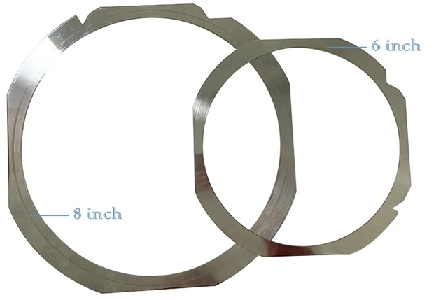
For hard ceramics, sapphire, and thick substrates, stronger adhesives such as thermal-release tape are necessary, and the saw must offer robust, high-vacuum chucks capable of keeping the substrate rigid under higher cutting forces. In R&D, or when working with odd geometries or non-standard shapes, the saw should include options for wax-mounting plates or flat vacuum chucks, which allow more flexibility than tape-based systems.
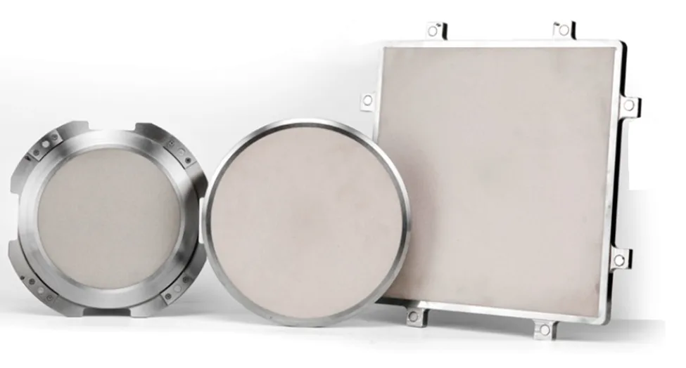
Machine design also plays a role. A high-quality dicing saw should provide multi-zone vacuum chucks to maintain even pressure across large panels, as well as the option to quickly interchange chucks of different diameters to suit different material sizes. In production, this reduces setup time and ensures repeatability, while in R&D it allows one saw to process a wide variety of materials without compromise.
If the chuck diameter, type, or compatibility is not matched to your application, even the best blade will fail to perform consistently. For this reason, when evaluating a dicing saw, confirm that it supports the correct chuck size for your substrates, the proper vacuum or adhesive mounting method, and the flexibility to adapt to future material requirements.
7. Diamond Dicing Blade Compatibility
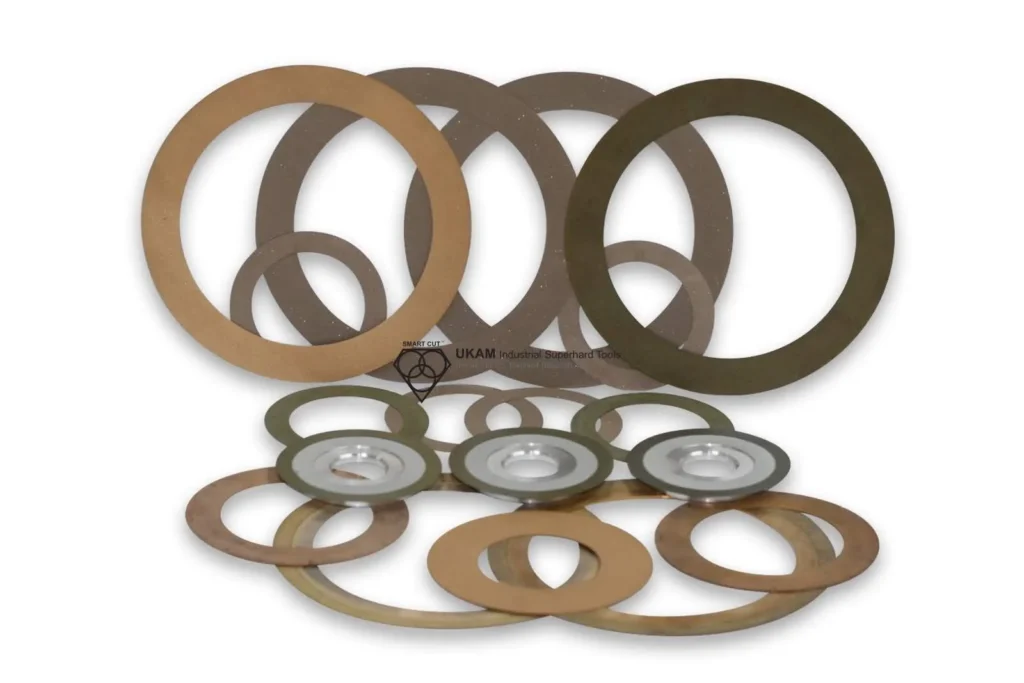
The diamond dicing blade is the most critical element in the wafer dicing process, as it directly engages with the substrate and determines the cutting speed, edge quality, kerf width, and overall efficiency of the operation. Several types of dicing blades are commonly used, each with specific strengths and trade-offs depending on the material and production requirements.
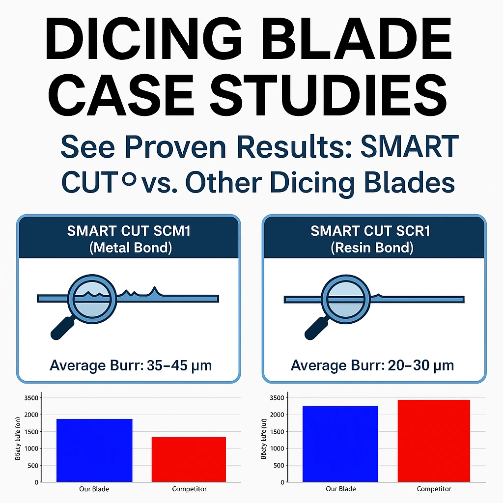
Resin bond dicing blades are known for their sharp, free-cutting action and ability to produce a very fine surface finish. They are widely used for delicate and brittle materials such as optical glass, quartz, and thin semiconductor wafers. Resin bonds naturally release worn diamond particles, exposing new cutting edges, which helps minimize chipping. Their drawback is a shorter blade life compared to metal bond blades, and they require effective cooling to prevent bond degradation under high temperatures.
Metal bond dicing blades are valued for their durability, long service life, and dimensional stability. The diamonds are held firmly in a metallic matrix, usually bronze or copper alloys, which makes them ideal for very hard substrates like sapphire, silicon carbide, zirconia, and alumina ceramics. While they deliver excellent consistency, they typically cut slower and with higher cutting forces than resin bonds, which can lead to chipping if feed rates and spindle speeds are not carefully controlled.
Hybrid bond dicing blades combine the sharpness of resin bonds with the longevity of metal bonds. They are designed for applications where both cutting speed and surface finish are important. These blades are especially effective when cutting advanced ceramics, semiconductor packages, and composites, where material hardness may vary. By balancing blade life with cut quality, hybrids reduce the need for frequent tool changes.
Electroplated (nickel bond) dicing blades are manufactured with a single layer of diamond particles bonded to the blade’s rim by a nickel matrix. This construction provides an extremely aggressive and precise cutting action, making them indispensable for thin kerf applications and high-precision cutting of hard, brittle materials such as sapphire, quartz, ceramics, and composites. Because the diamonds cannot self-renew, these blades have a shorter lifespan than resin or metal bonds. Still, they remain the blade of choice for research, prototyping, and specialized production runs where yield and cut accuracy outweigh blade longevity.
In addition to bond types, diamond dicing blades differ in their structural design. Hubbed blades are permanently mounted on a rigid metal hub, which improves stability, reduces runout, and simplifies installation. They are preferred for high-precision applications where vibration must be minimized. Hubless blades, mounted with separate flanges or spacers, are more flexible in size and thickness and are generally less costly, but they require careful mounting to maintain alignment and performance.
Another distinction is between continuous rim dicing blades and slotted rim/edge dicing blades. Continuous rim blades provide a smooth, uninterrupted cutting edge, producing clean cuts with minimal chipping, and are best for thin, fragile materials where surface quality/minimum chipping livel is critical. Slotted rim or edge blades incorporate small slots along the rim, which enhance coolant penetration, reduce heat buildup, and lower cutting resistance. They are advantageous when cutting thicker or harder substrates, though they may produce slightly rougher edges compared to continuous rim.

Selecting the correct diamond dicing blade type requires careful consideration of substrate properties, material thickness, desired kerf width, and required cut quality. No single blade type is universally best; the blade must be matched to the application and integrated into an optimized dicing system for consistent, high-yield results.
4.2 Blade Variables
When selecting a dicing saw, the blade variables must be matched with the machine’s design, spindle capabilities, and rigidity. A dicing blade is not chosen in isolation – it must work as part of a complete system.
The diamond grit size affects both the cutting force and surface finish, which in turn determines the required spindle power and feed control of the saw. For example, a fine-grit blade for precision cuts requires a saw with high positional accuracy and low runout, while a coarse-grit blade for fast cutting needs a machine with higher torque and rigidity to handle the increased cutting forces.
Diamond concentration and distribution dictate the load that the machine must sustain. High-concentration blades cut more aggressively, but they also require a saw with greater spindle stability and torque delivery. A low-concentration blade may cut with less force, allowing use on lighter-duty machines, but at the expense of throughput and blade life.
Blade thickness and exposure height tie directly to saw rigidity and alignment. Thinner kerf blades maximize yield but are fragile and demand a saw with very low vibration, excellent flange support, and precise alignment. A blade with greater exposure height requires a saw with stronger rigidity and spindle stiffness to prevent deflection.
Finally, flange design and mounting must be compatible with the saw. Some machines are designed specifically for hubbed blades, while others accommodate hubless designs with flanges and spacers. The size and quality of the flanges available on the saw will determine how effectively the blade runs.
8. Dicing Saw Size
The size of the dicing saw is one of the most practical but often underestimated factors when selecting equipment. The saw must be chosen to match the work envelope to the parts you plan to process, otherwise even a high-performance spindle and blade cannot deliver consistent results.

Begin by confirming the X, Y, and Z travel of the machine against your largest substrates and street maps. The saw should accommodate the maximum wafer or panel size, as well as the tape frame diameter and chuck format used in your process. Common requirements include 2 to 12 inch wafers and 6 to 12 inch frames, but specialized applications may require larger panel handling. If the machine cannot fully traverse the substrate or frame, production flexibility will be limited.
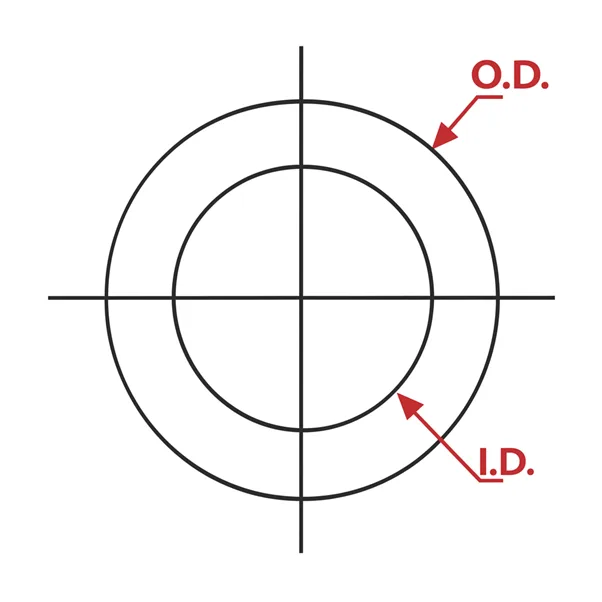
Blade compatibility is another key dimension. Verify the maximum blade outside diameter that the spindle and safety guards can accept. Many dicing applications use 2 to 6 inch diamond dicing blades, but certain thicker or larger substrates may require larger diameters. The saw must also support the appropriate blade thickness range and maximum safe exposure height without compromising rigidity. In addition, the flange diameter and stiffness must be validated.


The machine footprint and weight must be considered in the context of your facility. Benchtop dicing saws save space and are suited for R&D, prototyping, and occasional use, but they require careful vibration isolation to maintain accuracy. Floor-standing units provide greater mass, rigidity, and thermal stability, making them better suited for production environments and larger wafers or panels. Utilities must also be evaluated: confirm the need for clean dry air if the saw uses air-bearing spindles, as well as stable electrical supply, adequate coolant delivery, and return capacity.
9. Dicing Saw Optics and Vision
The optics and vision system of a dicing saw has a direct impact on alignment accuracy, setup speed, and overall yield. Even the most rigid machine and sharpest blade cannot perform consistently if the saw cannot properly recognize scribe lines, fiducials, or die patterns. For this reason, the quality of the vision package is a decisive factor when selecting a dicing saw.

At a minimum, the saw should be equipped with a high-resolution top camera that can be repeatedly calibrated to the spindle centerline. When cutting narrow streets or working with advanced semiconductor wafers, specify telecentric or low-distortion lenses, since these maintain dimensional accuracy across the field of view. Illumination is equally important. The system should offer coaxial, ring, and side lighting so operators can clearly reveal different surface features such as metallization layers, etched scribe marks, or alignment fiducials.
For thinned wafers mounted on tape, a bottom-side camera becomes essential. This allows backside alignment through transparent carriers, ensuring that cuts line up with patterns on the opposite surface. Without backside alignment, yield loss can occur when die shift or wafer bowing misaligns the top and bottom features.Modern systems should also include repeatable autofocus or laser-based height sensing, which maintains consistent edge sharpness and image quality even on warped wafers or non-uniform surfaces. In production environments, these features reduce operator intervention and minimize errors.
Automation within the vision system is another key factor. The saw should support automatic fiducial recognition, scribe line tracking, and kerf measurement, reducing reliance on manual alignment. Advanced software integration allows for street mapping, die shift compensation, and real-time path correction, ensuring that even if the wafer shifts slightly on tape or during processing, the saw can still cut with high accuracy.
In practice, a well-designed optics and vision package significantly reduces setup time, prevents miscuts, and raises first-pass yield. For R&D and occasional use, flexibility and ease of use are most important, operators need to quickly reconfigure optics for different materials. For full-scale production, speed and automation take priority, with features like pattern recognition, auto-focus, and SPC-linked vision checks ensuring high throughput and consistency.
10. Dicing Saw Operator Interface
The operator interface is the bridge between the user and the dicing saw, and it directly affects how efficiently the machine can be set up, monitored, and maintained. When evaluating dicing saws, it is important to remember that hardware performance alone is not enough, a poorly designed interface can waste time, increase error rates, and limit productivity, regardless of spindle power or system rigidity.
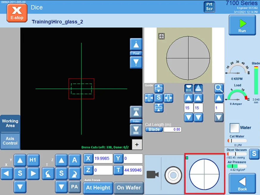
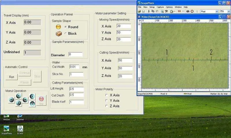
A modern dicing saw should feature a graphical interface with touchscreen controls that allows operators to quickly set and adjust spindle speed, feed rate, cut depth, coolant flow, and blade parameters. The interface should also provide real-time monitoring of spindle load, motor current, coolant pressure, and temperature, helping operators prevent process drift and detect early signs of tool wear or system instability.
Integration with the saw’s vision and optics package is equally critical. The interface should support automatic fiducial recognition, scribe line mapping, kerf offset adjustments, and die shift compensation directly from the control panel. These features reduce setup time, minimize human error, and raise first-pass yield by ensuring precise alignment without requiring constant operator intervention.
In production environments, the interface must go beyond basic controls. It should support data logging, statistical process control (SPC), and connectivity to manufacturing execution systems (MES). These functions allow engineers to track yield trends, optimize blade life, and integrate dicing data into broader factory workflows. Remote monitoring and diagnostic tools are also valuable, giving supervisors visibility into machine performance without being physically present.
Ease of training is another key factor. An intuitive, user-friendly interface reduces the learning curve for new operators and ensures consistent operation across multiple shifts. Systems with clear menus, recipe-driven process management, and automated calibration routines not only improve productivity but also reduce reliance on highly specialized personnel. This is especially important in high-volume fabs where staff turnover is common and downtime is costly.
In practice, the right dicing saw combines powerful, stable hardware with a well-designed operator interface that simplifies setup, speeds alignment, and provides robust monitoring and automation features. When choosing a system, confirm that the interface offers the right balance of simplicity for R&D and prototyping and advanced integration for mass production, ensuring that the machine remains both efficient and scalable as your needs evolve.
Dicing Saw total cost of ownership (TCO)
When evaluating a dicing saw, it is essential to consider the total cost of ownership (TCO) rather than focusing solely on the initial purchase price. A lower-cost machine may appear attractive at first but can become far more expensive in operation if it requires frequent downtime, has limited local support, or consumes consumables at a high rate. The true operating cost per cut is shaped by many ongoing factors, and these should be reviewed in detail before making a decision.

The first major element is consumables, which include diamond dicing blades, coolants, and filtration media. Blades wear out at different rates depending on the machine’s rigidity, spindle design, and coolant delivery, so a less stable machine may actually consume blades faster and increase operating cost. Coolant quality and filtration also affect blade life and cut quality, meaning that poor fluid management leads to higher consumable usage.
Next are spare parts and preventive maintenance. A well-designed production saw may cost more upfront but will often deliver longer intervals between servicing, predictable replacement schedules, and easier access for maintenance. On the other hand, a low-cost system may suffer from irregular failures, longer lead times for parts, or expensive downtime while waiting for service.
Another consideration is operator training and software usability. Machines with intuitive control software, recipe management, and automated alignment features reduce training time and minimize user error, improving both throughput and yield. Some systems require separate software licenses or feature upgrades for advanced functions, so these should be factored into long-term cost planning.
Finally, service response and local support availability directly influence uptime. If your machine requires frequent specialist intervention and there is no local service presence, downtime can quickly erase any savings from a lower purchase price. Reliable manufacturers and distributors provide fast response times, remote troubleshooting, and access to replacement parts, which helps ensure stable production.
By prioritizing uptime, yield, and support infrastructure over the lowest possible price, you gain control over your true per-cut cost and reduce the risk of costly interruptions. A careful TCO analysis often reveals that the machine with the higher initial price delivers a far lower long-term operating cost and a more predictable return on investment.
The System Approach
Successful wafer dicing must always be approached as a system of interacting components, not as a collection of isolated parts. A dicing process is only as strong as its weakest link. The machine, blade, mounting method, coolant system, and operating parameters form an interdependent network, where each element influences the others. If one component is mismatched or neglected, it can undermine the performance of the entire setup, even when all other variables are properly chosen.

A right diamond dicing blade will fail to deliver results if the machine lacks rigidity, if the flanges are improperly sized, or if the coolant system does not provide sufficient flow and coverage. At the same time, a basic or lower-cost blade can still achieve acceptable results when integrated into a balanced, stable, and well-optimized system. This principle makes it clear why the system approach is the foundation of effective dicing equipment selection.
The system approach also emphasizes that adjustments should be evaluated holistically. For instance, increasing spindle speed to boost throughput may overload the power capacity, cause the blade to overheat without adequate cooling, or amplify vibration issues in the mounting setup. Similarly, switching to a finer grit blade for better surface finish may demand adjustments in feed rate, coolant pressure, and mounting method to prevent chipping. Each change must be considered in relation to all other factors.
Another critical insight from the system perspective is that simple corrections often solve complex problems. Operators sometimes misdiagnose blade failure when the true cause lies in coolant nozzle positioning, mounting stress, or flange wear. A relatively small adjustment such as optimizing coolant delivery or replacing worn flanges, can restore efficiency and extend blade life dramatically. Case studies have shown that such changes can increase throughput by up to ten times without the need for new equipment or blades.
In practice, this means that before investing in new machinery or high-end blades, users should first analyze whether the entire system is optimized. A balanced system with correct rigidity, power, cooling, precision of motion, workpiece stability, blade compatibility, and environmental control will consistently deliver higher yields and lower costs. Viewing wafer dicing as a complete system rather than a set of parts is therefore the key to achieving predictable, repeatable, and economical results.


