


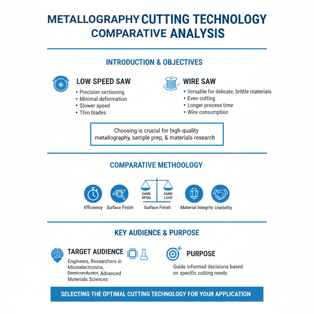
Comparing Two Different Cutting Methods (Low Speed Saw vs. Wire Saw)


-
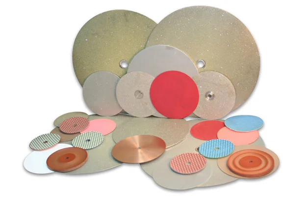
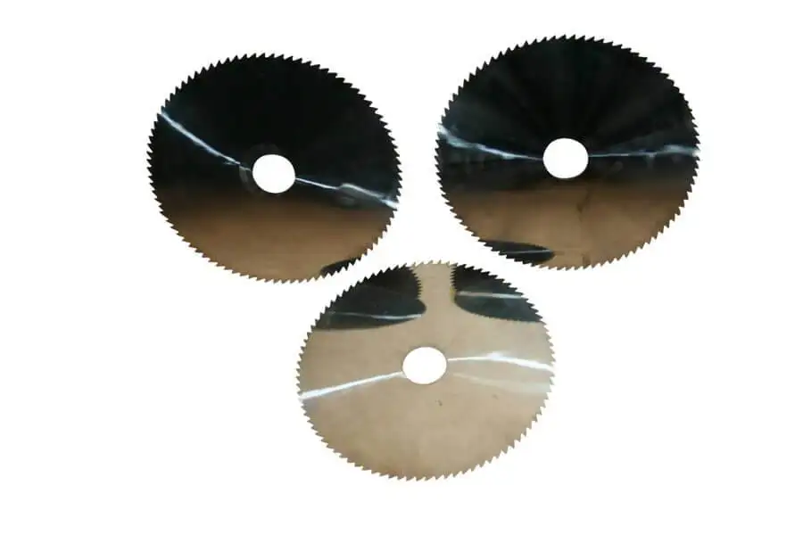
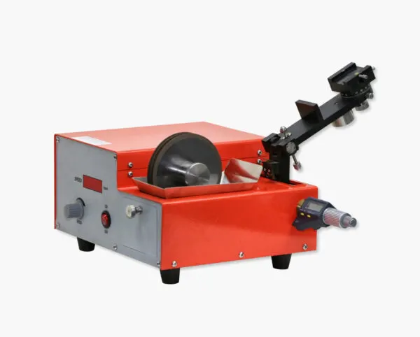
 Low-Speed Saw Cutting: This method uses various types of diamond wafering blades, known for precision and minimal material loss.
-
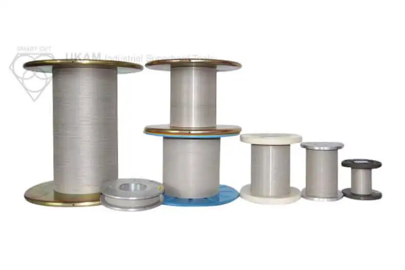
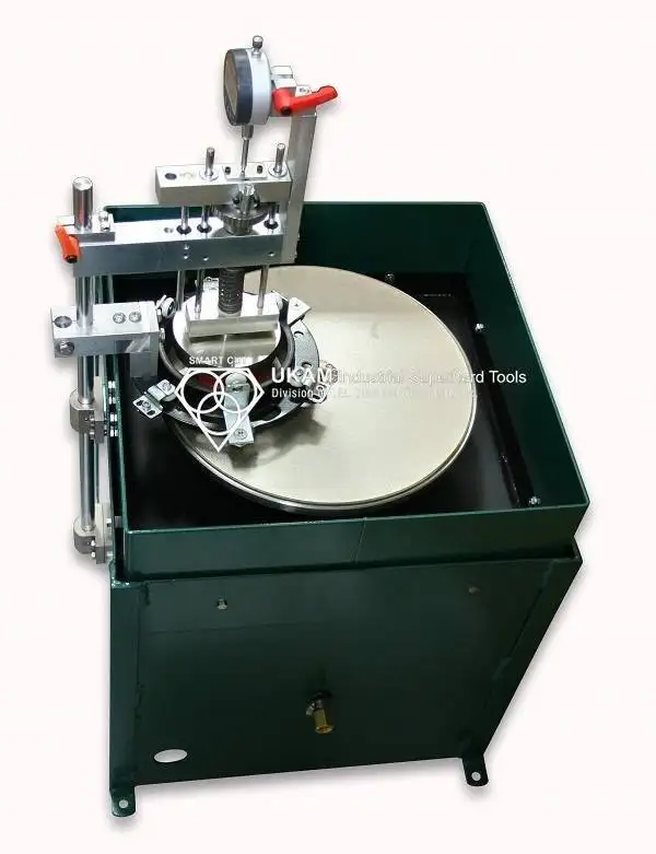
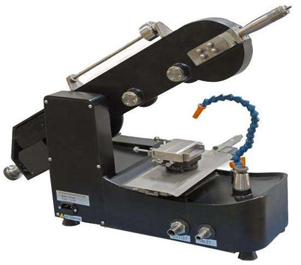
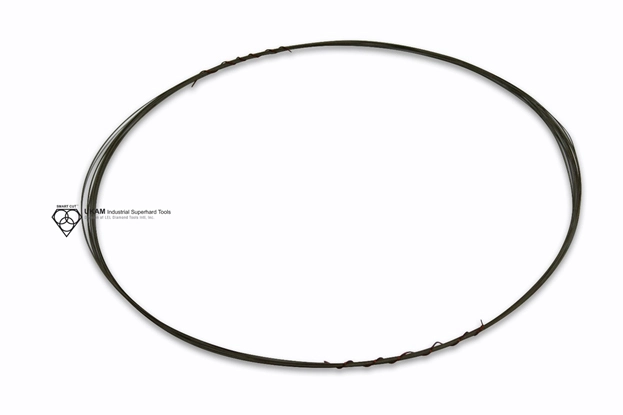
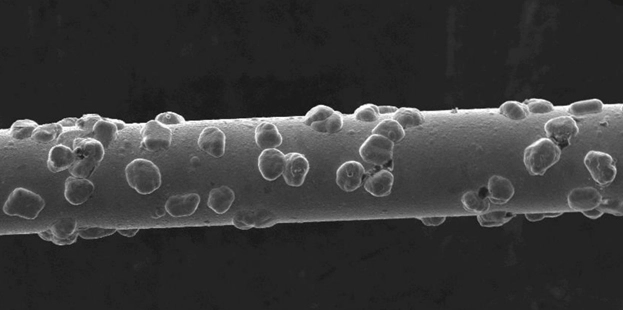
Wire Saw Cutting: This technique utilizes a wire embedded with abrasive particles, suitable for intricate cuts that require minimal mechanical stress on the material.
-
Surface Finish: Checked visually and through microscopy for any sub-surface damages or irregularities.
-
Edge Retention: Measured for sharpness and integrity, noting any deviations or chipping.
-
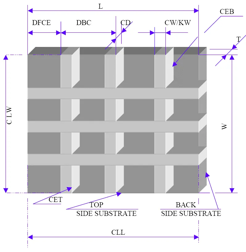
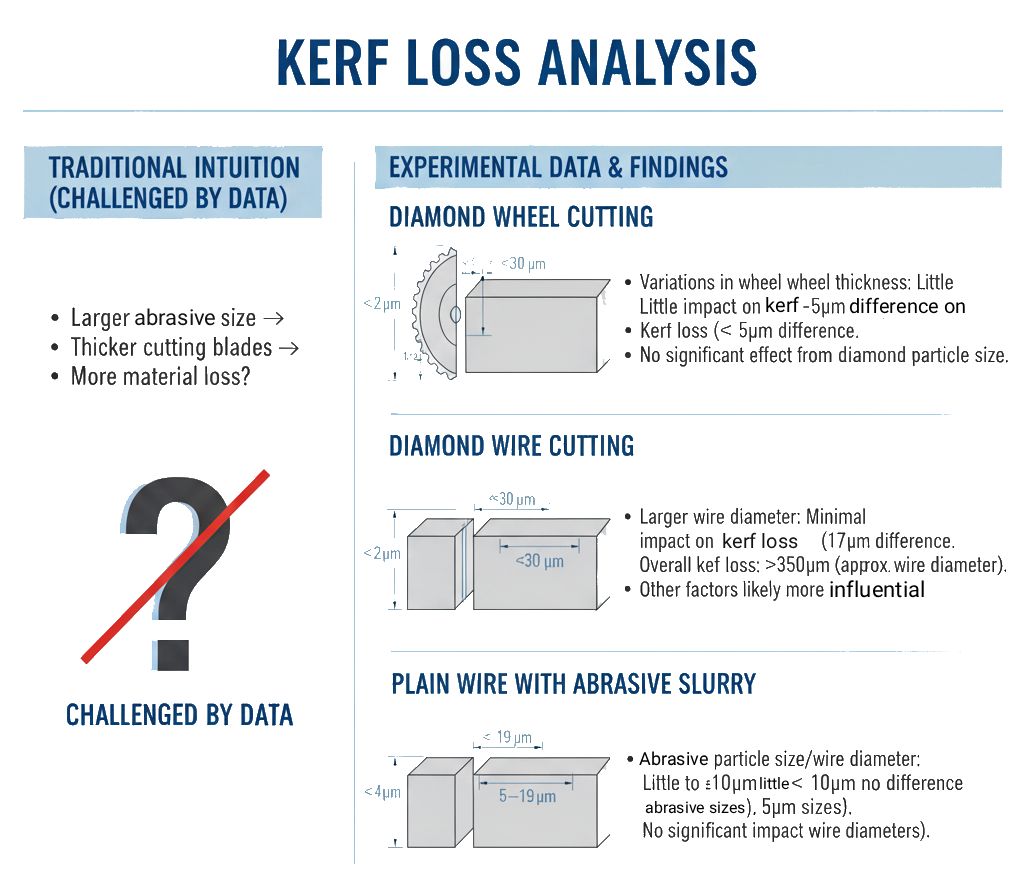
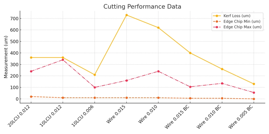
Cut Quality: Assessed for overall cleanliness, kerf width, and material loss.
-
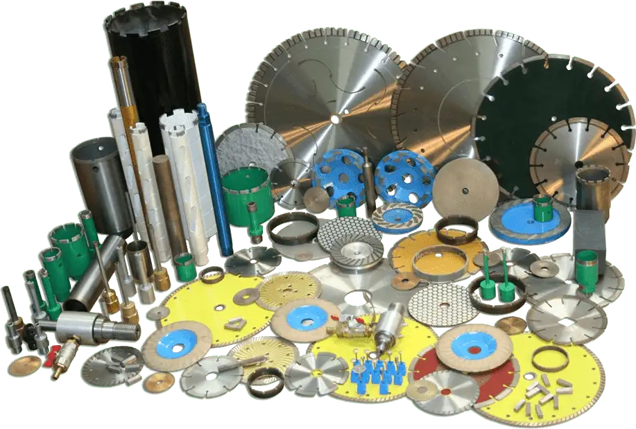
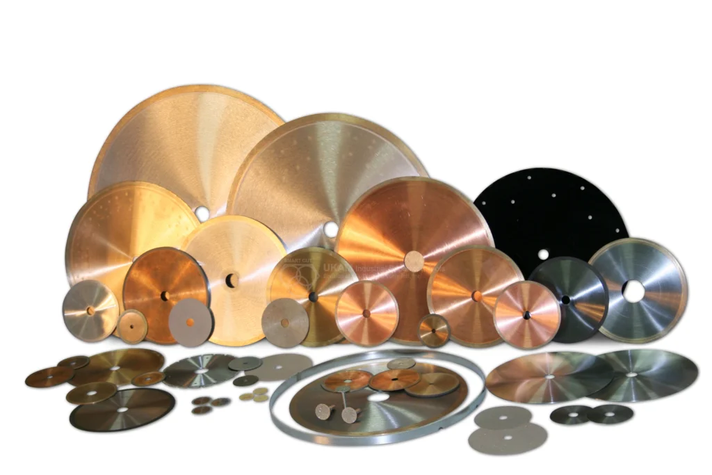
1. SiC Abrasive Wheel (4"): Known for its robust cutting capabilities.
-
2. Diamond Wheel, Fine Diamond Size, Low Concentration (10LCU): Designed for precise cuts with minimal kerf and excellent surface finish.
-
3. Diamond Wheel, Medium Diamond Size, High Concentration (15HCU): Balances cut quality with durability, suitable for moderate to tough materials.
-
4. Diamond Wheel, Coarse Diamond Size, High Concentration (20HCU): Best for rapid material removal with less emphasis on surface finish.
-
Load: 120 grams
-
Wheel Speed: 350 rpm
-
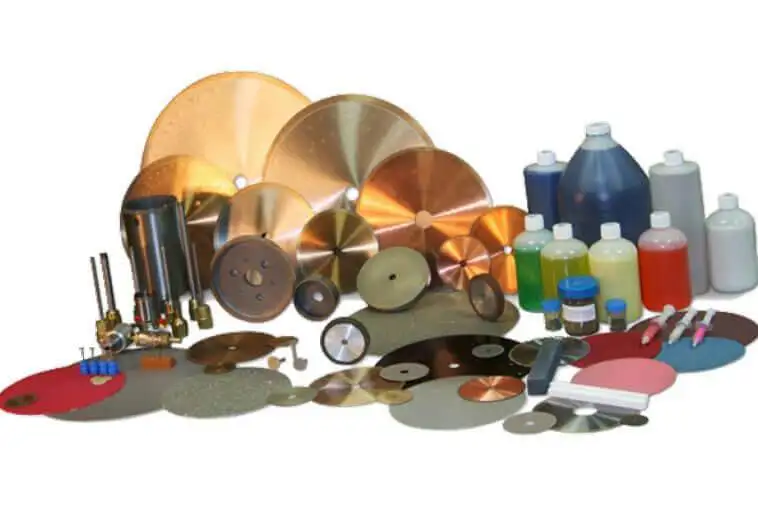
1. Al2O3 Slurry (22-micron Abrasive Size): Offers a standard cutting experience with moderate surface quality.
-
2. Silicon Carbide (SiC) Slurry (14-micron Abrasive Size): Provides a slightly smoother cut due to the finer abrasive size.
-
3. Boron Carbide (BC) Slurry (22-micron Particle Size): Tough and aggressive, suitable for more robust cutting applications.
-
4. Diamond Slurry (15-micron Particle Size): Delivers the finest cuts with superior surface finish and minimal damage.
-
Load: 120 grams
-
Wire: 0.010" stainless steel
-
Speed: 350 rpm
-
Slurry: Automatically applied
-
Low-Speed Saw Cuts: Demonstrated excellent control over cut quality with fine and medium diamond wheels, suggesting their use in applications requiring high precision and minimal surface damage.
-
Wire Saw Cuts: Showed variability based on slurry type, with diamond slurry outperforming others in terms of achieving a high-quality finish and maintaining material integrity.
-
Diamond Wheels: The use of diamond wheels with varying grit sizes demonstrates a clear impact on the quality of cuts. Fine diamond wheels (10LCU) provide excellent surface finishes with minimal chipping, indicating a high suitability for precision applications where surface integrity is paramount.
-
SiC Abrasive Wheel: Offers good performance, but may not achieve the superior finish provided by finer diamond grits, suggesting its use in less critical applications where a slightly lower surface quality is acceptable.
-
Diamond Slurry (15 micron): Shows better outcomes in terms of surface finish and minimal chipping compared to other slurries, reinforcing diamond's superiority in precision cutting applications.
-
Al2O3 and SiC Slurries: Provide satisfactory to poor finishes with varying degrees of chipping. These might be chosen for less delicate operations or where cost considerations override the need for a perfect finish.
-
Boron Carbide (BC) Slurry: Tends to perform less well, possibly due to its particulate properties affecting the smoothness of the cut, suggesting its use might be more situational depending on the specific material properties of the specimen.
-
The uniform load (120 grams) and speed (350 rpm) across tests simplify the comparison of cutting media effects, isolating the medium itself as the primary variable affecting outcomes.
-
These conditions seem adequate for both saws, as they allow for consistent application and evaluation of different cutting media, though adjustments might be necessary depending on specific material sensitivities or cutting requirements.
-
Material-Specific Tailoring: Further refinements in wheel and slurry selection should consider the specific material properties of the specimens being cut. For optical ferrules, where precision is critical, finer diamond grits and optimized slurry formulations could enhance outcomes.
-
Parameter Adjustments: Experimenting with varying loads and speeds could further optimize the cutting process, potentially reducing defects like chipping and improving overall efficiency.
-
Further Testing: Continued testing with a broader range of materials and more granular adjustments to cutting parameters could help in developing a more comprehensive understanding of the best practices for each type of cutting tool and material.

Brian is an experienced professional in the field of precision cutting tools, with over 27 years of experience in technical support. Over the years, he has helped engineers, manufacturers, researchers, and contractors find the right solutions for working with advanced and hard-to-cut materials. He’s passionate about bridging technical knowledge with real-world applications to improve efficiency and accuracy.
As an author, Brian Farberov writes extensively on diamond tool design, application engineering, return on investment strategies, and process optimization, combining technical depth with a strong understanding of customer needs and market dynamics.

How to Selecting Right Diamond Tools for your application

How to properly use Diamond Tools

Why use diamond

Diamond vs CBN (cubic boron nitride) Tools
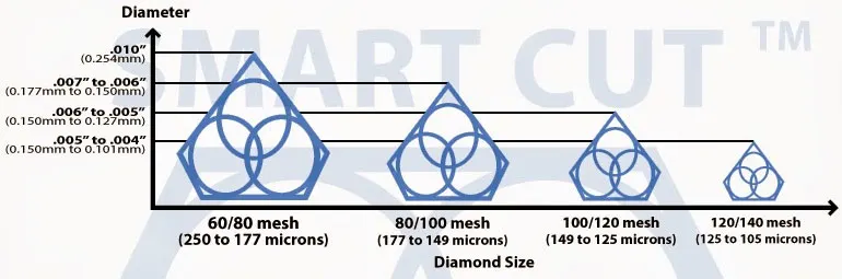
What is Diamond Mesh Size and how to select best one for your application

What is Diamond Concentration and which to use for your application

Choosing The Correct Diamond Bond Type
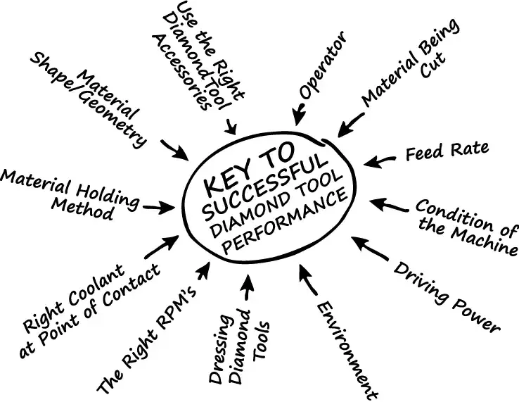
How to Properly Use Diamond Tools: A Complete Guide to Performance, Safety, and Tool Life
Brian is an experienced professional in the field of precision cutting tools, with over 27 years of experience in technical support. Over the years, he has helped engineers, manufacturers, researchers, and contractors find the right solutions for working with advanced and hard-to-cut materials. He’s passionate about bridging technical knowledge with real-world applications to improve efficiency and accuracy.
As an author, Brian Farberov writes extensively on diamond tool design, application engineering, return on investment strategies, and process optimization, combining technical depth with a strong understanding of customer needs and market dynamics.