






















Why Diamond Core Drills Fail Prematurely and How to Extend Tool Life

Table of Contents
Toggle
American Based Manufacturer

Established in 1990


Custom manufacturing


Introduction
Premature diamond core drill failure increases tooling costs, interrupts production, and creates dimensional inconsistencies in precision drilled components. In applications involving alumina, silicon carbide, sapphire, quartz, glass, and other hard or brittle materials, incorrect drill specifications can produce rapid abrasive wear, excessive edge chipping, bore taper, and inconsistent hole dimensions.
Replacing a worn drill without identifying the actual failure mechanism rarely solves the problem. A drill that loses cutting efficiency after a limited number of holes may have unsuitable bond hardness, inadequate diamond exposure, incorrect wall thickness, or insufficient coolant delivery. In other cases, excessive spindle runout, poor workpiece support, and inappropriate feed conditions are responsible.
For manufacturing engineers, the objective is not simply to purchase a drill with a longer advertised service life. It is to maintain a stable drilling process that produces acceptable holes at a predictable cycle time and cost.
Extending diamond core drill life requires evaluating the relationship between abrasive selection, bond wear, drill geometry, machine condition, coolant delivery, and workpiece properties.
This article examines the principal causes of premature diamond core drill failure and presents practical methods for diagnosing wear, selecting specifications, and qualifying tooling for production.
Why Diamond Core Drills Fail Prematurely
Diamond core drills remove material through the abrasive action of exposed diamond particles. The bond system retains these particles while controlled bond wear exposes fresh cutting edges.
Premature failure occurs when abrasive exposure, grain retention, bond wear, and operating conditions become unbalanced.
Common drilling problems and their causes
|
Observed problem |
Probable engineering cause |
Production consequence |
|---|---|---|
|
Drill stops cutting efficiently |
Glazing or inadequate diamond exposure |
Increased cycle time |
|
Rapid diamond loss |
Bond too soft or inadequate grain retention |
Shortened tool life |
|
Excessive heat generation |
Poor coolant delivery or excessive friction |
Accelerated wear |
|
Oversized holes |
Spindle runout or drill deflection |
Dimensional rejection |
|
Entry and exit chipping |
Excessive mechanical loading or inadequate support |
Component damage |
|
Uneven cutting face |
Misalignment or nonuniform loading |
Inconsistent drilling |
|
Drill body fracture |
Mechanical overload or insufficient structural strength |
Tool breakage |
|
Core jamming |
Insufficient internal clearance or poor debris evacuation |
Increased torque and damage |
Engineers should distinguish between abrasive wear, bond failure, and mechanical damage before changing the drill specification.
For example, increasing bond hardness may reduce diamond pullout, but it will not correct excessive spindle runout. Similarly, reducing feed may improve edge quality without correcting a glazed cutting surface.
Engineering principle: Identify the physical failure mechanism before changing the tooling specification.
Baseline Data Engineers Should Collect Before Changing Tooling
A tooling change should begin with documented production conditions. Without a baseline, engineers cannot establish whether a replacement drill actually improves performance.
Record the existing drill specification, machine settings, workpiece properties, and quality results before introducing a different abrasive configuration.
Baseline drilling documentation
|
Parameter |
Information to record |
Engineering purpose |
|---|---|---|
|
Drill stops cutting efficiently |
Exact grade and composition |
Establish material characteristics |
|
Material hardness |
Measured or specified hardness |
Determine abrasive requirements |
|
Workpiece thickness |
Actual component thickness |
Establish drilling depth |
|
Hole diameter |
Required and measured diameter |
Establish dimensional acceptance |
|
Hole depth |
Through hole or blind hole |
Determine debris evacuation requirements |
|
Drill outside diameter |
Actual OD |
Establish hole cutting geometry |
|
Drill inside diameter |
Actual ID |
Determine core clearance |
|
Wall thickness |
Actual drill tube thickness |
Evaluate rigidity |
|
Bond type |
Identify abrasive retention mechanism |
|
|
Diamond grit |
Mesh size or micron specification |
Evaluate cutting action |
|
Diamond concentration |
Manufacturer specification |
Establish abrasive distribution |
|
Spindle speed |
RPM |
Establish rotational conditions |
|
Feed rate |
mm/min |
Establish programmed feed |
|
Coolant |
Type, flow and delivery method |
Control heat and debris |
|
Spindle runout |
Measured TIR |
Identify alignment problems |
|
Tool life |
Acceptable holes per drill |
Measure usable tooling life |
|
Hole quality |
Diameter, taper, chipping and finish |
Establish acceptance criteria |
Inspect the worn drill before replacement
Inspection of the cutting section provides evidence about the mechanism responsible for premature failure.
|
Drill condition |
Likely interpretation |
Inspection requirement |
|---|---|---|
|
Smooth, polished cutting surface |
Possible glazing |
Examine diamond exposure |
|
Missing diamond particles |
Excessive grain pullout |
Inspect bond retention |
|
Uneven abrasive wear |
Nonuniform loading |
Check spindle runout |
|
Cracked drill tube |
Mechanical overload |
Examine mounting and drilling loads |
|
Heavy debris accumulation |
Inadequate flushing |
Inspect coolant delivery |
|
Rounded or worn abrasive edges |
Progressive abrasive wear |
Compare cycle time and hole count |
Photograph the cutting face at consistent magnification after defined production intervals. Comparing these images helps distinguish normal abrasive wear from premature bond failure.
Six Major Causes of Diamond Core Drill Failure
Incorrect bond hardness
Bond hardness controls how effectively diamond particles remain attached during material removal.
An excessively hard bond can retain worn diamond particles instead of releasing them at the appropriate stage. The cutting surface gradually becomes polished, reducing effective cutting action.
An excessively soft bond releases diamond particles before their useful abrasive life is exhausted. This produces accelerated wear and reduces the number of acceptable holes per drill.
|
Bond condition |
Typical failure |
Corrective engineering direction |
|---|---|---|
|
Too hard |
Glazing and reduced cutting rate |
Evaluate a softer bond formulation |
|
Too soft |
Excessive diamond pullout |
Evaluate a harder bond formulation |
|
Properly matched |
Controlled abrasive exposure |
Maintain qualified process settings |
Bond selection must account for material hardness, abrasiveness, drilling depth, coolant conditions, and required cutting rate.
Incorrect diamond grit size
Diamond grit size determines the scale of individual abrasive engagement.
Coarser diamond particles generally provide greater penetration per grain. They can support higher material removal in suitable applications, but aggressive engagement may increase edge chipping and surface roughness.
Finer diamond particles provide smaller individual cutting actions and can support better surface quality. However, a finer specification may increase cutting resistance if the bond and operating parameters are unsuitable.
|
Selection factor |
Coarser diamond |
Finer diamond |
|---|---|---|
|
Individual grain penetration |
Higher |
Lower |
|
Surface finish |
Generally rougher |
Generally finer |
|
Material removal |
Often higher in suitable conditions |
Often lower at comparable conditions |
|
Edge quality |
Requires controlled engagement |
Can support reduced chipping |
|
Primary consideration |
Productivity |
Surface quality |
Grit selection should be based on required bore quality and actual drilling conditions, not on the assumption that finer or coarser diamond is always preferable.
Incorrect spindle speed and peripheral velocity
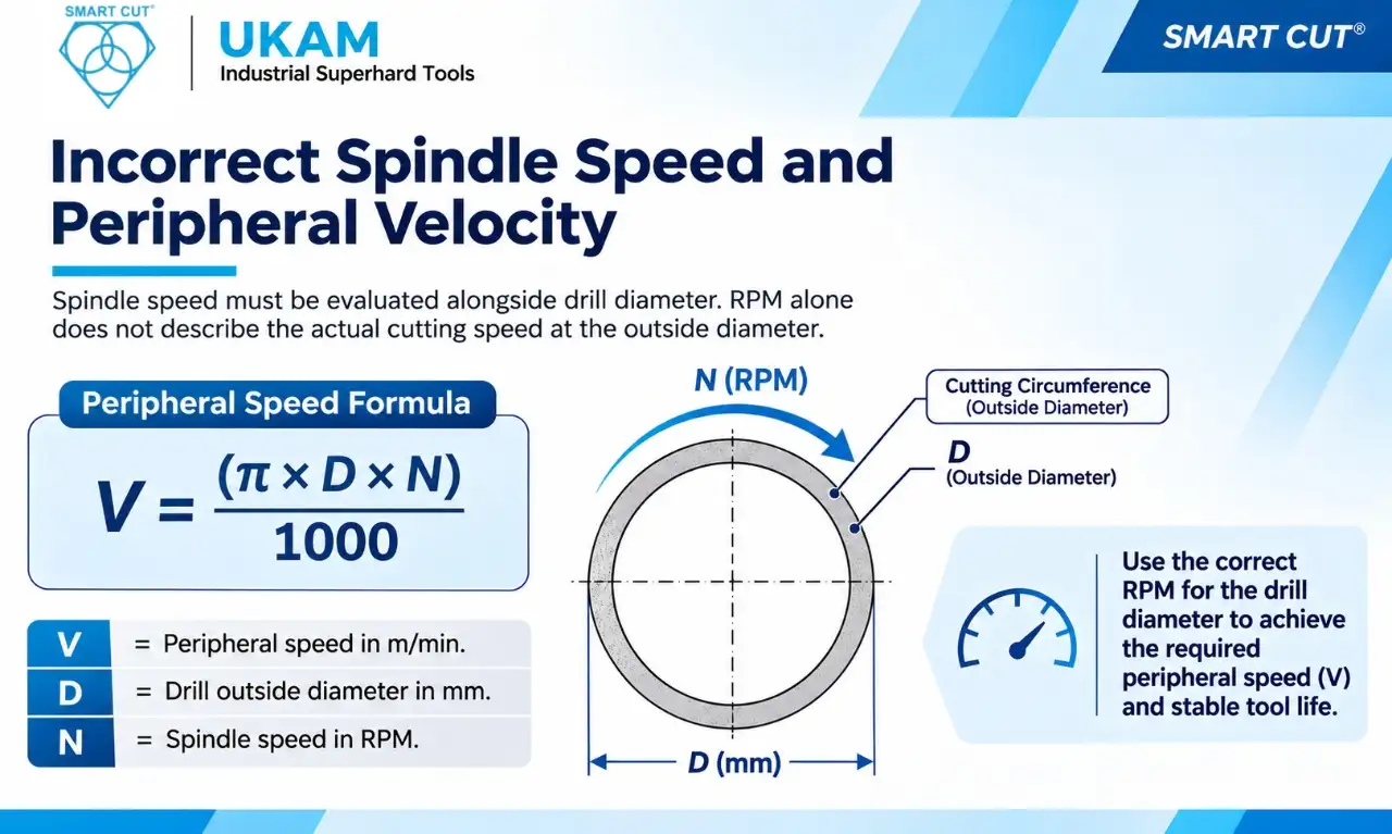
Spindle speed must be evaluated alongside drill diameter. RPM alone does not describe the actual cutting speed at the outside diameter.
Peripheral speed can be calculated using:
V = (π × D × N) / 1000
Where:
- V = Peripheral speed in m/min.
- D = Drill outside diameter in mm.
- N = Spindle speed in RPM.
For example, a 10 mm diamond core drill operating at 3,000 RPM produces a peripheral speed of approximately 94.2 m/min.
A 25 mm drill operating at the same RPM produces approximately 235.6 m/min.
The difference is significant even though both drills use identical spindle settings.
Excessive peripheral speed can increase friction, temperature, and abrasive wear. Operating below the suitable range can also reduce cutting efficiency. The operating window must be established according to drill construction, diameter, material, and coolant delivery.
Excessive feed rate and feed pressure
Feed rate and feed pressure are related, but they are not interchangeable.
Feed rate is the programmed or measured axial advancement of the drill, generally expressed in mm/min.
Feed pressure is the mechanical force applied along the drilling axis, generally expressed in newtons or measured through an appropriate machine load or force monitoring system.
A programmed feed rate does not establish a constant drilling force. Actual loading changes with material hardness, abrasive condition, drill geometry, machine rigidity, and drilling depth.
Excessive feed rate can increase mechanical loading, particularly during entry and breakthrough. Excessive axial force can also cause drill deflection, vibration, diamond damage, and brittle material fracture.
For sapphire, alumina, silicon nitride, and glass, engineers should monitor both programmed feed and actual machine loading.
Inadequate coolant and debris evacuation
Coolant performs three primary functions:
- Removes heat generated at the cutting interface.
- Flushes abrasive debris from the drilling zone.
- Reduces friction and prevents debris accumulation.
External flood cooling may provide sufficient fluid in some shallow drilling applications. However, it may not remove debris effectively from deeper holes or small diameter drills.
Through hole coolant can deliver fluid closer to the cutting interface when the drill is designed for that arrangement.
Debris accumulation increases cutting resistance and can cause localized heating, surface damage, and premature wear. Coolant flow, pressure, delivery direction, and filtration should therefore be included in process qualification.
Spindle runout and vibration
Spindle runout causes uneven engagement around the drill circumference.
When one side of the cutting face carries more load than the opposite side, abrasive wear becomes nonuniform. This can produce oversized holes, taper, vibration, and premature damage to the drill tube.
Measure radial runout near the mounting interface and, where accessible, near the cutting section. Check spindle bearings, collet condition, mounting threads, toolholder cleanliness, and workpiece fixture rigidity.
A drill specification should not be changed until machine alignment has been evaluated.
Drill Geometry: How Construction Influences Tool Life
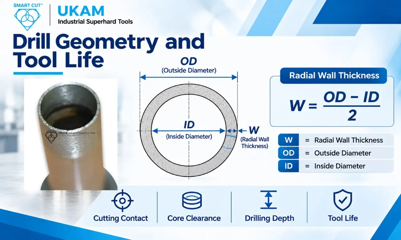
A diamond core drill is not defined by outside diameter and diamond grit alone. Its geometry determines cutting contact, structural rigidity, core clearance, drilling depth, and the ability to evacuate material.
These characteristics become particularly important when drilling small diameter holes, deep holes, and brittle materials with strict dimensional requirements.
Outside diameter and inside diameter
The outside diameter determines the nominal hole size, while the inside diameter determines the diameter of the retained core.
The difference between these dimensions defines the available radial cutting width.
W = (OD − ID) / 2
Where:
- W = Radial wall thickness.
- OD = Outside diameter.
- ID = Inside diameter.
For example, a drill with a 10 mm outside diameter and an 8 mm inside diameter has a nominal radial wall thickness of 1 mm.
Actual manufactured wall thickness and abrasive section geometry must also be considered.
Wall thickness and structural rigidity
Wall thickness affects drill strength and cutting contact.
|
Wall thickness consideration |
Engineering implication |
|---|---|
|
Thin wall |
Reduced material removal and cutting contact, but greater sensitivity to deflection |
|
Intermediate wall |
Balance between rigidity and cutting engagement |
|
Heavy wall |
Greater structural section, but potentially higher material contact and cutting resistance |
A thin wall drill may be appropriate where reduced kerf and material loss are priorities. A heavier construction may be more suitable where mechanical stability is critical.
Selection must consider diameter, unsupported length, drilling depth, machine rigidity, and workpiece properties.
Diamond depth versus drilling depth
These dimensions describe different characteristics.
Diamond depth refers to the axial height of the diamond abrasive section.
Drilling depth refers to the achievable workpiece penetration under the particular drill construction and operating conditions.
A longer diamond section does not automatically provide the same increase in usable drilling depth. Relief geometry, core clearance, and the available space behind the cutting section also influence drilling performance.
Core clearance and relief geometry
In hollow core drilling, the material inside the cutting diameter forms a cylindrical core.
The drill must maintain sufficient clearance between the core and internal drill wall. Insufficient clearance can cause friction, core jamming, and increased drilling torque.
Internal and external relief can also influence cutting resistance and debris movement.
|
Geometric feature |
Function |
Failure to monitor |
|---|---|---|
|
Internal relief |
Provides clearance around the core |
Core binding |
|
External relief |
Reduces unnecessary contact |
Excessive friction |
|
Wall thickness |
Supports drill structure |
Deflection |
|
Diamond section height |
Provides working abrasive depth |
Premature loss of usable cutting section |
|
Mounting interface |
Establishes concentricity |
Runout and vibration |
Drill concentricity and radial runout
Concentricity describes the relationship between the drill mounting axis and cutting geometry.
Radial runout is the measured variation in radial position as the drill rotates.
Excessive runout causes uneven cutting engagement, dimensional variation, and localized wear. It becomes particularly critical in small diameter drills, where minor deviations represent a significant proportion of the cutting width.
For precision applications, engineers should specify the required runout and dimensional tolerances in the tooling drawing rather than relying on nominal diameter alone.
Through Hole Versus Blind Hole Drilling
The drilling method influences coolant delivery, core removal, debris evacuation, and the mechanical loading experienced by the drill.
A specification that works for a shallow through hole may not perform consistently in a deeper blind hole.
Engineering comparison
|
Parameter |
Through hole drilling |
Blind hole drilling |
|---|---|---|
|
Drilling arrangement |
Drill penetrates the complete workpiece |
Drill stops at a specified depth |
|
Core removal |
Core can exit through the workpiece |
Core remains inside the drilled section |
|
Debris evacuation |
Generally easier when clearance is available |
More difficult as depth increases |
|
Coolant requirements |
Must reach the cutting interface and flush debris |
Requires effective fluid delivery and debris removal |
|
Main mechanical concern |
Exit breakout and breakthrough loading |
Core binding and debris accumulation |
|
Inspection priority |
Entry and exit edges |
Bore depth, bottom geometry and bore walls |
Through hole drilling considerations
The main concern is maintaining stable cutting conditions during entry and breakthrough.
When the drill approaches the opposite surface, the remaining material section becomes progressively thinner. Excessive feed loading at this stage can cause exit chipping, radial cracks, or breakout.
Engineers should evaluate workpiece support beneath the drilling area and establish a controlled breakthrough condition.
Blind hole drilling considerations
Blind hole drilling requires particular attention to core clearance and debris evacuation.
As the drill penetrates deeper, abrasive debris can accumulate inside the bore. The retained core can also become trapped if the internal clearance is insufficient.
For deeper blind holes, evaluate:
- Available internal coolant delivery.
- Core clearance and removal method.
- Drill length and unsupported section.
- Debris accumulation.
- Actual drilling depth versus abrasive section depth.
The drilling cycle should be qualified at the maximum required depth, not only on shallow test holes.
Material Specific Failure Modes During Diamond Core Drilling
Different materials produce different drilling loads, abrasive wear patterns, and fracture behavior. A drill specification that performs acceptably on glass may fail prematurely on silicon carbide.
Material qualification should include the exact grade, thickness, structure, and hole geometry.
Alumina ceramics
Alumina is a hard and abrasive ceramic used in electrical insulation, wear components, and industrial equipment.
Failure mode: Bond erosion and diamond pullout.
High abrasive loading can progressively wear the bond and reduce the effective cutting section. Excessive feed pressure can also produce entry and exit chipping.
Qualification considerations:
- Evaluate sintered metal bond hardness.
- Monitor abrasive retention and cutting face condition.
- Inspect bore diameter and edge chipping.
- Record drilling time at defined hole counts.
- Actual drilling depth versus abrasive section depth.
The root cause should be confirmed through inspection and controlled process adjustments.
Silicon carbide
Silicon carbide presents demanding drilling conditions because of its high hardness and abrasive characteristics.
Failure mode: Rapid abrasive wear and glazing.
A bond that retains worn abrasive particles for too long may reduce cutting efficiency. Poor coolant delivery can further increase friction and debris accumulation.
Qualification considerations:
- Evaluate sintered metal bond specifications.
- Check peripheral speed and axial loading.
- Monitor cutting time and machine load.
- Inspect the cutting face for glazing.
Silicon nitride
Silicon nitride is used in high performance bearings, mechanical components, and thermal applications.
Failure mode: Subsurface microcracking and edge breakout.
Its fracture behavior makes it sensitive to localized mechanical loading. Drill vibration and excessive feed can damage the bore even when the abrasive section remains serviceable.
Qualification considerations:
- Evaluate entry and exit surface integrity.
- Maintain rigid workholding.
- Inspect the bore wall under magnification.
- Record subsurface damage where component requirements demand it.
Sapphire
Sapphire is used in optical windows, electronic substrates, and precision optical components.
Failure mode: Edge chipping and subsurface cracking.
Crystal orientation, workpiece thickness, and drilling direction can influence the resulting surface damage.
Qualification considerations:
- Document material orientation where relevant.
- Select grit according to edge quality requirements.
- Control feed and spindle alignment.
- Inspect both entry and exit surfaces.
Fused silica and quartz
Fused silica and quartz are used in optical, laboratory, and semiconductor applications.
Failure mode: Radial cracking and exit breakout.
Localized mechanical loading, inadequate support, and thermal variation can produce cracks extending beyond the nominal hole boundary.
Qualification considerations:
- Evaluate the workpiece support arrangement.
- Control feed pressure near breakthrough.
- Control feed and spindle alignment.
- Check bore quality under magnification.
Glass and optical glass
Glass drilling requires controlled material removal without excessive damage to the surrounding surface.
Failure mode: Circumferential chipping and radial cracking.
Aggressive grain engagement and unstable workpiece support can damage the bore perimeter.
Qualification considerations:
- Evaluate suitable continuous rim and other cutting geometries.
- Select grit according to required finish.
- Control entry and breakthrough conditions.
- Monitor coolant flow and debris removal.
Gallium arsenide (GaAs)
GaAs is a brittle semiconductor material used in electronic and optoelectronic devices.
Failure mode: Edge fracture and subsurface damage.
Thin substrates are particularly sensitive to mechanical loading and inadequate support.
Qualification considerations:
- Verify substrate thickness and support.
- Control axial loading.
- Check for edge fracture.
- Inspect both surfaces for damage.
Tungsten carbide
Tungsten carbide is a hard composite material containing carbide grains and a metallic binder, commonly cobalt.
Failure mode: Uneven abrasive wear and localized loading.
Different carbide grades and binder contents can produce different machining behavior.
Qualification considerations:
- Identify carbide grade and binder composition.
- Evaluate bond retention.
- Monitor cutting resistance.
- Inspect for localized wear and bore deviation.
Polycrystalline diamond (PCD)
PCD consists of diamond grains consolidated into a polycrystalline structure, commonly supported by a cemented carbide substrate.
Failure mode: Localized chipping and interface damage.
The composite structure requires application specific tooling evaluation. PCD layer thickness and supporting substrate influence the drilling operation.
Qualification considerations:
- Record PCD grade and layer thickness.
- Document substrate construction.
- Inspect for localized fracture.
- Evaluate the diamond to substrate interface after drilling.
Material failure reference
|
Material |
Primary failure mode |
Critical acceptance measurement |
|---|---|---|
|
Alumina |
Bond erosion and diamond pullout |
Tool life and bore quality |
|
Silicon carbide |
Abrasive wear and glazing |
Cutting time and tool condition |
|
Silicon nitride |
Microcracking |
Bore integrity |
|
Sapphire |
Edge chipping |
Entry and exit quality |
|
Fused silica |
Radial cracking |
Surface integrity |
|
Quartz |
Exit breakout |
Exit edge condition |
|
Glass |
Circumferential chipping |
Bore perimeter |
|
GaAs |
Edge fracture |
Substrate integrity |
|
Tungsten carbide |
Uneven abrasive wear |
Bore dimensions |
|
PCD |
Localized chipping |
Interface condition |
A Step by Step Process to Extend Diamond Core Drill Life
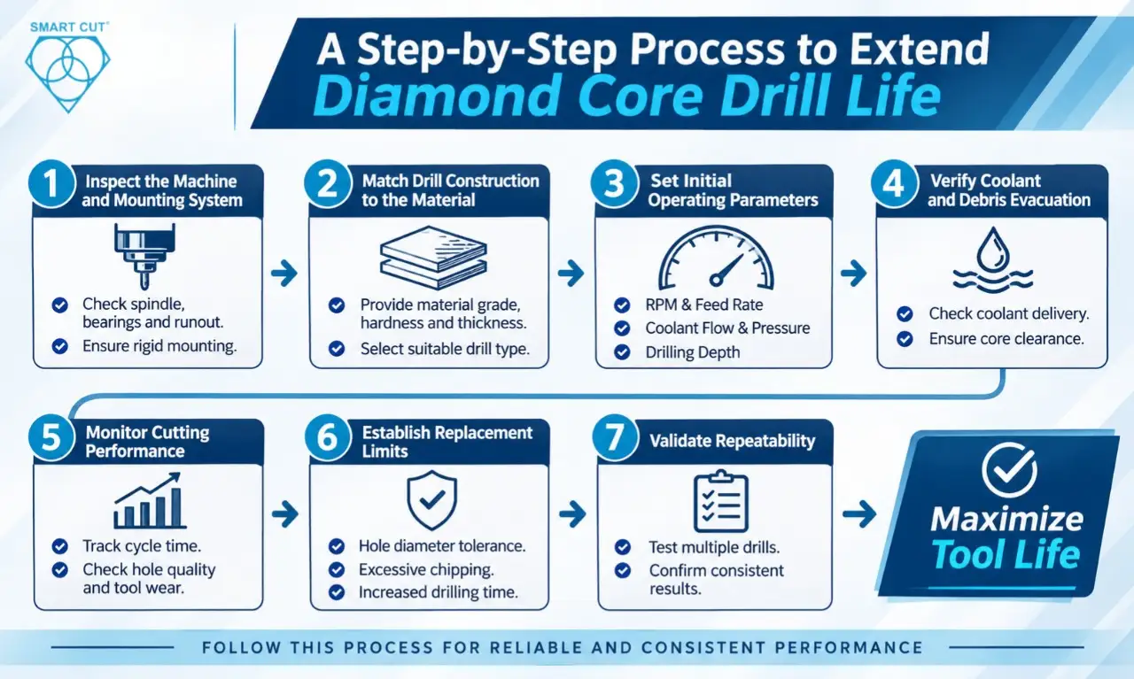
A repeatable qualification procedure allows engineers to identify which process variables influence tool performance.
Phase 1: Inspect the machine and mounting system
Before changing the drill, inspect the machine spindle, bearings, collet, mounting thread, and workholding system.
Measure radial runout close to the mounting interface. Confirm that the drill is mounted concentrically and that the workpiece cannot move under drilling load.
Phase 2: Match drill construction to the material
Provide the manufacturer with the exact material grade, hardness, thickness, hole diameter, and required drilling depth.
Determine whether the operation requires a hollow core drill, a bottoming configuration, a non core forming drill, or another specialized construction.
Phase 3: Establish initial operating parameters
Start with the manufacturer’s recommended operating window.
Do not change several parameters simultaneously. Adjust one variable at a time to identify its influence on cutting performance.
Phase 4: Verify coolant delivery and debris evacuation
Check that coolant reaches the active cutting zone.
For deep drilling, evaluate through hole coolant where the drill construction and machine permit it. Inspect internal clearance and confirm that the core can exit without binding.
Phase 5: Monitor cutting performance
Record cycle time, hole count, dimensions, and visible drill wear at defined production intervals.
A gradual increase in drilling time can indicate abrasive wear before the drill produces unacceptable holes.
Phase 6: Establish replacement limits
Define measurable replacement criteria rather than waiting for catastrophic failure.
Phase 7: Validate repeatability
Test multiple drills using the same approved operating conditions.
Compare acceptable holes per drill, dimensional consistency, cycle time, and total tooling cost. Approve the new specification only after repeatable results have been obtained.
Cost Per Acceptable Hole: Measuring Actual Drill Performance
A diamond core drill with a higher purchase price can produce a lower overall manufacturing cost if it delivers more acceptable holes, reduces cycle time, and lowers scrap.
Engineers should compare tooling using the complete cost of producing acceptable components rather than purchase price or advertised tool life alone.
Illustrative supplier comparison
The following example compares two diamond core drill suppliers producing 1,000 acceptable holes under equivalent production requirements.
Illustrative figures only. These are not actual UKAM performance results or supplier quotations.
The example assumes the stated tool life represents attempted holes per drill, including rejected components. The number of drills is rounded up to whole tools.
Dressing is shown as not required in this example. Where a particular drill construction requires dressing or conditioning, those costs should be added to the comparison.
Supplier B has a higher initial purchase price, but longer tool life, shorter cycle time, and lower scrap reduce the overall production cost.
Cp = (Ct + Cd + Cm + Cs) / Na
Where:
- Cp = Cost per acceptable hole.
- Ct = Total tooling cost.
- Cd = Total dressing or conditioning cost.
- Cm = Total machining cost.
- Cs = Total scrap cost.
- Na = Number of acceptable holes.
For an actual production assessment, use the same material grade, hole geometry, dimensional acceptance criteria, and production volume for every supplier.
What Engineers Should Ask a Diamond Core Drill Manufacturer
A tooling manufacturer should understand the drilling process before recommending a replacement specification.
An engineer evaluating a new supplier should request specific information about abrasive construction, drill geometry, manufacturing tolerances, and application support.
Supplier evaluation reference
Information to provide when requesting a custom drill
For a technically useful recommendation, prepare:
- Material name, grade, and hardness.
- Workpiece thickness.
- Required outside diameter.
- Required inside diameter or core diameter.
- Required drilling depth.
- Existing drill specification.
- Machine type and spindle speed.
- Coolant delivery arrangement.
- Required dimensional tolerances.
- Current failure symptoms and expected tool life.
A component drawing or photograph of the existing drill can help clarify mounting geometry and dimensional requirements.
SMART CUT® Diamond Core Drills: Comparing Available Constructions
UKAM Industrial Superhard Tools manufactures standard and custom diamond core drills under its SMART CUT® technology range.
Different constructions address different drilling requirements. Engineers should compare abrasive retention, drill geometry, available diamond depth, and material compatibility rather than selecting a drill based on product designation alone.
SMART CUT® construction comparison
Source: UKAM published product descriptions and specifications. Confirm current product drawings before ordering.
100DE SMART CUT® Series
Multi Layer Electroplated Diamond Core Drills
The 100DE series uses three diamond layers retained through a nickel alloy bond. Its published application range includes glass, quartz, optical materials, composites, and softer advanced materials.
The electroplated construction is not the recommended starting choice for ultra hard materials where a sintered metal bond is more appropriate.
115DE SMART CUT® Series
Sintered Metal Bond Diamond Core Drills
The 115DE series uses a sintered metal bond construction. Its published application range includes alumina, quartz, ruby, YAG, silica, silicon, graphite, and other nonmetallic ceramics.
The metal matrix retains diamond particles as the bond wears. Actual performance depends on the material, bond formulation, operating parameters, and drilling depth.
Custom SMART CUT® configurations
Standard drill dimensions do not always match production requirements. UKAM also offers custom diamond core drill configurations with different diameters, drilling depths, bond types, diamond grit sizes, mounting arrangements, and tolerances.
Published product configurations can contain different dimensions depending on drill size and construction. Engineers should confirm the actual OD, ID, wall thickness, diamond depth, drilling depth, and tolerances against the current product drawing or written quotation before ordering.
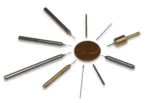
For specialized micro drilling, UKAM also publishes SMART CUT® micro and miniature sintered metal bond drill configurations with different grit sizes, diameters, and dimensional tolerances.
Diamond Core Drill Qualification Checklist
Use this checklist before approving a new drill specification for production.
Workpiece and application
- Confirm exact material grade and composition.
- Record material hardness.
- Document workpiece thickness.
- Define hole diameter and depth.
- Identify through hole or blind hole requirements.
- Establish entry and exit quality criteria.
Drill specification
- Verify outside and inside diameters.
- Confirm wall thickness.
- Select appropriate bond type.
- Confirm diamond grit size and concentration.
- Verify diamond depth.
- Check internal and external relief.
- Confirm mounting dimensions.
- Specify runout and dimensional tolerances.
Machine and process conditions
- Measure spindle runout.
- Verify spindle speed and peripheral velocity.
- Record feed rate and axial drilling force.
- Check coolant flow and delivery.
- Confirm workpiece support.
- Verify core clearance.
- Check debris evacuation.
Production qualification
- Establish baseline tool life.
- Conduct controlled drilling trials.
- Record cycle time per hole.
- Measure hole diameter and taper.
- Inspect entry and exit chipping.
- Examine the cutting face at defined intervals.
- Record acceptable holes per drill.
- Calculate cost per acceptable hole.
Production approval
- Validate performance across multiple drills.
- Confirm dimensional repeatability.
- Approve operating parameters.
- Define inspection intervals.
- Establish replacement criteria.
- Establish replacement criteria.
Frequently Asked Questions About Diamond Core Drills
Premature wear usually results from incorrect bond hardness, unsuitable diamond grit, excessive mechanical loading, inadequate coolant, or poor spindle alignment. Hard abrasive materials can accelerate bond erosion and diamond particle loss. Engineers should inspect the cutting face and measure machine runout before changing the tooling specification. The failure mechanism determines whether a different bond, abrasive size, or process adjustment is required.
Start by matching the bond system and diamond grit to the workpiece material. Maintain suitable spindle speed and feed conditions, provide coolant directly to the cutting zone, and prevent debris accumulation inside the drill. Monitor drilling time and dimensional accuracy at defined intervals. Replacing the drill based on measurable wear limits rather than waiting for complete failure can also prevent secondary damage to the workpiece.
Sintered metal bond diamond core drills are frequently considered for silicon carbide and alumina because their metal matrix retains diamond particles as the bond gradually wears. The exact bond hardness must be matched to the material grade and operating conditions. A bond that is too hard can glaze, while an excessively soft bond can release abrasive particles prematurely. Qualification trials should measure cutting rate, wear, and hole quality.
Electroplated diamond drills retain abrasive particles through a nickel plated layer deposited onto the drill surface. Sintered drills retain diamond particles within a metal matrix. Electroplated constructions are commonly considered for glass, quartz, optical materials, and suitable composites. Sintered constructions are frequently selected for demanding abrasive applications involving hard ceramics. Their wear mechanisms and available abrasive working depths differ, so they should not be treated as interchangeable.
Not necessarily. Diamond concentration influences the distribution and number of abrasive particles within the working section. Higher concentration may provide more available cutting points, but it does not automatically improve cutting efficiency or tool life. Bond hardness, grit size, chip space, coolant delivery, and workpiece characteristics also influence performance. Concentration should be selected as part of the complete abrasive specification.
Oversized holes can result from spindle runout, poor concentricity, drill deflection, vibration, worn mounting components, or excessive clearance within the drilling setup. The drill’s nominal outside diameter should not be assumed to equal the finished hole diameter under all operating conditions. Measure the actual bore, inspect the mounting arrangement, and evaluate runout near the cutting section before changing the drill diameter.
Through hole coolant is particularly useful when drilling deeper holes or using small diameter drills where external coolant may not remove debris effectively. It directs coolant closer to the active cutting interface and assists flushing. However, suitability depends on drill construction and machine capability. UKAM also recommends through hole coolant for its micro and miniature diamond core drills whenever possible.
Yes. Custom diamond core drills can be manufactured with specified outside diameters, inside diameters, wall thicknesses, drilling depths, diamond grit sizes, bond systems, and mounting configurations. UKAM offers standard and custom manufacturing options for different material and application requirements. Engineers should submit a drawing, material information, hole geometry, machine details, and dimensional acceptance criteria when requesting a custom drill.
There is no universal hole count that applies to every drill. Tool life depends on material hardness, drilling depth, abrasive construction, feed conditions, coolant, and required hole quality. A drill producing 500 holes may be unsuitable if the final holes exceed dimensional tolerances, while another application may permit significantly more. Establish tool life using acceptable holes per drill and documented quality measurements.
Compare suppliers using measured production performance. Evaluate acceptable holes per drill, cycle time, scrap rate, dimensional consistency, and cost per acceptable hole. Also review manufacturing tolerances, available bond systems, custom geometry, repeat order consistency, and technical support. A capable manufacturer should explain the reasoning behind its recommended abrasive construction and request sufficient application data before proposing a specification.
Conclusion: Select Grinding Wheels Based on the Complete Application
- Identify the actual failure mechanism before changing tooling.
- Match bond hardness to material hardness and abrasiveness.
- Select grit size according to cutting rate and required surface quality.
- Evaluate outside diameter, inside diameter, wall thickness, and core clearance together.
- Control spindle runout, vibration, and workpiece movement.
- Maintain effective coolant delivery and debris evacuation.
- Distinguish programmed feed rate from actual axial drilling force.
- Monitor tool life using acceptable holes and dimensional inspection.
- Compare tooling suppliers using cost per acceptable hole.
- Qualify replacement drills under repeatable production conditions.
Need a Diamond Core Drill Designed for Your Application?
A diamond core drill that wears prematurely, produces excessive chipping, or fails to maintain hole tolerances can indicate a mismatch between abrasive construction, drill geometry, and operating conditions.
Replacing it with a standard drill of a different diameter or grit size may not correct the underlying problem.
UKAM Industrial Superhard Tools manufactures standard and custom diamond core drills for precision drilling applications involving:
- Advanced ceramics, including alumina, silicon carbide, and silicon nitride.
- Sapphire, quartz, fused silica, and optical glass.
- Semiconductor materials and substrates.
- Tungsten carbide and other hard materials.
- Composite and specialized industrial materials.
What information should you send UKAM?
For an application specific tooling recommendation, provide the following information:
A component drawing, photograph of the existing drill, and photograph of the worn cutting section can provide additional diagnostic information.
Discuss Your Diamond Core Drilling Application
UKAM can review your existing drill specification, material, drilling geometry, and production requirements to evaluate suitable bond systems, diamond grit sizes, and custom drill configurations.
UKAM Industrial Superhard Tools | Standard and custom diamond tooling
Trusted by Tens of Thousands of Manufacturers, Laboratories,
Research Institutions Worldwide Since 1990
American Based Manufacturer
Established in 1990
