


















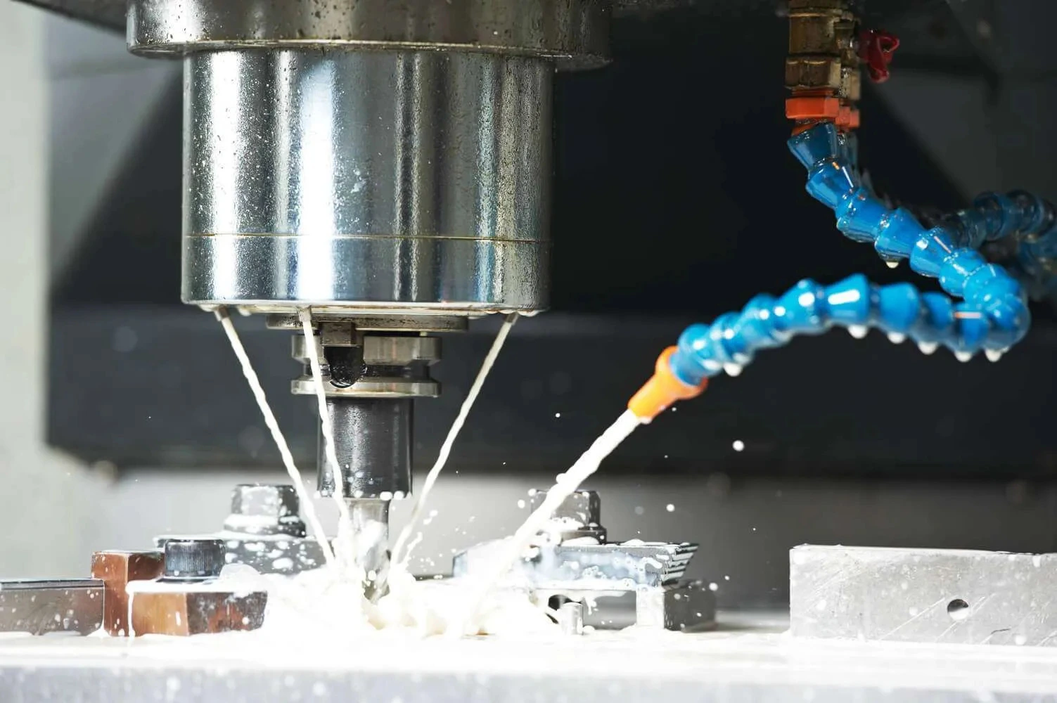

Standard vs. Custom Diamond Grinding Wheels: When Does Custom Tooling Make Engineering Sense?

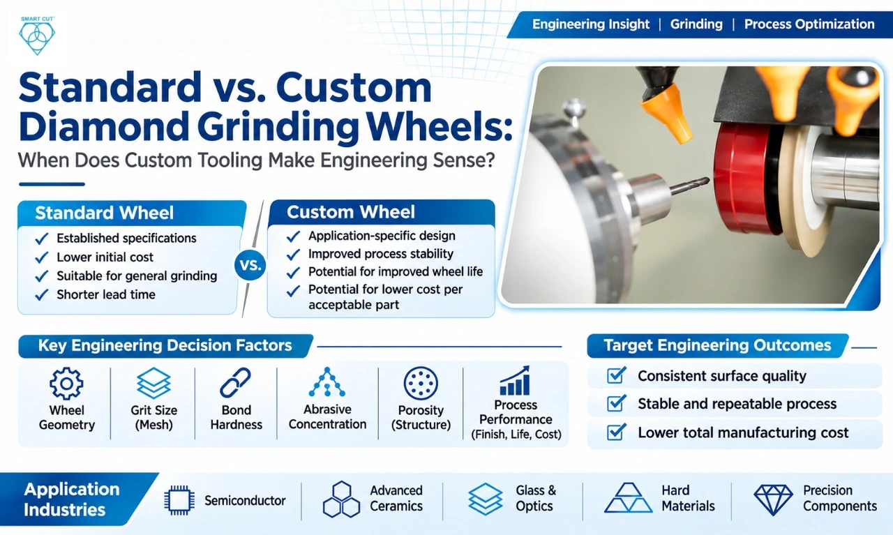
Table of Contents
Toggle
American Based Manufacturer

Established in 1990


Custom manufacturing


Selecting a diamond grinding wheel is not simply a matter of matching abrasive grit to workpiece hardness. Wheel specification directly influences material removal rate, surface integrity, dimensional accuracy, dressing frequency, cycle time, tool consumption and the cost of producing an acceptable component.
For many grinding applications, a standard diamond grinding wheel provides adequate performance. However, problems arise when the available specification cannot maintain the required process window. Excessive dressing, inconsistent surface finish, thermal damage, edge chipping and short wheel life can indicate a mismatch between the wheel specification and the actual grinding conditions.
Custom tooling may solve these problems, but a higher purchase price does not automatically make a custom wheel a better engineering decision.
The correct approach is to determine whether an available standard wheel can meet the process requirements consistently or whether a custom specification can deliver a measurable improvement in manufacturing performance and cost per acceptable part.
This article explains how engineers can make that decision using process data, wheel characteristics, machine capability, controlled qualification trials and total manufacturing cost.
Why Engineers Consider Standard and Custom Diamond Grinding Wheels
Standard diamond grinding wheels are manufactured around established dimensions, abrasive specifications and bond systems. They are generally suitable when the application falls within the operating range of an available wheel configuration.
Custom diamond grinding wheels become relevant when the process requires a combination of characteristics that an available standard specification cannot provide.
The decision commonly arises under the following conditions:
|
Engineering condition |
Potential process limitation |
What may need investigation |
|---|---|---|
|
Excessive dressing frequency |
Production interruptions and additional wheel consumption |
Bond retention, abrasive exposure and wheel structure |
|
High grinding forces |
Increased spindle load and possible thermal damage |
Abrasive concentration, bond characteristics and contact conditions |
|
Unstable surface finish |
Variation between components or production batches |
Grit distribution, wheel runout and dressing consistency |
|
Edge chipping |
Reduced component yield |
Grit size, wheel condition, feed rate and workpiece support |
|
Short wheel life |
Frequent replacement and higher tooling cost |
Bond suitability, concentration and grinding parameters |
|
Restricted machine clearance |
Standard dimensions cannot fit the operation |
Custom diameter, thickness, bore or profile |
|
Complex component geometry |
Standard wheel profile cannot maintain the required contact |
Custom profile and working-face geometry |
These symptoms do not automatically justify custom tooling. A process problem may originate from machine condition, spindle runout, coolant delivery, workholding, dressing technique or unsuitable operating parameters.
Engineers should identify the actual cause before changing the wheel specification.
Establish a Baseline Before Changing the Wheel
A reliable comparison requires a documented baseline. Without this information, an apparent improvement after introducing a custom wheel may result from an unrelated process adjustment.
Record the following information before requesting a new specification or conducting a qualification trial.
|
Parameter |
Information to record |
Engineering purpose |
|---|---|---|
|
Workpiece material |
Grade, composition and hardness |
Establishes material response |
|
Component geometry |
Dimensions, profile and contact area |
Defines grinding engagement |
|
Current wheel |
Diameter, thickness, bore, grit and bond |
Establishes the reference specification |
|
Abrasive concentration |
Published or supplier-confirmed value |
Helps compare abrasive content |
|
Wheel speed |
RPM and peripheral speed |
Establishes operating conditions |
|
Feed rate |
Linear feed or feed per revolution |
Defines material removal conditions |
|
Depth of cut |
Radial or axial engagement |
Influences grinding force and heat generation |
|
Type, concentration, flow and delivery position |
Helps assess thermal and debris removal conditions |
|
|
Dressing |
Tool type, frequency and dressing parameters |
Establishes wheel conditioning requirements |
|
Surface finish |
Measured Ra, Rz or application-specific criteria |
Defines surface quality |
|
Dimensional accuracy |
Size, flatness, parallelism or profile |
Establishes acceptance limits |
|
Wheel consumption |
Initial and final wheel dimensions |
Supports wear evaluation |
|
Machine condition |
Spindle runout, power, rigidity and speed range |
Identifies machine-related limitations |
|
Production performance |
Cycle time, scrap and accepted quantity |
Supports cost comparison |
The baseline should include actual measurements rather than operator impressions wherever possible.
For example, “the wheel is wearing quickly” is not a sufficient engineering observation. Record wheel dimensions before and after a defined production quantity, the number of dressing operations and the number of acceptable components produced.
Compare Cost Per Acceptable Part, Not Purchase Price
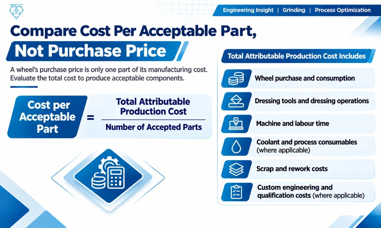
The purchase price of a diamond grinding wheel represents only one part of its manufacturing cost.
A less expensive wheel may require more frequent dressing, longer grinding cycles and additional operator intervention. A custom wheel may cost more initially but reduce the total cost of producing acceptable components.
A useful comparison is:
Cost per acceptable part = Total attributable production cost ÷ Number of accepted parts
Total attributable production cost can include:
- Wheel purchase and consumption.
- Dressing tools and dressing operations.
- Machine and labour time.
- Coolant and process consumables, where material.
- Scrap and rework costs.
- Custom engineering and qualification costs, where applicable.
Illustrative supplier comparison
The following example uses hypothetical figures to demonstrate the calculation. It is not a UKAM customer result or a published production trial.
Assume two wheel options are evaluated for the same component and production requirement.
|
Parameter |
Supplier A: Standard wheel |
Supplier B: Custom wheel |
|---|---|---|
|
Wheel purchase price |
$180 |
$420 |
|
$420 |
1 |
1 |
|
Components processed |
1,200 |
3,600 |
|
Dressing interval |
100 parts |
300 parts |
|
Intermediate dressing events |
11 |
11 |
|
Cost per dressing event |
$12 |
$12 |
|
Grinding cycle time |
2.4 min |
2.1 min |
|
Machine and labour rate |
$90/hour |
$90/hour |
|
Scrap rate |
4.0% |
1.5% |
|
Accepted components |
1,152 |
3,546 |
For this example, one wheel is charged to each production lot. Both wheels complete their respective lots with 11 intermediate dressing events. No additional dressing is charged after the final component. This is a simplified comparison and assumes the wheel remains usable throughout the stated lot.
Supplier A calculation
Wheel cost: $180
Dressing cost: 11 × $12 = $132
Machine and labour cost:
1,200 × 2.4 ÷ 60 × $90 = $4,320
Scrap material cost, assuming $1.50 per rejected component:
48 × $1.50 = $72
Total cost:
$180 + $132 + $4,320 + $72 = $4,704
Cost per acceptable part:
$4,704 ÷ 1,152 = $4.08
Supplier B calculation
Wheel cost: $420
Dressing cost: 11 × $12 = $132
Machine and labour cost:
3,600 × 2.1 ÷ 60 × $90 = $11,340
Scrap material cost:
54 × $1.50 = $81
Total cost:
$420 + $132 + $11,340 + $81 = $11,973
Cost per acceptable part:
$11,973 ÷ 3,546 = $3.38
Under these illustrative assumptions, the custom wheel produces an approximately 17.3% lower cost per acceptable part.
The result does not mean custom wheels are always more economical. It demonstrates why engineers should compare complete production costs rather than wheel purchase prices.
A production model should also account for wheel replacement frequency, actual wheel consumption, rework, inspection, setup and downtime where these costs materially affect the result.
Include custom engineering and qualification costs
A custom wheel may require design work, sample production, machine trials and process validation.
These costs should be included in the investment decision.
Break-even production quantity = Custom development and qualification cost ÷ Expected savings per acceptable part
If the custom specification saves $0.70 per accepted component and development and qualification cost $3,500, the approximate break-even quantity is:
$3,500 ÷ $0.70 = 5,000 acceptable components
This simplified calculation assumes the estimated savings remain consistent over the production volume. In a real evaluation, engineers should also account for production variation, wheel replacement frequency, validation requirements and the expected useful life of the custom specification.
Which Wheel Characteristics Should Engineers Specify?
A custom wheel should not be defined only by diameter, grit size and bond type. The specification must reflect the grinding mechanism, material response, machine capability and required surface condition.
Diamond grit size
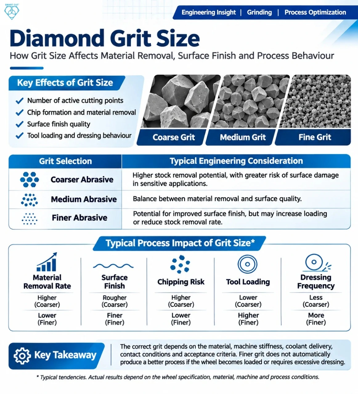
Grit size affects the number of active cutting points, chip formation, surface finish and material removal behaviour.
|
Grit selection |
Typical engineering consideration |
|---|---|
|
Coarser abrasive |
Higher stock removal potential, with greater risk of surface damage in sensitive applications |
|
Medium abrasive |
Balance between material removal and surface quality |
|
Finer abrasive |
Potential for improved surface finish, but may increase loading or reduce stock removal rate |
The correct grit depends on the material, machine stiffness, coolant delivery, contact conditions and acceptance criteria. Finer grit does not automatically produce a better process if the wheel becomes loaded or requires excessive dressing.
Bond type and bond hardness
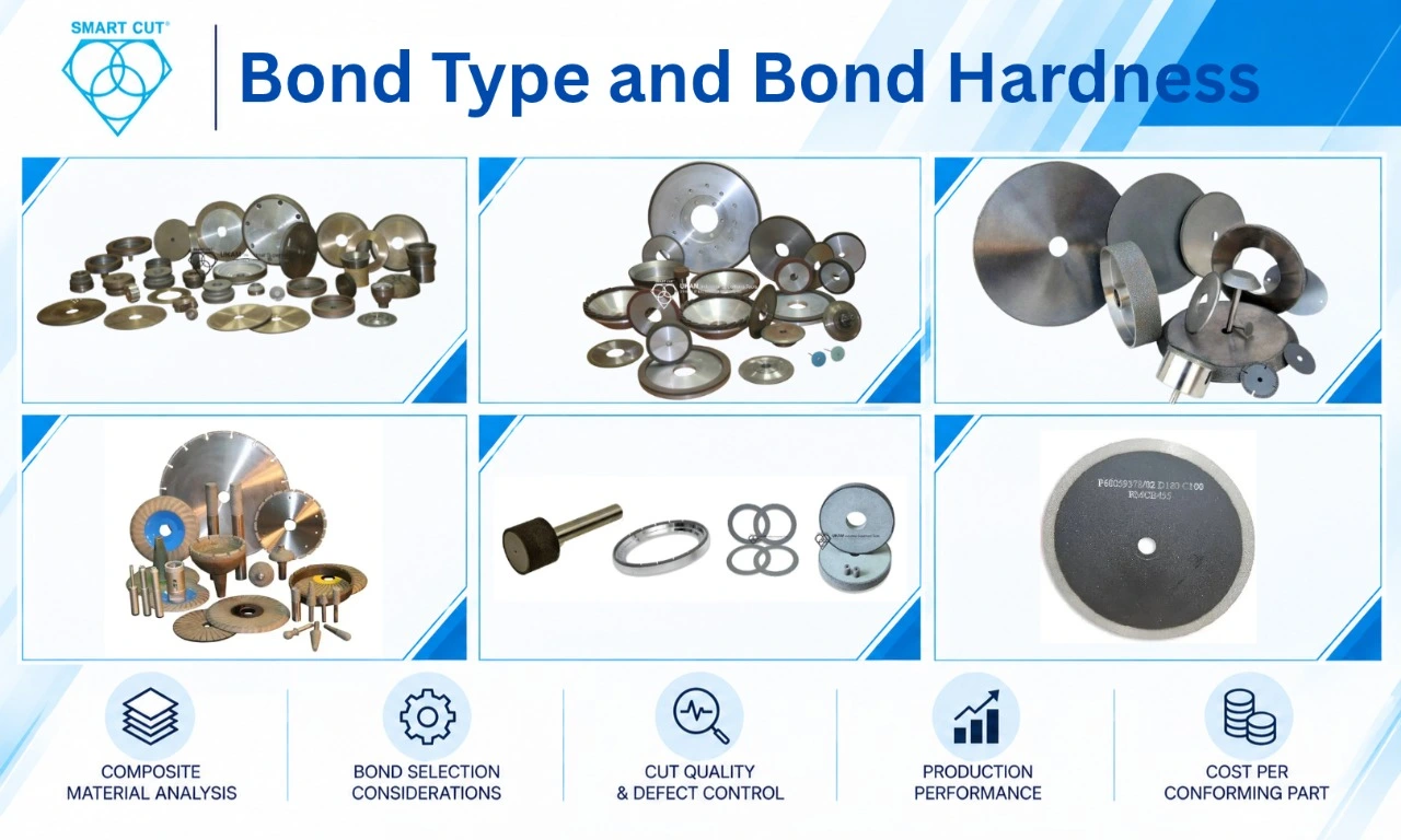
Bond selection determines how diamond abrasive is retained and how the wheel responds during grinding and dressing.
|
Bond system |
Engineering characteristics |
Application considerations |
|---|---|---|
|
Often selected for fine finishing and controlled surface quality |
Formulation, thermal limits and wheel stiffness require evaluation |
|
|
Provides strong abrasive retention and wear resistance |
Dressing and conditioning requirements must be evaluated |
|
|
Can provide a porous structure and controlled wheel behaviour |
Bond strength, structure and dressing response require consideration |
|
|
Holds abrasive particles at the wheel surface through a plated retaining layer |
Suitable for specific profiles and applications where the construction is appropriate |
|
|
Uses a metallurgical attachment between abrasive and substrate |
Useful where abrasive exposure and retention characteristics are required |
|
|
Combines characteristics of different bond approaches |
Performance depends on the specific formulation and construction |
Bond hardness and wheel structure are related but are not interchangeable.
Bond hardness describes the resistance of the bond system to releasing abrasive particles under grinding conditions. Wheel structure describes the spacing between abrasive grains and the available void volume.
A wheel with excessive abrasive retention may become dull without releasing worn grains. This can increase grinding forces and heat generation. A wheel with insufficient retention may lose abrasive prematurely and wear rapidly.
The objective is not simply to select a soft or hard bond. It is to establish a suitable relationship between abrasive retention, grain exposure, chip clearance and dressing response.
Wheel structure and porosity
Wheel structure influences the available space between abrasive grains.
More open structures can provide additional clearance for chips and coolant, which may be beneficial in applications prone to loading. However, a more open structure can also affect wheel strength and the number of active cutting points.
Engineers should evaluate:
- Chip size and material loading behaviour.
- Contact area between wheel and workpiece.
- Coolant access to the grinding zone.
- Grinding force and temperature.
- Required wheel stiffness and profile retention.
- Dressing response.
Abrasive concentration
Diamond concentration affects the amount of abrasive present in the active layer.
A higher concentration may increase the number of available cutting points, but it does not guarantee longer wheel life or better surface finish. Grain size, bond formulation, structure and operating conditions also influence performance.
Engineers should request the supplier’s concentration definition and specification rather than comparing concentration figures without confirming that the same convention is being used.
Machine Capability and Operating Conditions
A wheel specification cannot compensate for inadequate machine capability.
Before ordering a custom diamond grinding wheel, engineers should verify that the machine can support the proposed wheel geometry and operating conditions.
|
Machine parameter |
Why it matters |
|---|---|
|
Spindle speed range |
Determines whether the required operating speed is achievable |
|
Maximum permissible wheel speed |
Defines the wheel's safe operating limit |
|
Spindle runout |
Can affect contact consistency, finish and dimensional accuracy |
|
Machine rigidity |
Influences deflection, vibration and grinding stability |
|
Available spindle power |
Limits the load that can be applied during grinding |
|
Mounting interface |
Determines wheel fit and alignment |
|
Coolant delivery |
Affects heat removal, chip evacuation and loading |
|
Workholding |
Influences component stability and edge integrity |
Wheel peripheral speed can be calculated using:
vₛ = π × D × n ÷ 60,000
Where:
- vₛ = wheel peripheral speed in metres per second.
- D = wheel diameter in millimetres.
- n = rotational speed in revolutions per minute.
For example, a 200 mm diameter wheel operating at 3,000 RPM has a calculated peripheral speed of approximately 31.4 m/s.
This calculation does not establish a safe operating speed. The maximum permissible speed marked or specified for the complete wheel assembly must not be exceeded. The wheel, core, mounting system and machine must all be suitable for the intended operation.
A custom wheel should be specified with the machine interface, operating speed and applicable safety requirements confirmed before manufacture.
A Practical Method for Deciding Between Standard and Custom Wheels
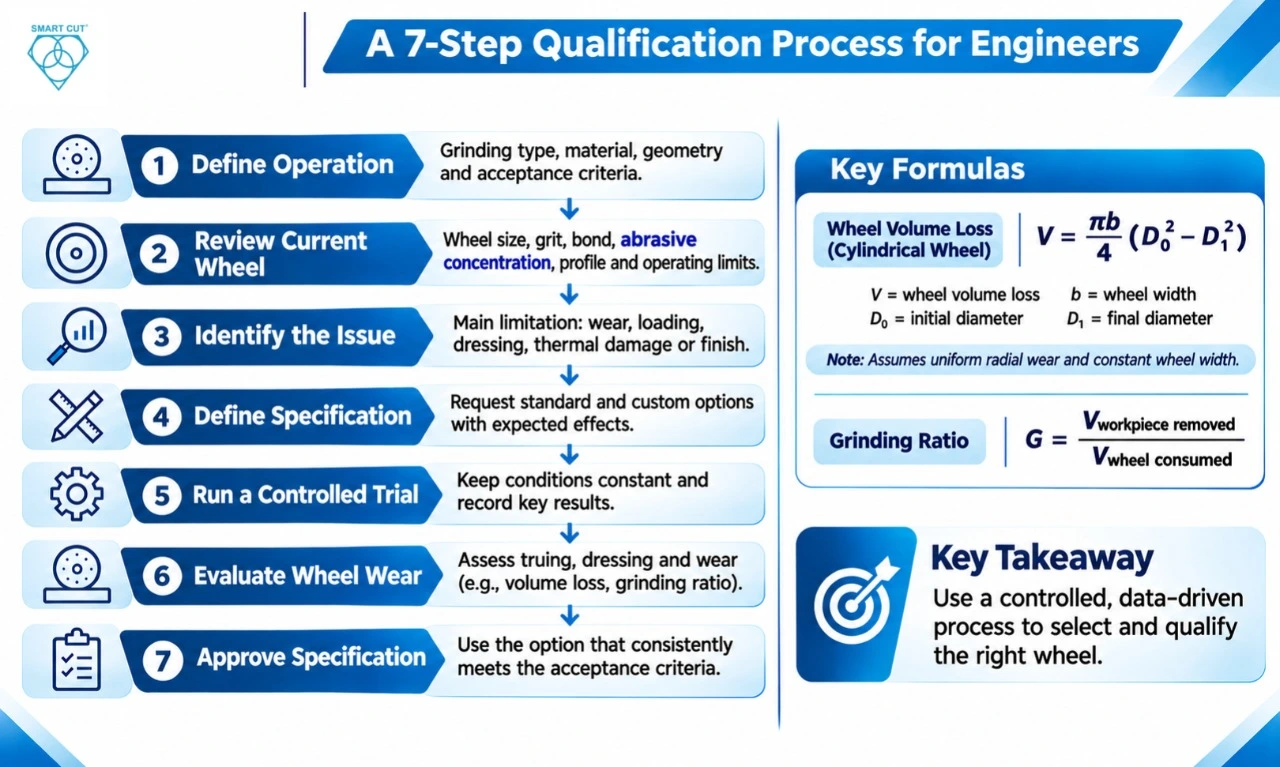
Use a controlled qualification process instead of selecting custom tooling based only on an assumed performance advantage.
Phase 1: Define the grinding operation
Identify whether the process involves surface grinding, cylindrical grinding, internal grinding, tool grinding, creep-feed grinding or profile grinding.
Document the workpiece material, component geometry, grinding allowance and acceptance criteria.
Phase 2: Review the existing wheel
Record the complete wheel specification, including:
- Diameter, thickness and bore.
- Abrasive type and grit size.
- Bond system and concentration.
- Wheel profile and working-face geometry.
- Maximum operating speed.
- Manufacturer's dressing recommendations.
Check whether the existing wheel is being operated within its rated limits.
Phase 3: Investigate the process limitation
Identify whether the main problem is wheel wear, loading, dressing frequency, thermal damage, poor surface finish, dimensional variation or restricted geometry.
Do not assume that changing the bond will correct a problem caused by inadequate coolant delivery or machine instability.
Phase 4: Define the proposed specification
Request a standard alternative and a custom alternative where both are technically plausible.
For each option, ask the supplier to explain the expected effect of the proposed grit, bond, concentration, structure and geometry.
The supplier should also identify any operating or dressing requirements that differ from the current process.
Phase 5: Conduct a controlled trial
Keep the machine, workpiece material, coolant and inspection method consistent.
Change only the variables required by the trial plan. If several process parameters change simultaneously, it becomes difficult to determine which change caused the result.
Record:
- Grinding forces or spindle load, where available.
- Cycle time.
- Dressing frequency.
- Wheel dimensional wear.
- Surface finish.
- Dimensional accuracy.
- Defect rate.
- Accepted components per wheel.
Phase 6: Evaluate truing, dressing and wheel wear
Truing, dressing and conditioning are related wheel-maintenance operations, but they should not be treated as identical.
- Truing restores the required wheel geometry, concentricity or running accuracy.
- Dressing renews the wheel's cutting action by exposing abrasive grains and removing loading or dull bond material, depending on wheel construction.
- Conditioning is a broader term used for preparing the wheel surface for the required grinding behaviour. The exact operation depends on the wheel and process.
Some operations can combine truing and dressing. The appropriate method depends on the bond system and wheel design.
Wheel wear should not be evaluated from diameter reduction alone in every application.
For a simple cylindrical wheel with approximately uniform radial wear, estimated wheel volume loss can be calculated using:
Vwheel = πb/4 × (D₀² − D₁²)
Where:
- Vwheel = estimated wheel material volume loss.
- b = wheel width.
- D₀ = initial wheel diameter.
- D₁ = final wheel diameter.
This approximation assumes uniform radial wear and a consistent wheel width. It may not accurately represent profile wear, local wear, corner breakdown or changes in working-face geometry.
For profile wheels, more detailed dimensional measurement or 3D inspection may be necessary.
The grinding ratio can be expressed as:
G = Vworkpiece removed ÷ Vwheel consumed
A higher grinding ratio indicates less wheel volume consumed for a given volume of workpiece material removed. However, grinding ratio should not be used alone. Surface integrity, dimensional accuracy, cycle time and dressing requirements remain important.
Phase 7: Approve the production specification
A wheel should only be approved when it consistently meets the defined acceptance criteria.
The final specification should include wheel dimensions, abrasive characteristics, bond, concentration, operating limits, dressing method and inspection requirements.
The approved specification should also be linked to the machine and application for which it was qualified.
Material-Specific Considerations
The same wheel specification should not be assumed to perform equally across different hard and brittle materials.
Silicon carbide
Silicon carbide is hard and brittle. Grinding can produce subsurface microcracking and edge chipping, particularly when abrasive engagement and grinding forces are poorly controlled.
Engineers should evaluate grit size, bond behaviour, coolant delivery, feed rate and component support. A custom specification may be justified where the standard wheel cannot maintain the required balance between stock removal and edge integrity.
Alumina ceramics
Alumina grinding can produce grain pullout and surface pitting. The result depends on grain structure, material grade, wheel condition and grinding parameters.
The wheel must provide sufficient cutting action without creating excessive local stress. Surface inspection should include the defect types relevant to the component’s function.
Silicon nitride
Silicon nitride has high hardness and fracture resistance, but grinding can still produce localized subsurface cracking and edge fracture.
Wheel selection should account for the material grade, component geometry, stock removal requirement and thermal conditions. A controlled trial should verify both surface quality and dimensional stability.
Tungsten carbide
Tungsten carbide is a composite material containing hard carbide grains and a metallic binder phase.
Grinding can cause binder-related damage, carbide grain pullout, edge chipping and excessive wheel wear. The appropriate abrasive and bond combination depends on carbide grade, binder content and the grinding operation.
Sapphire
Sapphire is hard and brittle. Edge chipping and subsurface fracture can affect component yield, especially where edge quality or optical performance is critical.
Engineers should assess abrasive size, contact conditions, support, coolant delivery and the inspection method used to detect damage.
Fused silica
Fused silica can develop surface microcracking and subsurface damage during grinding.
The required surface condition should determine whether a standard grinding wheel is sufficient or whether a more specific wheel and finishing sequence are required.
Gallium arsenide
Gallium arsenide is a semiconductor material that requires careful control of wafer edge condition and surface damage.
Edge chipping, cracking and localized wafer damage should be evaluated during qualification. Process conditions and downstream inspection requirements must be considered together.
Polycrystalline diamond
PCD grinding involves a composite structure of diamond grains and a metallic binder phase.
Potential problems include diamond grain pullout, binder-related degradation and edge microfracture. Wheel selection should reflect the PCD grade, binder composition, required profile and finishing objective.
Illustrative Qualification Example: Silicon Carbide Grinding
The following scenario is hypothetical and is provided to demonstrate the engineering decision process. It is not an actual UKAM customer case study or a verified production result.
A manufacturer is grinding silicon carbide components using a standard diamond wheel. The process meets dimensional requirements but produces inconsistent edge quality and requires frequent dressing.
The engineering team identifies three areas for investigation:
- The existing wheel's abrasive and bond characteristics.
- The relationship between grinding engagement and edge chipping.
- The effect of dressing frequency on production consistency.
Rather than immediately ordering a custom wheel, the team records the existing process parameters and establishes a repeatable inspection method.
A custom wheel is then proposed with a revised abrasive specification and bond characteristics intended to improve cutting behaviour and dressing stability.
The qualification trial compares the standard and custom wheels under controlled conditions.
|
Evaluation measure |
Standard wheel |
Custom wheel |
|---|---|---|
|
Grinding cycle time |
Record baseline |
Measure during trial |
|
Dressing frequency |
Record baseline |
Compare with baseline |
|
Wheel wear |
Measure dimensional loss |
Measure dimensional loss |
|
Edge chipping |
Inspect and classify |
Inspect and classify |
|
Surface condition |
Measure against acceptance criteria |
Measure against acceptance criteria |
|
Accepted components |
Count |
Count |
|
Cost per acceptable part |
Calculate |
Calculate |
No numerical improvement should be claimed until the trial produces verified measurements.
The custom wheel should be approved only if it demonstrates repeatable improvement in the required process outcomes without introducing unacceptable changes to dimensional accuracy, surface integrity or operating stability.
How to Specify a Custom Diamond Grinding Wheel
An engineering specification should connect the required wheel construction to the machine, workpiece and grinding operation.
The following is an illustrative RFQ specification format, not an actual UKAM product specification.
|
Specification field |
Example information to provide |
|---|---|
|
Application |
Precision surface grinding |
|
Workpiece |
Silicon carbide ceramic |
|
Wheel shape |
1A1, subject to drawing and machine compatibility |
|
Outside diameter |
200 mm |
|
Thickness |
10 mm |
|
Bore |
31.75 mm |
|
Abrasive |
|
|
Grit |
To be recommended based on stock removal and finish requirements |
|
Bond |
To be evaluated through supplier recommendation |
|
Concentration |
To be specified by supplier |
|
Machine |
Manufacturer and model to be supplied |
|
Operating speed |
Actual RPM and permitted wheel speed to be confirmed |
|
Coolant |
Type and delivery conditions to be documented |
|
Required finish |
Defined Ra or other relevant acceptance criterion |
|
Dimensional tolerance |
Defined from component drawing |
|
Qualification objective |
Reduce dressing interruptions while maintaining surface integrity |
The example shows why an RFQ should not force a supplier to guess the bond, grit and concentration without understanding the application.
A technically useful RFQ provides the material, machine, operating conditions and performance requirements. The supplier can then recommend a wheel construction for qualification.
How to Evaluate a Diamond Grinding Wheel Supplier
A technically capable supplier should be able to explain the relationship between the proposed wheel specification and the application.
|
Measurement |
Slurry process |
Diamond wire process |
|---|---|---|
|
Example feed rate |
0.42 mm/min |
1.0 mm/min |
|
Cutting time for 156 × 156 mm silicon |
6.8 hours |
3.6 hours |
|
Reported capacity for 156 × 156 mm wafers |
6,500 wafers/day |
13,800 wafers/day |
|
Cutting time for 125 × 125 mm silicon |
5.6 hours |
2.6 hours |
|
Reported capacity for 125 × 125 mm wafers |
7,800 wafers/day |
16,100 wafers/day |
|
Reported heat induction |
40–60°C |
Below 20°C |
Be cautious of recommendations based only on material hardness or a general statement that a particular bond is suitable for all ceramic grinding applications.
A wheel specification should be supported by an explanation of its expected behaviour under the actual grinding conditions.
Standard and Custom Diamond Grinding Wheel Options from SMART CUT
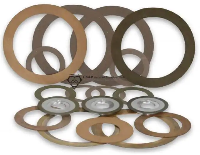
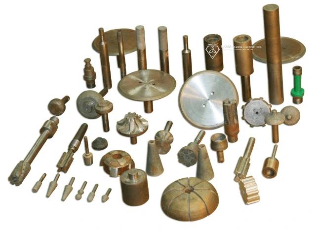
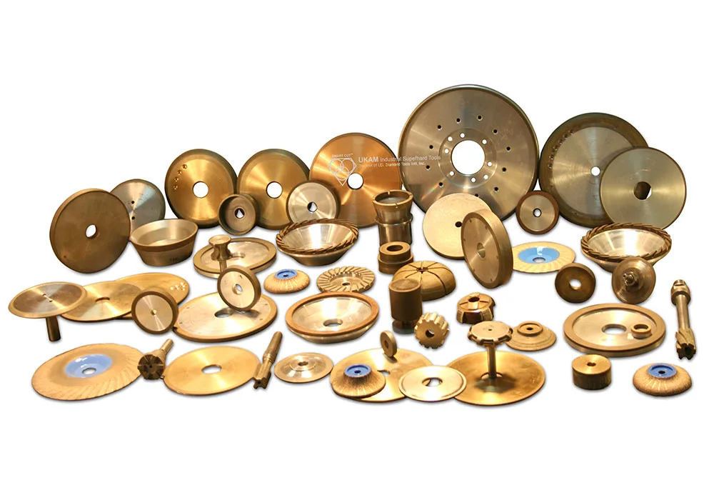
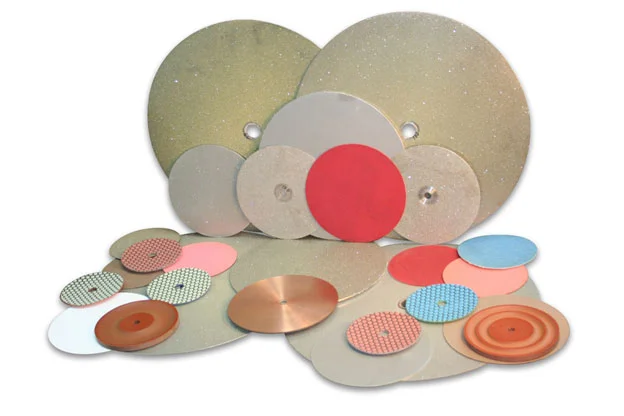
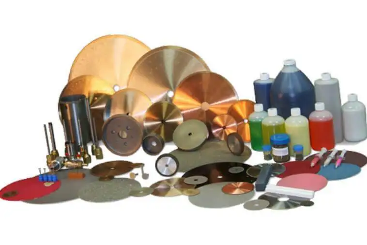
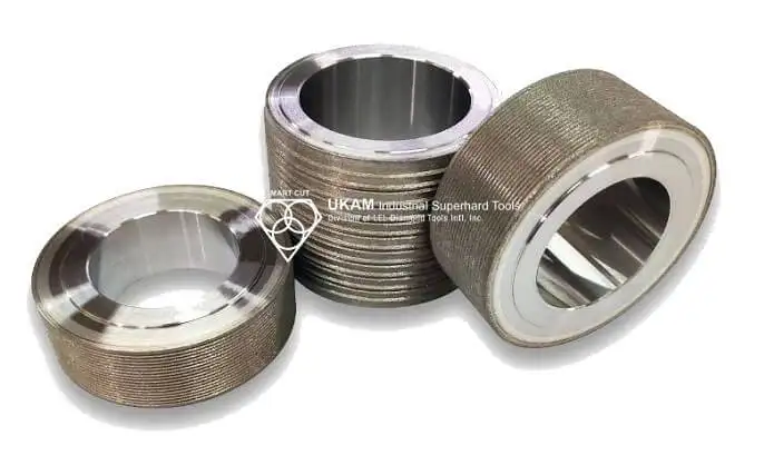
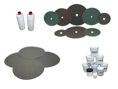
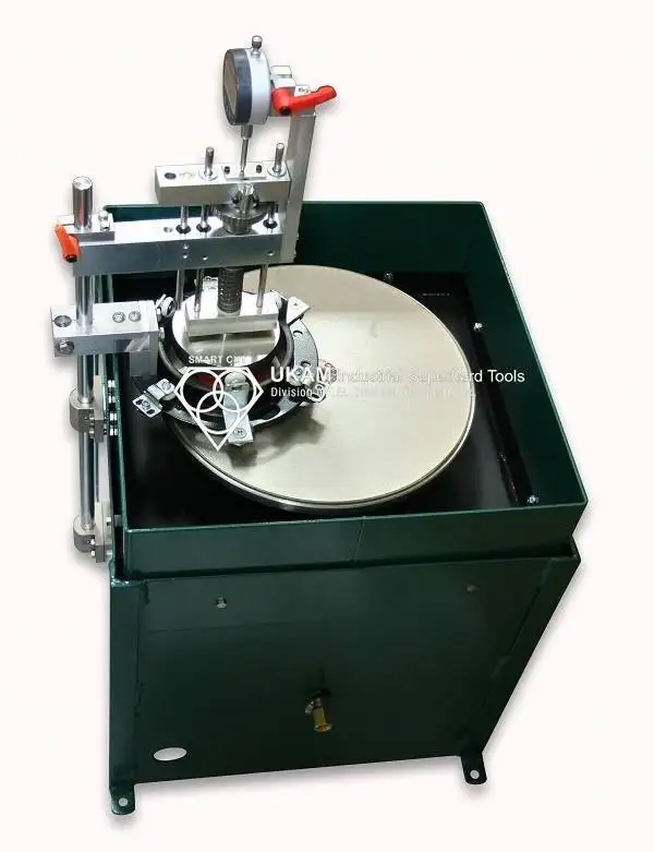
SMART CUT diamond and CBN wheel configurations from UKAM Industrial Superhard Tools can be evaluated according to the dimensions, abrasive characteristics, bond and profile requirements of the application.
UKAM lists a range of wheel configurations and bond options, including resin, sintered metal, hybrid, nickel-plated, brazed and vitrified constructions. Specific availability and specifications depend on the wheel series and application.
The SMART CUT 1A1 product range, for example, lists several bond options and wheel sizes from 1 inch to 27 inches. These specifications should not be assumed to apply to every SMART CUT wheel family.
Relevant product information:
The appropriate product specification should be confirmed with UKAM against the required dimensions, abrasive characteristics, bond, machine interface and operating conditions.
Engineers should not select a wheel solely because its nominal grit size or bond description matches an existing specification. The complete wheel configuration and application conditions determine whether it is suitable.
Engineering RFQ Checklist for Standard or Custom Diamond Grinding Wheels
A technical RFQ should provide enough information for the supplier to evaluate the application rather than simply quote a wheel by diameter and grit size.
Workpiece information
- Material name and grade.
- Hardness or relevant material properties.
- Component drawing or geometry.
- Grinding allowance.
- Required surface finish and dimensional tolerances.
Machine information
- Machine manufacturer and model.
- Spindle speed range.
- Available power and operating limits.
- Wheel mounting arrangement.
- Maximum permitted wheel dimensions.
- Spindle runout and relevant machine condition information.
Current wheel information
- Wheel diameter, thickness and bore.
- Abrasive type and grit size.
- Bond and concentration.
- Wheel profile.
- Current truing and dressing methods and frequency.
Process information
- Grinding operation.
- Workpiece speed and feed rate, where applicable.
- Depth of cut.
- Coolant type and delivery method.
- Current cycle time.
- Wheel wear and replacement frequency.
Performance requirements
- Required material removal rate.
- Surface finish target.
- Dimensional acceptance criteria.
- Permitted edge chipping or defect limits.
- Target production quantity.
- Required cost per acceptable part, if established.
Providing this information allows the supplier to assess whether an existing standard wheel is suitable or whether a custom specification deserves qualification.
Frequently Asked Questions
A custom wheel should be considered when an available standard configuration cannot meet the required dimensions, profile, surface condition, production rate or process stability. The decision should be supported by documented process limitations and a measurable qualification objective.
Custom wheels may involve additional specification or development work, but the total cost depends on the design and manufacturing requirements. A higher purchase price may be offset by longer useful life, reduced dressing, improved cycle time or lower scrap. The correct comparison is cost per acceptable part.
No. Concentration affects the amount of abrasive in the working layer, but wheel life also depends on grit size, bond formulation, structure, grinding conditions and dressing. A higher concentration does not automatically improve cutting efficiency or reduce total production cost.
There is no universally best bond for all ceramics. Alumina, silicon carbide, silicon nitride and other advanced ceramics have different grinding characteristics. Bond selection should account for abrasive retention, wheel wear, dressing response, coolant conditions and required surface integrity.
It may help when the existing wheel specification contributes to excessive grinding forces or unsuitable abrasive engagement. However, edge chipping can also result from workholding, component geometry, feed rate, machine vibration or inadequate support. The actual cause should be established before changing the wheel.
Wheel life should be measured using defined production and inspection criteria. Record wheel dimensional wear, dressing frequency, components processed, surface quality, dimensional accuracy and accepted component quantity. Diameter reduction alone may not represent the true wear condition of a profiled wheel.
Provide the workpiece material and grade, component drawing, grinding operation, machine details, wheel dimensions, spindle speed, coolant conditions, required surface finish, dimensional tolerances and current process limitations. This information helps the supplier evaluate the complete application.
Yes. A standard wheel can be suitable when its dimensions, abrasive characteristics, bond and operating limits match the application. Custom tooling is not inherently more precise. Both standard and custom wheels require appropriate machine setup, dressing and process qualification.
Engineering Principles for Making the Decision
The decision between a standard and custom diamond grinding wheel should be based on measurable process requirements rather than purchase price or assumptions about wheel performance.
The following principles provide a practical basis for selection:
- Establish the actual grinding limitation before changing the wheel.
- Record baseline machine, wheel and workpiece data.
- Evaluate grit, bond, concentration and structure as an interacting specification.
- Consider dressing response and coolant access alongside abrasive retention.
- Verify spindle capability, runout, mounting and permitted operating speed.
- Compare total cost per acceptable part rather than wheel price alone.
- Include custom engineering and qualification costs in the investment calculation.
- Conduct controlled trials using consistent inspection criteria.
- Approve a custom specification only after repeatable performance has been demonstrated.
Need a Diamond Grinding Wheel Specification for Your Application?
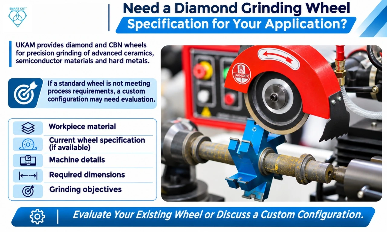
UKAM Industrial Superhard Tools manufactures and supplies diamond and CBN wheel configurations for precision grinding applications involving advanced ceramics, semiconductor materials, hard metals and other difficult-to-machine materials.
If a standard wheel is not meeting your process requirements, provide the workpiece material, current wheel specification, machine details, required dimensions and grinding objectives.
This information can help determine whether an existing SMART CUT configuration is suitable or whether a custom diamond grinding wheel should be evaluated.
The objective is not simply to purchase a different wheel. It is to establish a wheel specification that meets the required process conditions and delivers an acceptable cost per part.
Trusted by Tens of Thousands of Manufacturers, Laboratories,
Research Institutions Worldwide Since 1990
American Based Manufacturer
Established in 1990
