


PCD End Mill vs. Face Mill: What Every Engineer Should Know Before Choosing a Milling Tool
Table of Contents
ToggleTrusted by Tens of Thousands of Manufacturers, Laboratories Research Institutions Worldwide Since 1990

American Based Manufacturer

Established in 1990


Custom manufacturing


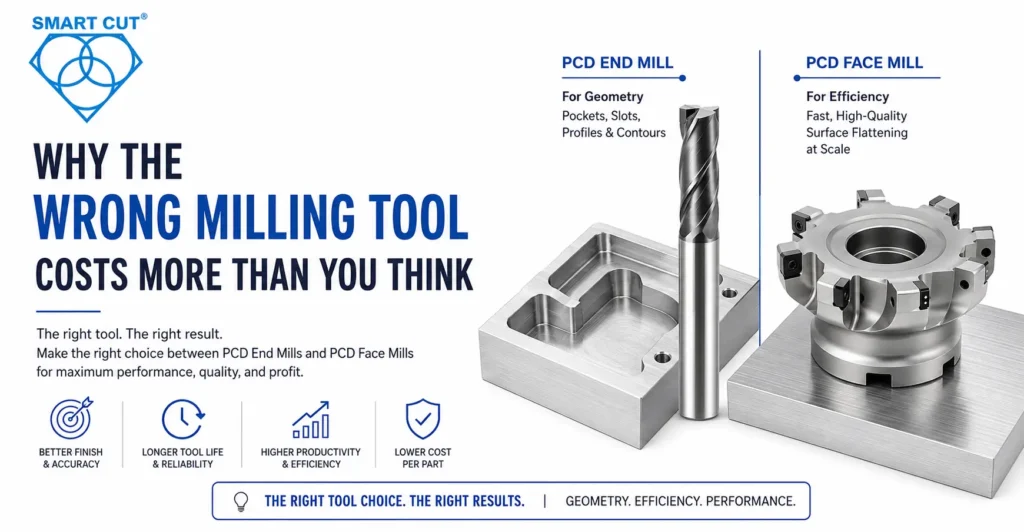
Why the Wrong Milling Tool Costs More Than You Think
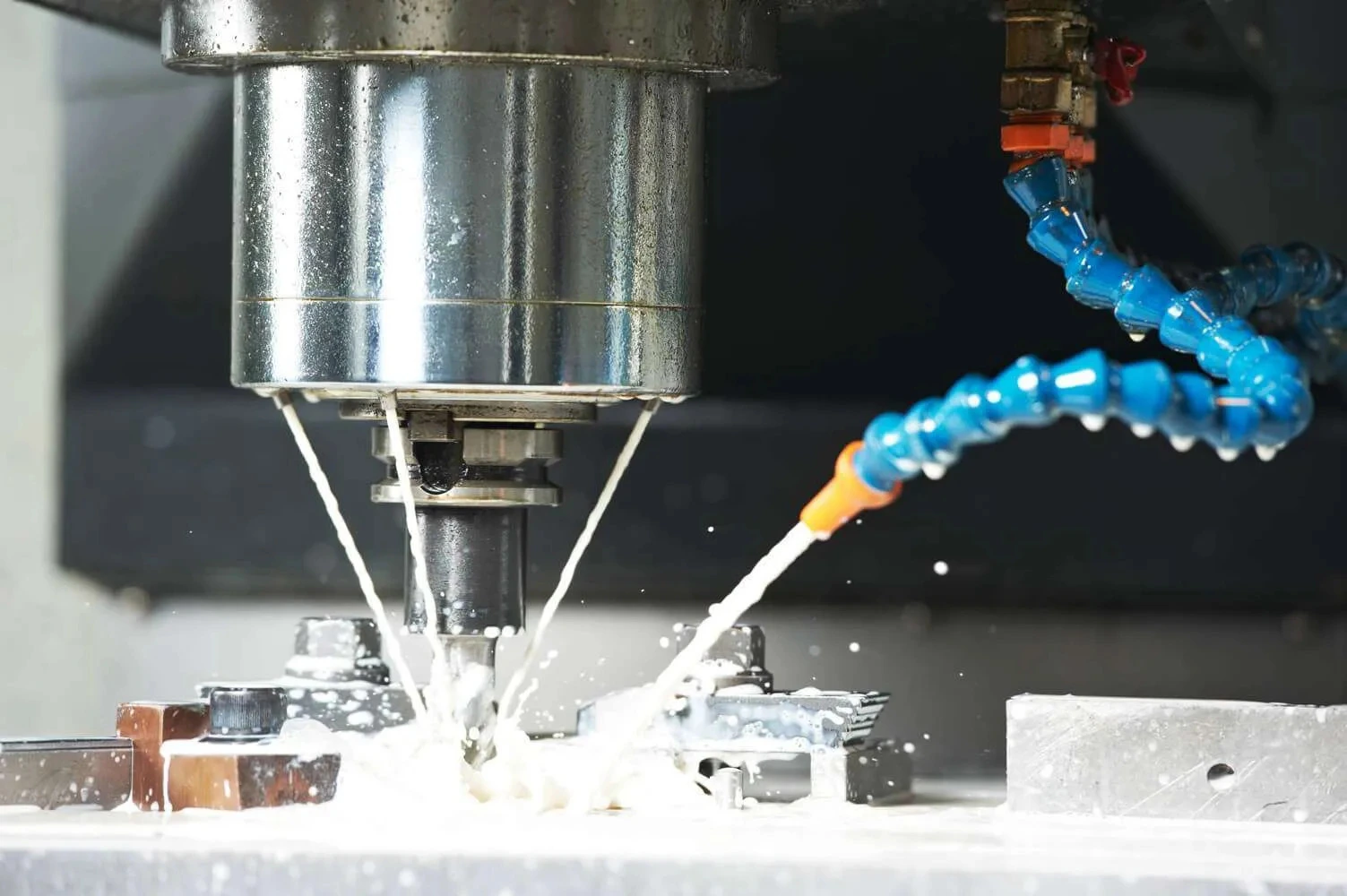
When your production line depends on consistent part geometry, surface finish, and repeatable tolerances, choosing the wrong milling tool is not a minor inconvenience. It means scrap parts, broken tooling, and unplanned downtime. For engineers and process planners working with non-ferrous metals, composites, and ultra-hard materials, the choice between a PCD end mill and a PCD face mill comes up constantly.
At UKAM Industrial Superhard Tools, we have spent over three decades working directly with manufacturers, research institutions, and production environments where this decision has real consequences. This guide breaks down the core differences — including cutting data, CAM strategy, surface finish targets, and tool life — so you can make the right call for your specific application.
Quick Reference: PCD end mills are for geometry — pockets, slots, profiles, and contours. PCD face mills are for efficiency — fast, high-quality surface flattening at production scale. These tools solve different problems and complement each other.
What Is a PCD End Mill?
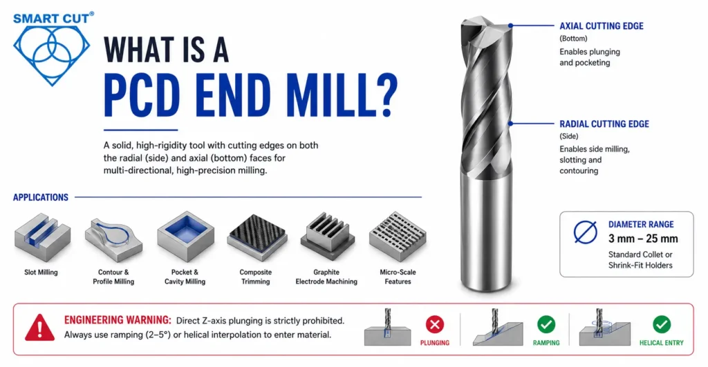
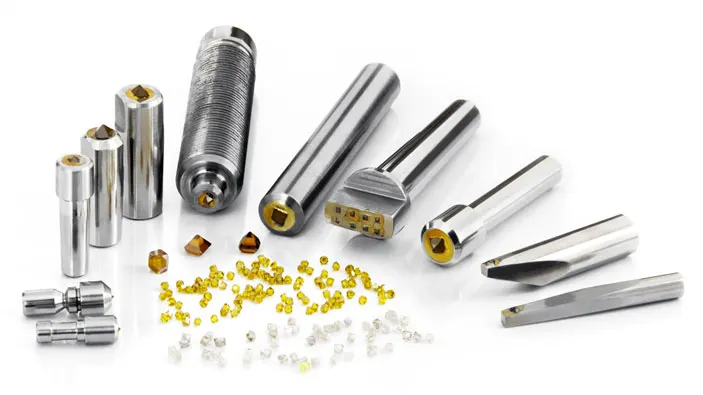
A PCD end mill is a solid or brazed-tip tool with cutting edges positioned on both the radial (side) and axial (bottom) faces. The tool is designed for multi-directional cutting — sideways, downwards, and along complex toolpaths. Most PCD end mills range from 3 mm to 25 mm in diameter and mount in standard collet or shrink-fit holders.
The monoblock construction — PCD tips brazed directly onto a solid tungsten carbide body — maximizes rigidity and resists the side-loading forces that cause deflection and dimensional error in small-diameter tools.
UKAM’s PCD and PCBN tool line includes spiral end mills engineered for high stock removal in composite trimming — including aerospace fuselage opening applications — as well as ball-nose end mills for generating accurate 3D surface profiles in composite parts.
PCD End Mill Applications
- Slot milling — cutting narrow internal channels to exact width and depth
- Contour and profile milling — shaping external part boundaries to tight tolerances
- Pocket and cavity creation — milling enclosed internal pockets in aluminum, CFRP, graphite, or ceramic-filled polymers
- Composite routing and trimming — cleanly shearing carbon fiber and glass fiber without delamination or fraying
- Graphite electrode machining — high-precision features in EDM electrodes requiring excellent edge retention
- Micro-scale features in advanced ceramics, MMC, and semiconductor substrates
Engineering Warning: Direct Z-axis plunging is strictly prohibited with PCD end mills. The diamond edge is hard but brittle under crush loading. All CNC programs must use ramping (2 to 5 degree ramp angle) or helical interpolation to enter solid material. This must be built into every CAM toolpath before spindle contact.
What Is a PCD Face Mill?
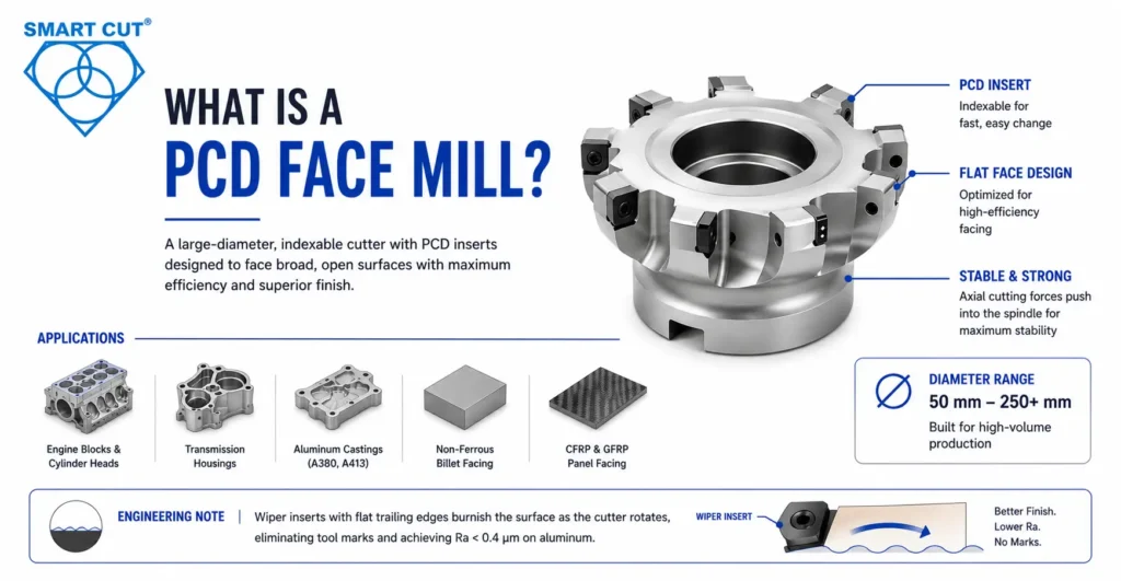
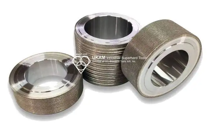
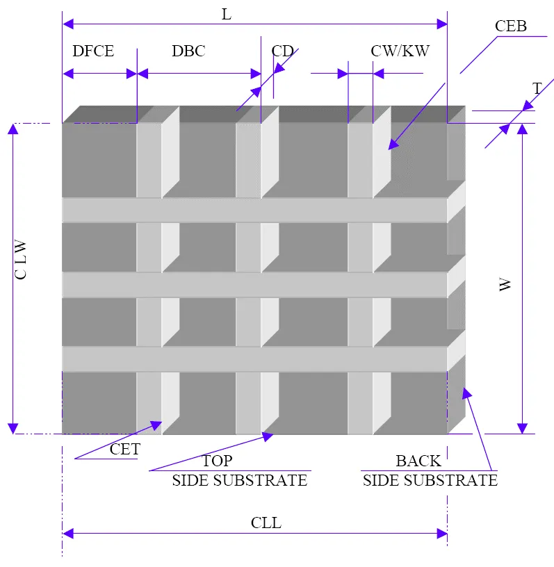
A PCD face mill is a large-diameter, indexable cutter with PCD inserts mounted on the periphery of a flat disk body. The tool moves horizontally across a workpiece, removing shallow layers of material to produce a flat, consistent surface. Diameters typically start at 50 mm and can exceed 250 mm for high-volume production applications.
Unlike a PCD end mill, a face mill has no flutes along its sides and cannot cut into the walls of a cavity. It is purpose-built for one task: facing broad, open external surfaces with maximum material removal efficiency and excellent surface finish. The axial cutting forces push directly into the spindle, creating exceptional stability even under heavy cuts.
Face mills use indexable insert systems — small PCD cartridges bolted into precisely machined pockets in the cutter body. When an insert wears, an operator swaps it in minutes without removing the cutter from the spindle. This is a critical maintenance advantage in high-volume production environments.
PCD Face Mill Applications
- Decking aluminum engine blocks and cylinder heads in automotive production
- Facing aluminum transmission housings and pump bodies
- Finishing silicon-rich aluminum castings (A380, A413) to mirror-level surface quality
- High-throughput facing of non-ferrous billet material before secondary operations
- Large CFRP and GFRP panel facing in aerospace structural manufacturing
Engineering Note: PCD face mills configured with wiper inserts — flat trailing edges on specific insert positions — burnish the machined surface as the cutter rotates, eliminating visible tool marks across the entire face. Wiper geometry is the key to achieving Ra below 0.4 microns on aluminum without post-machining polishing.
Technical Comparison Tables
Table 1: Structural and Geometric Comparison
|
Feature |
PCD End Mil |
PCD Face Mill |
|---|---|---|
|
Cutting edge location |
Radial sides + axial bottom |
Peripheral face only |
|
Typical diameter rang |
3 mm to 25 mm |
50 mm to 250 mm+ |
|
Tool construction |
Monoblock (brazed tips) |
Indexable (removable inserts) |
|
Mounting method |
Collet / shrink-fit shank |
Arbor mount |
|
Primary cutting force |
Radial (side-loading) |
Axial (into spindle) |
|
Direct Z-axis plunging |
Not permitted |
Not possible |
|
Cavity / pocket machining |
Yes |
No |
|
Large surface facing |
Inefficient |
Optimized for this task |
|
3D contour capability |
Yes (ball-nose variants) |
No |
|
CAM entry strategy |
Ramp or helical interpolation |
Horizontal entry from outside boundary |
Table 2: Production Volume and Cost Comparison
|
Cost Factor |
PCD End Mill |
PCD Face Mill |
|---|---|---|
|
Initial investment |
Lower to moderate |
Higher (body + inserts) |
|
Maintenance location |
Off-site EDM / laser re-sharpening |
In-machine insert swap |
|
Maintenance downtime |
1 to 2 weeks |
2 to 5 minutes |
|
Long-term cost per part |
Moderate to high |
Very low at high volume |
|
Long-term cost per part |
Moderate to high |
Very low at high volume |
|
Re-sharpening cycles |
3 to 6 before body replacement |
Insert rotation extends life indefinitely |
|
Best production volume |
Low to medium, R&D |
High-volume production lines |
Table 3: Tool Deflection and Stability Risk
|
Cost Factor |
PCD End Mill |
PCD Face Mill |
|---|---|---|
|
Initial investment |
Lower to moderate |
Higher (body + inserts) |
|
Maintenance location |
Off-site EDM / laser re-sharpening |
In-machine insert swap |
|
Maintenance downtime |
1 to 2 weeks |
2 to 5 minutes |
|
Long-term cost per part |
Moderate to high |
Very low at high volume |
|
Long-term cost per part |
Moderate to high |
Very low at high volume |
|
Re-sharpening cycles |
3 to 6 before body replacement |
Insert rotation extends life indefinitely |
|
Best production volume |
Low to medium, R&D |
High-volume production lines |
PCD Face Mill Applications
The following starting parameters are recommended by UKAM for common applications. Always validate against your machine rigidity, spindle power rating, and workholding setup before committing to production rates.
PCD End Mill — Aluminum Alloys (6061-T6, 7075)
|
Parameter |
Value |
Notes |
|---|---|---|
|
Spindle speed |
8,000 to 20,000 RPM |
Diameter range 6 to 12 mm |
|
Feed rate |
1,200 to 4,500 mm/min |
Varies by depth of cut |
|
Chip load per tooth |
0.02 to 0.08 mm |
2-flute finishing configuration |
|
Cutting speed (Vc) |
800 to 2,000 m/min |
For aluminum alloys |
|
Axial depth of cut |
0.5 to 3.0 × diameter |
Full depth passes |
| Radial depth of cut |
0.1 to 0.5 × diameter |
Climb milling recommended |
|
Coolant |
MQL or flood |
Dry for graphite and composites |
PCD Face Mill — Aluminum Engine Blocks and Housings
|
Parameter |
Value |
Notes |
|---|---|---|
|
Spindle speed |
12,000 to 24,000 RPM |
Diameter range 6 to 10 mm |
|
Feed rate |
500 to 2,500 mm/min |
Ply thickness dependent |
|
Chip load per tooth |
0.01 to 0.04 mm |
Conservative to control delamination |
|
Cutting speed (Vc) |
600 to 1,500 m/min |
Material stack dependent |
|
Coolant |
MQL or dry only |
Flood coolant causes swelling in CFRP |
PCD End Mill — CFRP and GFRP Composite Routing
|
Parameter |
Value |
Notes |
|---|---|---|
|
Spindle speed |
1,500 to 5,000 RPM |
Body diameter 80 to 160 mm |
|
Feed rate |
600 to 3,000 mm/min |
Production facing configuration |
|
Feed per tooth |
0.08 to 0.25 mm |
Insert count dependent |
|
Cutting speed (Vc) |
700 to 1,500 m/min |
For aluminum alloys |
|
Axial depth of cut |
0.2 to 2.0 mm per pass |
Roughing to finishing |
|
Material removal rate |
300 to 800 cm3/min |
Climb milling recommended |
|
Coolant |
Flood standard |
MQL viable in through-spindle setups |
Engineering Warning: Running PCD end mills below minimum chip load causes rubbing rather than cutting. Rubbing generates heat, accelerates edge wear, and produces work-hardening on the material surface. Always verify chip load is above the minimum threshold. If surface finish requirements force low feed, reduce depth of cut proportionally and increase spindle speed.
Material Compatibility
PCD tools are chemically and thermally suited to non-ferrous metals and non-metallic materials. The critical exclusion is ferrous metals. At cutting temperatures, PCD reacts with iron through a carbon diffusion mechanism that causes rapid chemical wear. For ferrous applications, see PCBN tooling — cubic boron nitride is the correct superhard alternative for hardened steel and cast iron.
|
Material |
PCD End Mill |
PCD Face Mill |
Notes |
|---|---|---|---|
|
Aluminum alloys (6xxx, 7xxx) |
Excellent |
Excellent |
Geometry dictates which tool to use |
|
High-silicon aluminum (A380, A413) |
Excellent |
Excellent |
PCD resists Si abrasion; carbide fails rapidly |
|
CFRP / Carbon fiber |
Excellent |
Good (open panels) |
Coarser PCD grade for interrupted cuts |
|
GFRP / Fiberglass |
Excellent |
Good |
PCD resists glass fiber abrasion |
|
Copper / Brass |
Good |
Good |
Lower speeds to manage heat and BUE |
|
Graphite |
Limited use |
300 to 800 cm3/min |
End mill preferred for electrode geometry |
|
MMC (Metal Matrix Composites) |
Excellent |
Good |
Carbide tools fail in minutes; PCD required |
|
Carbon steel / Alloy steel |
Incompatible |
Incompatible |
Chemical reaction with iron at cutting temp |
|
Hardened steel / Cast iron |
Incompatible |
Incompatible |
Use PCBN tooling instead |
|
Stainless steel |
Incompatible |
Incompatible |
PCBN or coated carbide tooling required |
Surface Finish Capability
Surface finish output depends on insert or edge geometry, chip load, cutting speed, and workholding rigidity. The following Ra values are achievable under optimized production conditions.
|
Application |
Tool |
Ra (µm) |
Condition |
|---|---|---|---|
|
Aluminum 6061 facing — production |
Face mill |
0.2 to 0.6 |
Wiper inserts, optimized feed per tooth |
|
Aluminum facing — mirror finish |
Face mill |
Below 0.2 |
Fine PCD grade, MQL, high cutting speed |
|
Aluminum pocket finish pass |
End mill |
0.4 to 1.2 |
Finish pass, climb milling strategy |
|
CFRP skin trimming edge quality |
End mill |
0.8 to 2.0 |
No delamination; edge quality is priority |
|
Graphite electrode finish |
End mill |
0.3 to 0.8 |
Fine PCD grade, dry cutting, high RPM |
|
High-Si aluminum A380 automotive |
Face mill |
0.2 to 0.5 |
Si-resistant PCD grade required |
|
Copper and brass facing |
Face mill |
0.3 to 0.8 |
Moderate cutting speed to prevent BUE |
CAM Strategy and Toolpath Optimization
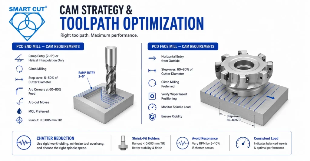
The performance gap between a correctly programmed PCD tool and an incorrectly programmed one can be significant. PCD edges that chip or wear prematurely are almost always the result of toolpath decisions, not material or tooling defects. Your CAM setup must account for these constraints before any test cut.
PCD End Mill — CAM Requirements
- Entry strategy: ramp entry at 2 to 5 degrees, or helical interpolation only. No direct Z-axis plunge.
- Milling direction: climb milling (not conventional) to minimize edge impact loading.
- Step-over: 5 to 50 percent of cutter diameter depending on roughing vs. finishing.
- Corner strategy: arc corner motion at reduced feed (60 to 80 percent) to prevent chip packing.
- Exit strategy: arc-out moves; avoid abrupt retract from the cut.
- Coolant: MQL preferred; flood acceptable for aluminum; dry cutting for composites and graphite.
- Runout tolerance: 0.005 mm TIR maximum for tight-tolerance finishing. Use shrink-fit holders.
PCD Face Mill — CAM Requirements
- Entry strategy: approach horizontally from outside the part boundary. Never ramp down into material.
- Step-over: 60 to 80 percent of cutter diameter for uniform surface finish; reduce to 40 percent for light finishing passes.
- Feed direction: ensure the majority of inserts are in climb milling configuration relative to part travel.
- Wiper positioning: confirm wiper inserts are correctly indexed per manufacturer specification before production.
- Spindle load monitoring: consistent load is the key indicator of balanced inserts and healthy insert condition.
- Fixture rigidity: any workpiece movement telegraphs directly to surface finish quality.
Chatter Reduction
Chatter in PCD milling applications almost always originates from insufficient workholding rigidity, excessive tool overhang, or spindle speed coinciding with a system resonance frequency. Shrink-fit holders provide significantly better runout control (below 0.003 mm TIR) compared to standard collets (0.005 to 0.015 mm TIR). When chatter persists, vary spindle speed by 5 to 10 percent in either direction while observing surface finish. If finish improves at a slightly different RPM, you have identified a resonance node — adjust your program to avoid it during production.
Real-World Application Examples
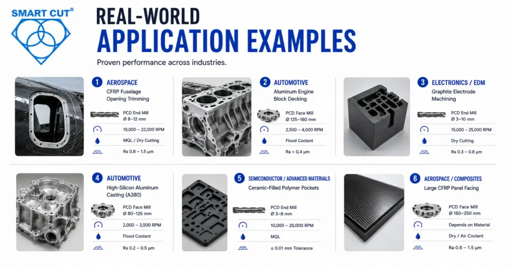
Aerospace — CFRP Fuselage Opening Trimming
Multi-axis routing of door and window cutouts in fuselage skin panels. Delamination and fiber pullout are zero-tolerance failure modes. PCD end mills (diameter 8 to 12 mm) at 18,000 to 22,000 RPM with MQL or dry cutting. Achieved Ra 0.8 to 1.5 microns at the trimmed edge.
For composite machining applications, visit UKAM’s composite industry page.
Automotive — Aluminum Engine Block Decking
Cylinder head mating surface must meet flatness of plus or minus 0.005 mm over the full block face with Ra below 0.4 microns. High production volumes require insert-swap maintenance — not off-site resharpening. PCD face mills (diameter 125 to 160 mm) at 2,500 to 4,000 RPM with flood coolant are standard in this application.
Electronics / EDM — Graphite Electrode Machining
Graphite is highly abrasive — carbide tools wear out in minutes under these conditions. PCD end mills achieve hundreds of electrodes per edge while holding tight dimensional tolerances critical to EDM spark gap geometry. Run dry at 15,000 to 25,000 RPM, diameter 3 to 10 mm, Ra 0.3 to 0.8 microns achievable.
Automotive — High-Silicon Aluminum Casting (A380)
Silicon particles in A380 alloy destroy carbide tooling rapidly. PCD face mills with silicon-resistant PCD grade maintain insert life 20 to 50 times longer than carbide while achieving mirror-quality finish on pump and transmission bodies. Typical parameters: diameter 80 to 125 mm, 2,000 to 3,500 RPM, flood coolant, Ra 0.2 to 0.5 microns.
Semiconductor / Advanced Materials — Ceramic-Filled Polymer Pockets
Ceramic filler content rapidly dulls conventional tooling. PCD end mills (diameter 3 to 8 mm) maintain edge sharpness through the abrasive matrix, holding plus or minus 0.01 mm on pocket dimensions across extended production runs at 10,000 to 20,000 RPM with MQL.
For semiconductor and advanced materials applications, see the semiconductor industry page.
Aerospace / Composites — Large CFRP Panel Facing
Composite structural panel surfaces require uniform thickness removal across widths exceeding 400 mm. A face mill at diameter 160 to 250 mm covers this in a single pass. An equivalent end mill strategy at 10 mm step-over would take 40 times the cycle time. Dry cutting or compressed air coolant, Ra 0.6 to 1.5 microns.
Tool Life, Maintenance, and Long-Term Cost
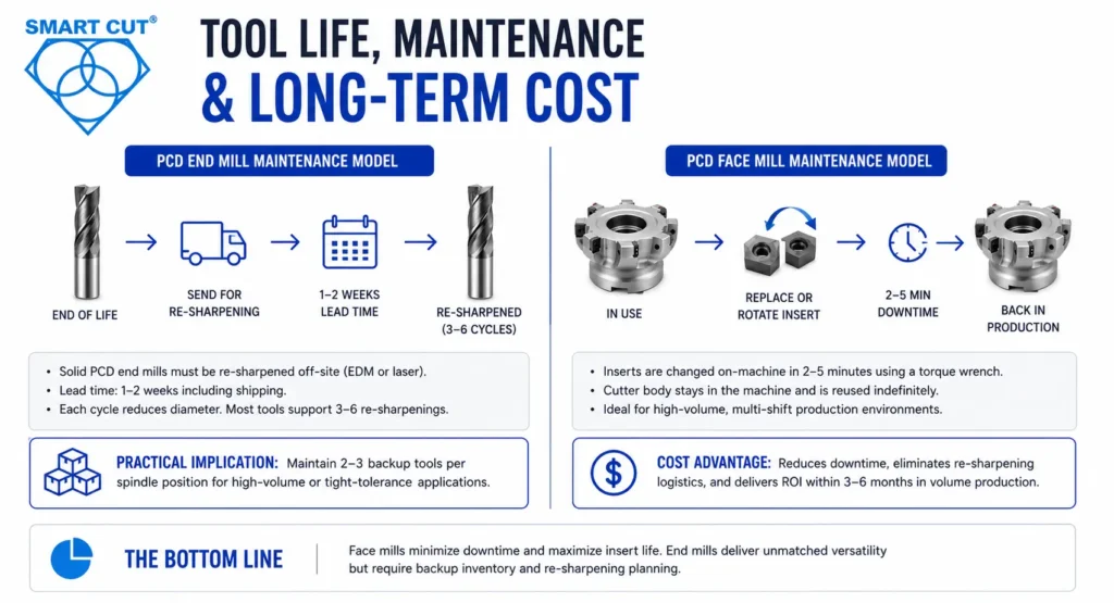
PCD End Mill Maintenance Model
When a solid PCD end mill reaches end of life, it must be removed and sent to a facility equipped with EDM or laser grinding to re-sharpen the diamond edge. Lead time including shipping is typically 1 to 2 weeks. Each re-sharpening cycle slightly reduces the tool diameter, eventually moving the tool outside acceptable tolerance range. Most tools support 3 to 6 re-sharpening cycles before the diameter reduction becomes a problem.
Practical implication: every PCD end mill application requires a backup tool inventory. Plan for 2 to 3 backup tools per active spindle position on high-volume or tight-tolerance applications.
PCD Face Mill Maintenance Model
A PCD face mill body never leaves the machine floor for routine maintenance. When an insert wears, the operator uses a standard torque wrench to remove the worn insert cartridge and replace or rotate it. Downtime is 2 to 5 minutes. The cutter body — the most expensive component — is reused indefinitely.
In a high-volume automotive or aerospace production line running multiple shifts, this maintenance model advantage can represent thousands of dollars per year in avoided downtime and resharpening logistics. The higher initial investment in a quality face mill body typically pays back within 3 to 6 months of volume production.
Table 4: Insert Life Comparison — PCD vs. Carbide on Aluminum
|
Problem |
Probable Cause |
Corrective Action |
Prevention |
|---|---|---|---|
|
Wheel glazing |
Bond too hard, concentration too low |
Specify softer bond grade, increase dress frequency |
Match bond grade to cutter hardness at specification stage |
|
Thermal cracking (cutter surface) |
Poor coolant delivery, glazed wheel |
Improve coolant pressure and nozzle position, dress wheel |
Verify coolant setup before every production run |
|
Interface chipping |
Excessive feed rate at transition zone |
Reduce feed by 50 to 70% before interface |
Program feed rate change at defined spindle load threshold |
|
Chatter marks |
Wheel imbalance |
Rebalance to G2.5 or G1.0 |
Balance check before every wheel installation |
|
Rapid wheel wear |
Incorrect diamond grade (too friable) |
Specify tougher crystal grade |
Confirm crystal friability for application before ordering |
|
Poor edge sharpness |
Wheel loading, dress interval too long |
Dress more frequently, verify coolant filtration |
Schedule dress intervals, do not wait for visible degradation |
|
Subsurface micro-cracking |
Excessive depth of cut or grinding force |
Reduce depth of cut, verify wheel balance |
Use cross-section inspection after parameter changes |
|
Inconsistent surface finish lot to lot |
Irregular dress interval or coolant concentration |
Standardize dress interval, check coolant concentration |
Use scheduled dressing, document and monitor coolant concentration |
Tool Selection Decision Framework
Use these five questions to drive tool specification before entering CAM programming. Changing tool type after toolpath development is expensive.
Question 1: What is the target feature geometry?
If the feature is an enclosed pocket, a slot, a cavity, or a profiled contour — the PCD end mill is the only option. If the feature is a broad, open flat surface — the face mill is the correct choice.
Question 2: What is the material?
Both tools work well in aluminum alloys, composites, copper, graphite, and other non-ferrous or non-metallic materials. PCD is chemically incompatible with ferrous metals. For hardened steel or cast iron, PCBN tooling is the correct choice.
Question 3: What surface finish is required?
For Ra values below 0.6 microns over a large area, a face mill with wiper inserts is the reliable path. For localized surface finish inside a pocket, a well-specified end mill with correct chip load management is appropriate.
Question 4: What is the production volume?
Low-volume or R&D work often favors the simpler end mill. High-volume production lines benefit significantly from the face mill insert-swap maintenance model and higher material removal rate.
Question 5: What does your CAM strategy allow?
Face mills require horizontal entry from outside the part boundary. End mills require ramped or helical entry into solid material. Both constraints must be incorporated into your toolpath design before committing to a tool specification.
Frequently Asked Questions
Technically possible for small areas, but inefficient. An end mill produces visible step-over marks across the faced surface and removes material at a fraction of the rate of a dedicated face mill. Not recommended for production environments requiring flat surface quality.
No. Face mills have no side-cutting geometry and the tool body cannot enter a cavity or cut a slot. For any enclosed or profiled geometry, an end mill is required.
Ferrous metals — steel, stainless steel, and cast iron — are chemically incompatible with PCD at cutting temperatures due to carbon diffusion into the iron. For hardened ferrous materials, PCBN is the correct superhard cutting material.
Use climb milling, not conventional milling. Avoid direct Z-axis plunging — use ramp or helical entry. Maintain correct chip load; under-feeding causes rubbing and premature wear. Ensure adequate coolant flow or minimum quantity lubrication. Use shrink-fit holders to minimize runout.
Determined by spindle power, machine rigidity, and block width. For most CNC machining centers, 80 to 160 mm is the practical range. Contact the UKAM engineering team with your machine specifications and part drawing for a specific recommendation.
Yes. Custom geometry, non-standard diameters, and application-specific PCD grades are all available through the custom tooling program. Engineering support is included from specification through delivery.
SMART CUT technology is UKAM’s proprietary manufacturing process that controls the variables — bond formulation, crystal orientation, grit distribution — that determine whether a superhard tool performs to specification or fails early. It is the engineering foundation behind the consistency and edge life that differentiates UKAM tooling from commodity alternatives.
About UKAM Industrial Superhard Tools
UKAM Industrial Superhard Tools is a U.S.-based manufacturer serving engineers, production facilities, and research institutions since 1990. We design and manufacture diamond and CBN tooling, and our engineering team works directly with customers to develop solutions for demanding applications where standard tooling falls short.
We have worked with Fortune 500 manufacturers, government research laboratories, and thousands of production environments across aerospace, automotive, electronics, semiconductor, and advanced materials industries.
For engineers in the composites industry, advanced ceramics, or semiconductor manufacturing, UKAM offers fully custom-manufactured solutions with direct engineering support.
Need a Tooling Recommendation?
Contact the UKAM engineering team to discuss your milling application, request a custom tool quotation, or access the full application library for precision superhard tooling.
Request an Engineering Consultation | Browse PCD & PCBN Tools | Custom Tooling Inquiry | View All Diamond Milling Tools
Trusted by Tens of Thousands of Manufacturers, Laboratories,
Research Institutions Worldwide Since 1990
American Based Manufacturer
Established in 1990
Custom manufacturing
RELATED ARTICLES

Whether in a factory for industrial production or in the research lab, testing lab, and inspection area of a university
The use of diamond tools in the manufacturing and precision machining industries, as well as in construction, research, etc., is essential.