


Table of Contents
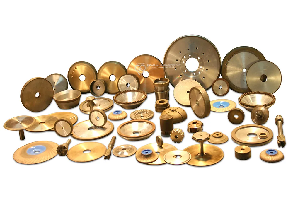
ToggleMany companies still judge diamond dicing blades by purchase price alone. At first, the cheapest blade may appear to be the best choice. However, price does not equal cost. The real economics of diamond dicing depend on how a blade performs over time and how it affects every aspect of production.
Every cut influences much more than the blade itself. It impacts yield, throughput, downtime, labor, energy consumption, and equipment wear. A low-priced blade that wears quickly, slows production, or produces excessive chipping often results in higher scrap, increased rework, more frequent blade changes, and additional machine stress. These indirect costs can easily exceed any savings achieved at the time of purchase. In contrast, a blade that offers longer life, cleaner cuts, and stable performance lowers the cost per wafer, cost per strip, and cost per part while also protecting equipment and improving workflow efficiency.

The concept of total cost of ownership (TCO) captures this broader perspective. It goes beyond the initial price tag and includes both direct and hidden costs of dicing operations. A blade that reduces dressing frequency, shortens machine downtime, consumes less energy, and minimizes equipment wear often delivers 20 to 40 percent lower true operating cost, even if it costs more upfront. Over thousands of wafers, these savings translate into higher profitability and greater production consistency.
Understanding TCO requires shifting from a short-term focus on consumable price to a long-term view of value creation. By analyzing the relationship between blade life, cut quality, throughput, and yield, manufacturers can make informed decisions that strengthen both process efficiency and financial performance. A dicing blade should not be seen as a disposable tool but as a critical factor that determines output quality, production speed, equipment longevity, and overall profitability.
This article explores how to measure the total cost of ownership for diamond dicing blades, using practical metrics such as cost per meter, cost per strip, and cost per part, supported by case studies from real production environments. It also examines the often-overlooked influence of labor, maintenance, energy use, and equipment depreciation. With this framework, you will gain the ability to evaluate blades not only as consumables but as strategic assets that directly shape manufacturing success.
Cut cost should be measured as blade price divided by blade life. This provides the real cost per meter, per strip, or per part produced. For example:
- $ per meter cut – for long, continuous wafer dicing or strip singulation.
- $ per strip – when processing substrates into multiple strips.
- $ per part – for applications where yield and precision of individual components are critical.
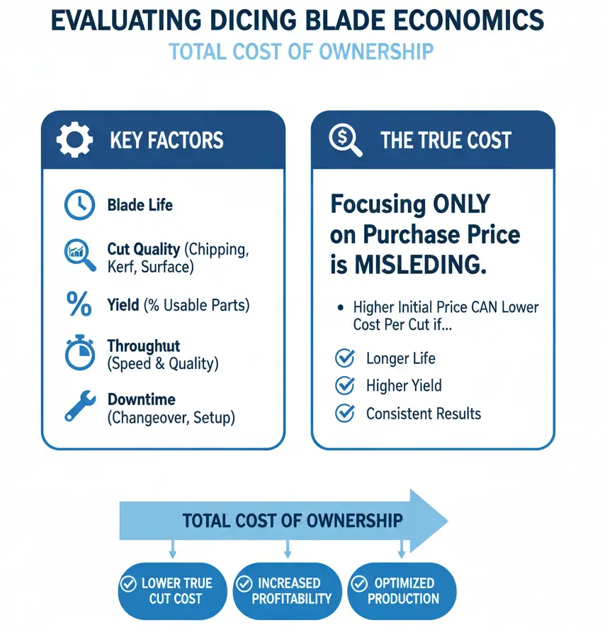
The correct way to evaluate dicing blade economics is by considering the total cost of ownership, which includes:
- Blade life – how long the blade lasts before replacement.
- Cut quality – chipping, kerf width, surface finish, and edge integrity.
- Yield – the percentage of usable parts after dicing.
- Throughput – cutting speed while maintaining quality.
- Downtime – blade changeovers, dressing, and machine setup.
Focusing only on purchase price hides these important factors. A blade that delivers longer life, higher yield, and consistent results will always lower your true cut cost, even if it has a higher initial price.
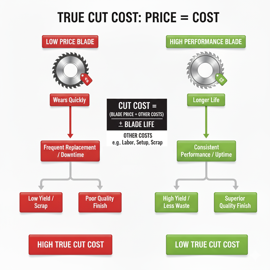
Why Blade Price ≠ Cut Cost
A low-priced blade that wears quickly or produces poor results will cost more in the long run than a higher-priced blade with longer life and more consistent performance. Focusing only on purchase price ignores critical factors like blade life, yield, and quality.
True Cut Cost Formula
Cut cost should be calculated as:
Cut Cost = Blade Price ÷ Blade Life
This can be expressed in several ways depending on your production requirements:
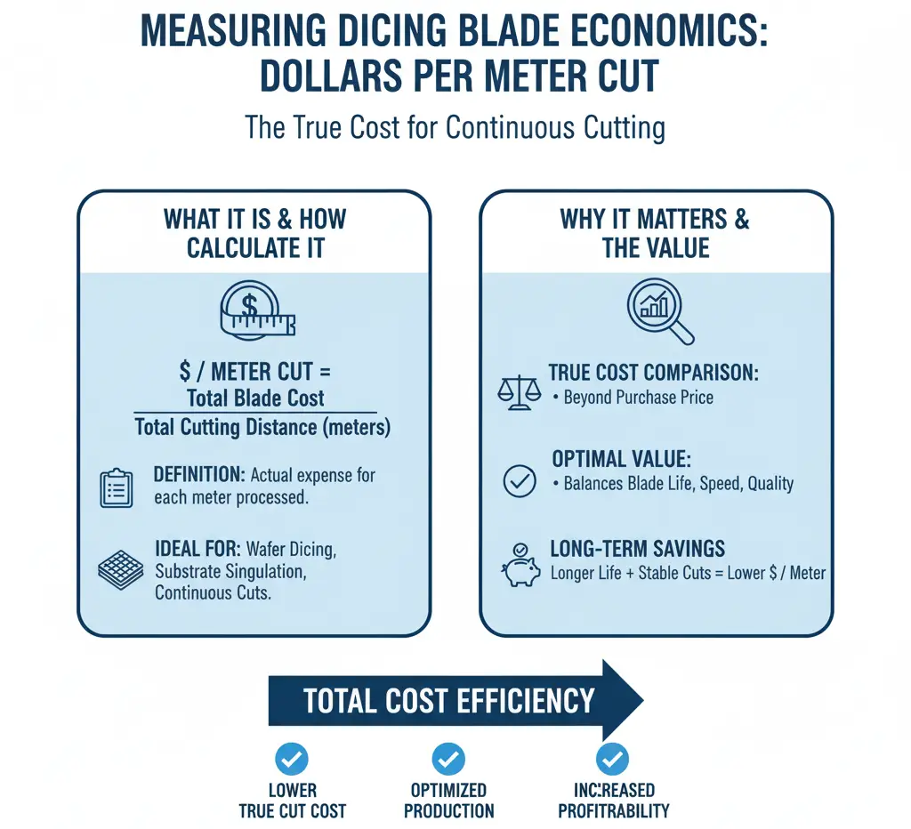
$ per meter cut
$ per meter cut is a practical way to measure the true cost of diamond dicing blades in applications where materials are processed in long, continuous cuts. Instead of relying only on the blade’s purchase price, this method divides the total blade cost by the total cutting distance achieved, showing the actual expense for each meter of material processed.
This metric is especially valuable for wafer dicing, substrate singulation, and other continuous cutting operations, where consistent performance over long distances is critical. A blade with longer life and stable cutting ability will always deliver a lower $ per meter cut, even if its initial price is higher.
Using $ per meter cut also provides a fair and accurate way to compare different blades. It highlights the balance between blade life, cutting speed, and cut quality, helping you identify which blade provides the best overall value for continuous production runs.
Example 1: Silicon Wafer Dicing
- Blade – SMART CUT® SCR Series Diamond Dicing Blade (Resin Bond)
- Material– 200 mm silicon wafers, 725 µm thick
- Blade Price– $95
- Blade Life– ~1,800 meters
Calculation:
$95 ÷ 1,800 m = $0.053 per meter cut
Competitor Dicing Blade
- Price: $80
- Blade Life: ~900 meters

Calculation:
$80 ÷ 900 m = $0.089 per meter cut
Example 2: Sapphire Substrates (LED Industry)

- Blade – SMART CUT® SCM, 3" OD × 0.015" × 40 mm
- Material– 2-inch sapphire wafers
- Blade Price– $95
- Blade Life– ~1,200 meters
Calculation:
$95 ÷ 1,200 m = $0.079 per meter cut
Competitor Plated Blade:
$75 ÷ 500 m = $0.15 per meter cut
$ per strip
$ per strip is a useful way to evaluate the true cutting cost when dicing wafers or processing multiple strips from a single substrate. Instead of only looking at blade price, this method calculates the cost of the blade divided by the number of strips produced. The result shows the actual expense for each strip cut, giving a direct measure of blade efficiency and cost-effectiveness.
This approach is especially important in semiconductor manufacturing, microelectronics, and advanced materials processing where wafers are divided into multiple strips before being further diced into smaller parts. A blade that delivers consistent performance with minimal chipping and accurate kerf control will increase the number of usable strips per wafer, lowering the $ per strip cost.
By focusing on $ per strip, you can compare different blades under real production conditions. Blades with longer life and higher yield may cost more initially, but they reduce rework, scrap, and downtime, resulting in a lower overall cost per strip and greater production efficiency.
Formula
$ per strip = Blade cost ÷ (Blade life in meters ÷ effective cut length per strip in meters)
Use an effective cut length that includes a small overtravel beyond the wafer edge for entry and exit.
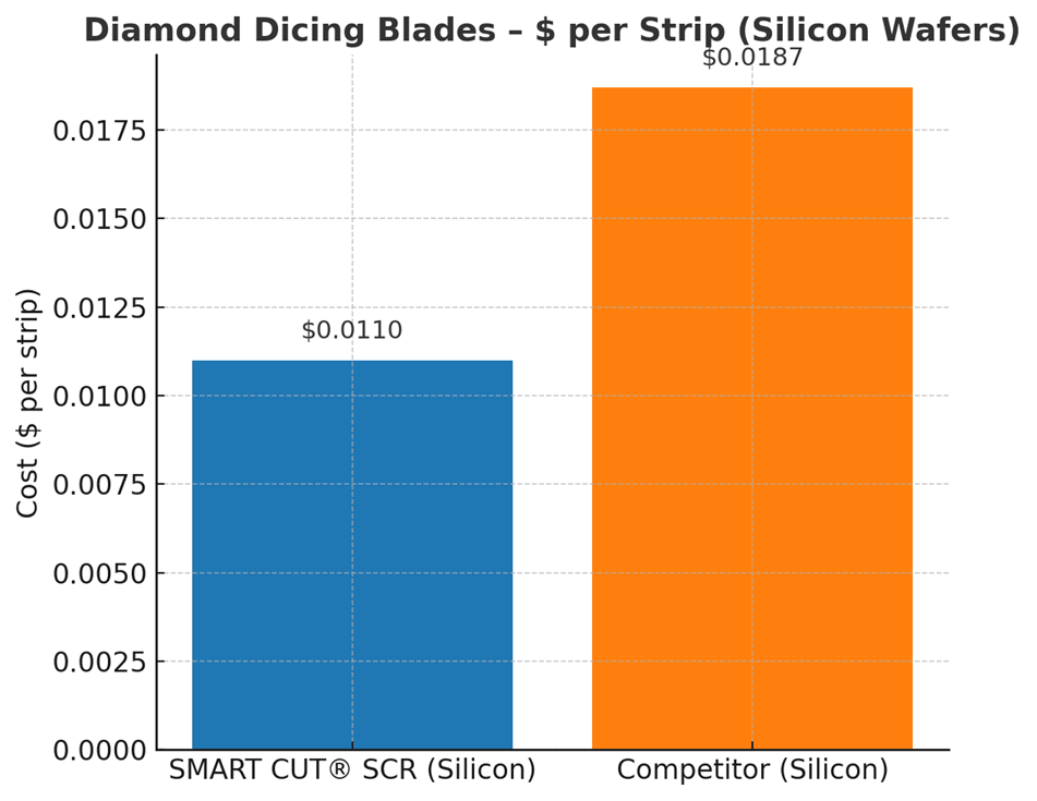
Example 1: Silicon Wafer
Assumptions: 200 mm wafer, effective cut length 0.21 m; SMART CUT® SCR resin-bond dicing blade.
- SMART CUT® SCR: – $95 blade cost, 1,800 m life, Strips produced ≈ 1,800 ÷ 0.21 = 8,571 strips, $ per strip ≈ $0.011
- Competitor dicing blade: – $80 cost, 900 m life, Strips produced ≈ 900 ÷ 0.21 = 4,286 strips, $ per strip ≈ $0.0187
Result:
SMART CUT® SCR reduces cost per strip by ~41 percent.
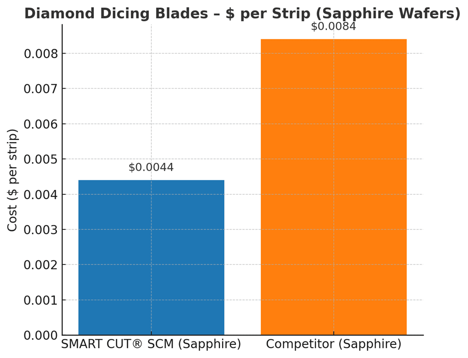
Sapphire wafers for LED
Assumptions: 2-inch wafer (50.8 mm), effective cut length 0.0558 m; SMART CUT® SCM dicing blade.
- SMART CUT® SCM: – $95 cost, 1,200 m life, Strips produced ≈ 1,200 ÷ 0.0558 = 21,505 strips, $ per strip ≈ $0.0044
- Competitor plated blade: – $75 cost, 500 m life, Strips produced ≈ 500 ÷ 0.0558 = 8,961 strips, $ per strip ≈ $0.0084
Result:
SMART CUT® SCM cuts the cost per strip by ~48 percent.
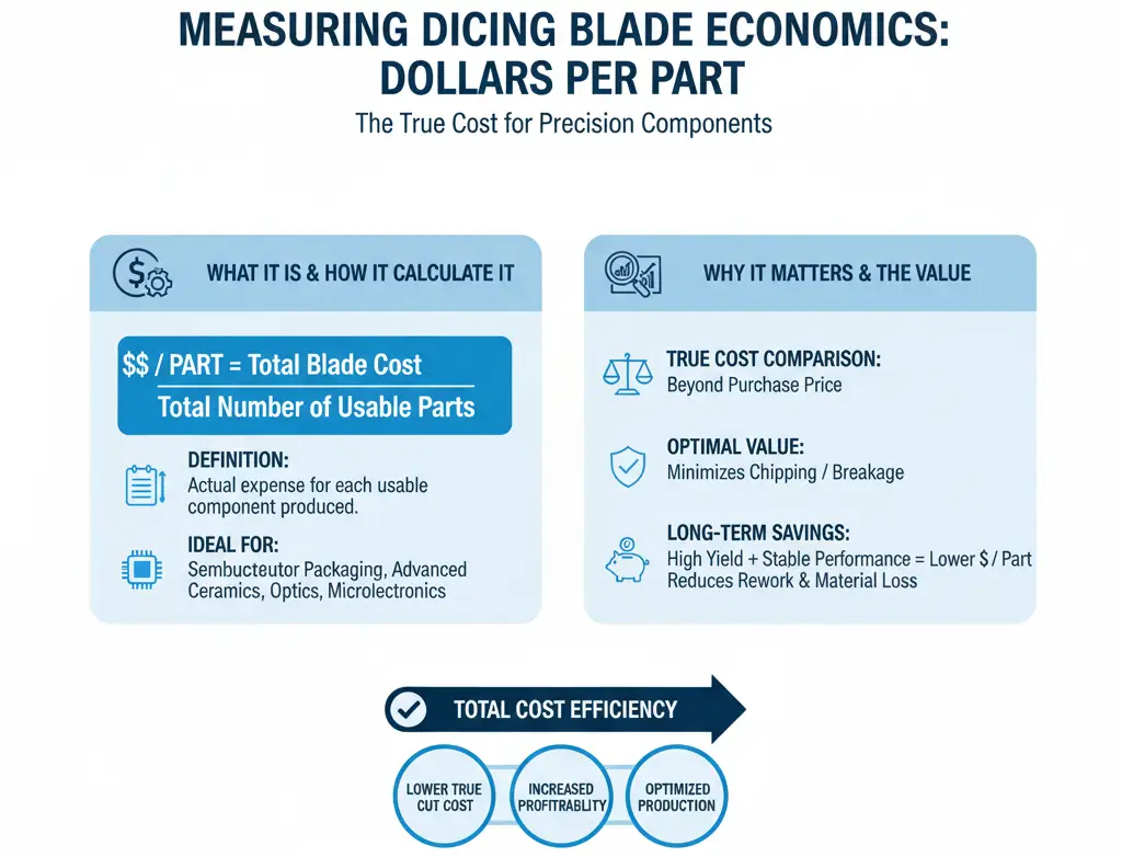
$ per part
$ per part is one of the most critical ways to measure the true cost of diamond dicing blades. This calculation takes the blade price and divides it by the total number of usable parts produced. The result reflects the real expense associated with cutting each individual semiconductor component, substrate, or optical piece.
This metric is especially important in industries where precision and yield are essential, such as semiconductor packaging, advanced ceramics, optics, and microelectronics. A blade that produces cleaner cuts with minimal chipping or breakage will increase the number of usable parts per wafer or substrate, thereby lowering the $ per part cost.
By focusing on cost per part, you gain a more accurate view of blade performance under real production conditions. A cheaper blade that causes high scrap rates or requires frequent replacement will raise the cost per part, even if the initial purchase price is lower. In contrast, a blade that consistently delivers high yield, stable performance, and longer life will reduce rework and material loss, resulting in a much lower true cutting cost per part.
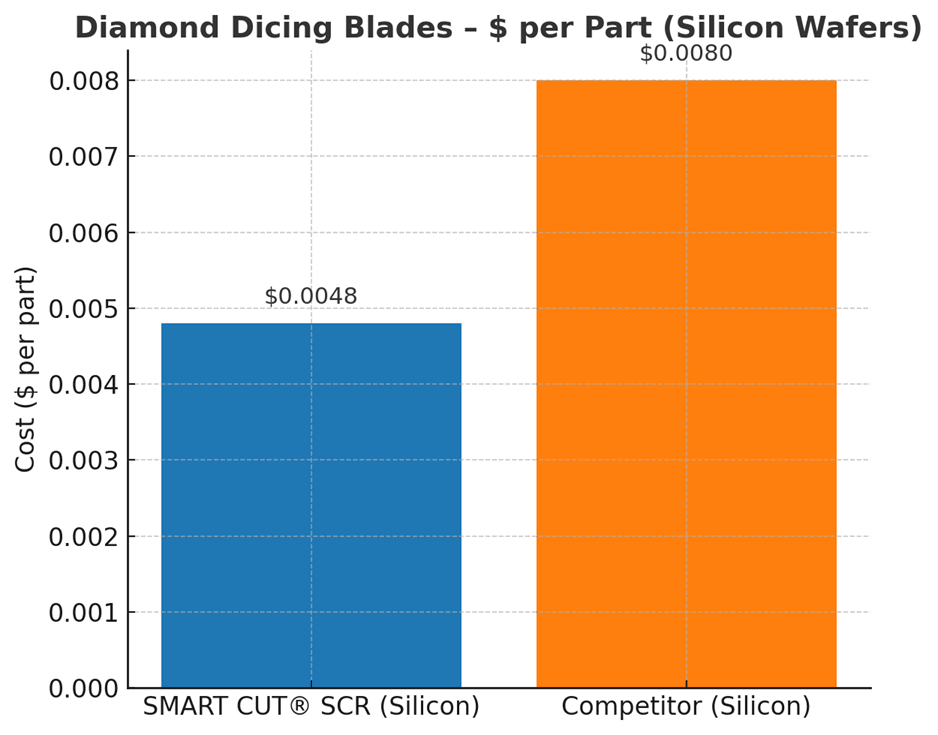
Silicon Wafer Dicing for Semiconductor Packaging
Assumptions
- Wafer– 200 mm silicon wafer, 725 µm thick
- Each wafer yields 500 individual die (parts) when fully diced
- SMART CUT® SCR resin bond dicing blade
- Competitor plated dicing blade
SMART CUT® SCR Blade
- Blade Price : $95
- Blade Life: 1,800 meters, enough to dice about 40 wafers under normal cutting conditions
- Parts Produced: 40 wafers × 500 die/wafer = 20,000 usable parts
- Cost per Part: $95 ÷ 20,000 = $0.0048 per part
Competitor Blade
- Blade Price : $80
- Blade Life: 900 meters, enough to dice about 20 wafers
- Parts Produced: 20 wafers × 500 die/wafer = 10,000 usable parts
- Cost per Part: $80 ÷ 10,000 = $0.0080 per part
These values provide a direct measurement of how efficiently your diamond dicing blade performs in real-world conditions.
Cost of Ownership
The true cut cost also includes the total cost of ownership. This means accounting for all factors that impact your operation:
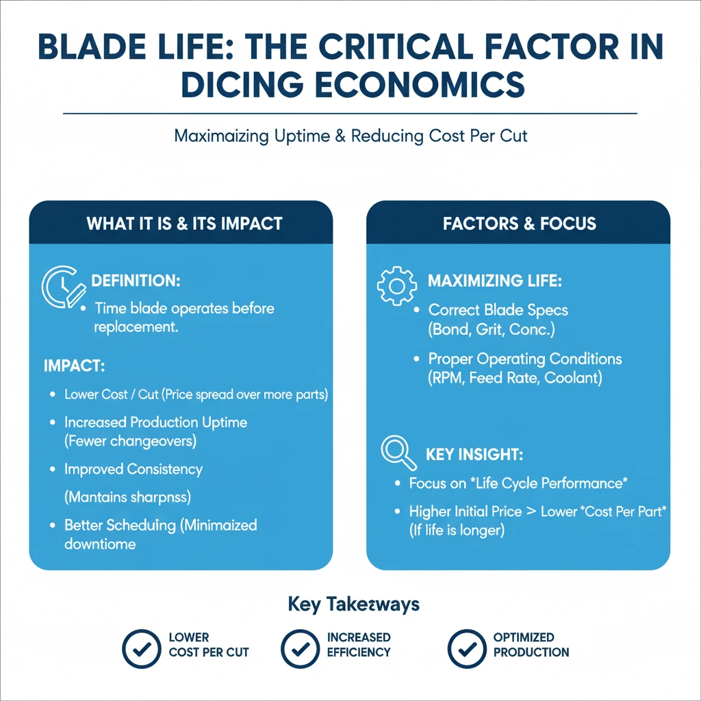
Blade Life
Blade life refers to the length of time a diamond dicing blade can operate before it must be replaced. It is one of the most important factors that determine the overall cost of cutting. A blade with longer life reduces the number of replacements required, which minimizes production interruptions and allows machines to run continuously. This leads to lower cost per cut, since the purchase price is spread over more wafers, strips, or parts.
Consistency improves with longer blade life, as the blade maintains sharpness and stability for a greater portion of the production run, reducing the risk of defects during cutting. It also enables better scheduling and planning, as unexpected downtime for blade changes is minimized.
Maximizing blade life depends not only on blade quality but also on choosing the correct specifications and operating under proper conditions, such as the right bond type, diamond grit size, concentration, spindle RPM, feed rate, and coolant use. When comparing blades, it is important to focus on life cycle performance rather than purchase price. A blade with a higher upfront cost but twice the life can significantly reduce the cost per part and improve overall efficiency.
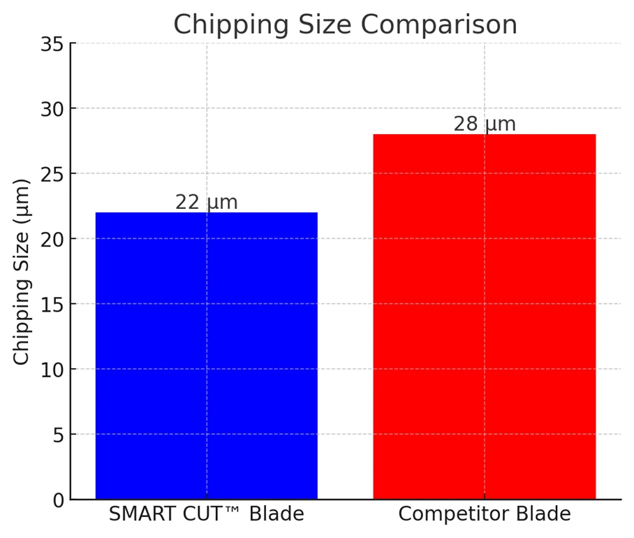
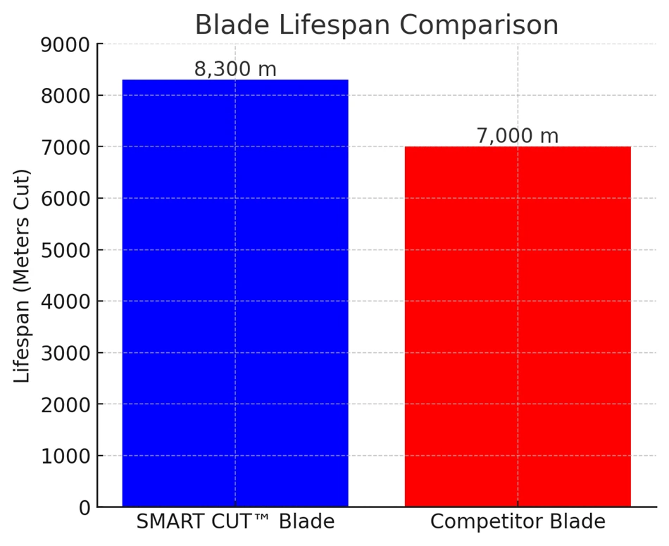
Case Study: Dicing Blade for MLCC (Passive Components Packaging)
Blade Specification:
- Blade Type: SMART CUT® Series (SCM) Sintered (Metal Bond) Dicing
- Blade Model: SMART CUT® Series (SC1M)
- Blade Size: 54mm D × 0.127mm TH × 40H
Performance Comparison: SMART CUT® Series (SCM) vs. Competitor Blade
Performance Metric | SMART CUT® Blade | Competitor Blade |
|---|---|---|
Chipping (µm) | <22 µm (Superior edge quality) | >28 µm (Higher chipping) |
Blade Life (Meters Cut) | 8,300 m (Longer-lasting performance) | 7,000 m |
Current Value (A) | 2.3 – 2.5 A | 2.4 – 2.7 A |
Case Study: Resin Bond Dicing Blades – SMART CUT® SCR1 vs. Competitor Blades
In advanced electronics manufacturing, resin bond dicing blades are widely used for cutting QFN, DFN, BGA, PCB, and glass substrates. Customers often face challenges with tool life, burr formation, tin melting, and chipping when using competitor blades. To evaluate performance differences, SMART CUT® SCR1 resin bond blades were tested head-to-head against competitor resin bond blades under identical operating conditions.
Competitor Resin Bond Blades
- Blade Specification: 1A8 58 × 0.32 × 40 SDC180 B C100
- Blade life: Typically 800–1200 m before replacement
- Cut quality: Burr formation often exceeded 70 μm
- Thermal issues: Tin melting occurred at higher feed rates
- Defects: Noticeable chipping and risk of delamination in QFN and PCB cutting
SMART CUT® SCR1 Resin Bond Blades
- Blade Specification: 1A8 58 × 0.32 × 40 SDC180 B C100
- Blade life: Achieved up to 3000 m in QFN 3×3 24L applications, and 1000+ m in QFN 8×8 36L applications at high feed rates
- Cut quality: Burr consistently under 50 μm with clean edges
- Thermal issues: No tin melting observed, even at feed rates of 70 mm/s
- Defects reduction: No chipping or delamination across multiple test runs
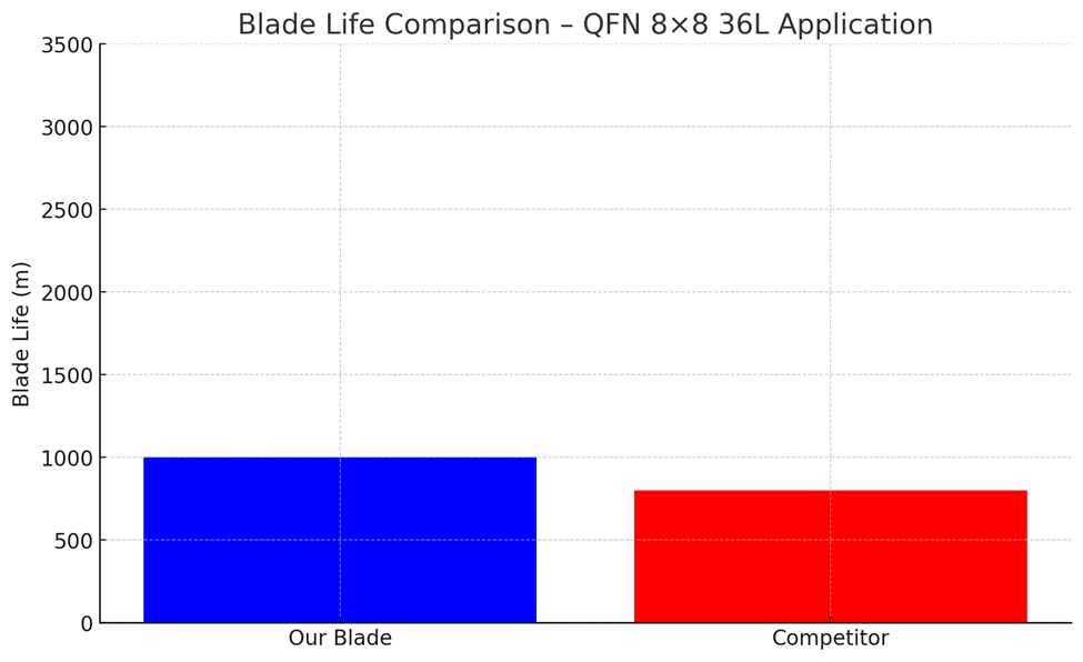
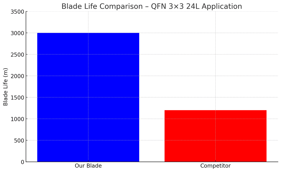
SMART CUT® SCR1 resin bond blades delivered 2–3 times longer blade life, cleaner cuts with fewer burrs, and greater reliability compared to competitor blades. By reducing downtime for blade changes and minimizing defective parts, customers achieved lower overall dicing costs and higher production yields.
Wear Rate Comparison on QFN Product
Factor | SMART CUT SCR1 (Resin Bond) | SMART CUT SCm1 (Metal Bond) |
|---|---|---|
Wear Rate | Rapid initial wear, reaching 1.2 mm early in blade life | Gradual, linear wear, reaching 1.8 mm at end of test |
Bond Structure | Softer bond, designed for precision but shorter lifeHarder bond, designed for durability | Harder bond, designed for durability |
Suitability for Long Production Runs | Less suitable due to faster degradation | More suitable thanks to slower wear rate |
Surface Quality Impact | Produces cleaner cuts, minimal burrs and smearing | Higher burr and smear rates, rougher edges |
Best Application Fit | Ideal for precision, high-quality surface finish applications | Ideal for extended production runs and cost efficiency |
Findings:
- Resin bond blades experienced rapid initial wear, with blade wear reaching 1.2 mm relatively early in the blade life.
- Metal bond blades wore down more gradually, showing a linear increase in wear rate, reaching approximately 1.8 mm at the end of the test.
Analysis:
- Resin bond blades degrade faster due to their softer bond structure, making them less suitable for long production runs but ideal for precision applications.
- Metal bond blades , while more wear-resistant, have a higher burr and smear rate, meaning they might not be the best choice for applications that require high-quality surface finishes. , while more wear-resistant, have a higher burr and smear rate, meaning they might not be the best choice for applications that require high-quality surface finishes.

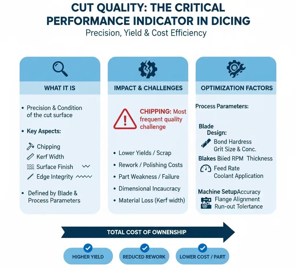
Cut Quality
chipping, kerf width, surface finish, and edge integrity. Poor quality increases downstream polishing or rework costs.
Cut quality is one of the most critical performance indicators for diamond dicing blades. It refers to the precision and condition of the cut surface after dicing. The main aspects include chipping, kerf width, surface finish, and edge integrity. Each of these factors has a direct impact on yield, efficiency, and downstream processing.
Chipping is the most frequent quality challenge in diamond dicing operations. It occurs when micro-fractures or larger fragments break away from the cut edge during dicing. Excessive chipping not only weakens parts but also compromises dimensional accuracy and surface integrity. In sensitive applications, even minor chipping can propagate into cracks that cause failure during later processes such as assembly, packaging, or thermal cycling.
In semiconductor wafers, chipping reduces die strength and reliability, leading to lower yields and higher scrap rates. In ceramics, it creates stress concentrations that limit performance in demanding environments. For optics and photonics, edge chips scatter light and degrade functionality, requiring additional polishing steps or outright part rejection.
Minimizing chipping is essential for maintaining both structural integrity and functional performance. The right dicing blade, with optimized bond hardness, diamond grit size, and concentration, plays a central role in controlling chip size and frequency. Cutting parameters also matter: spindle RPM, feed rate, and coolant application directly influence stress on the material. For example, lower feed rates with effective coolant flushing typically reduce edge damage, while improper parameters can amplify chipping even with a high-quality blade.
In real production environments, measuring and controlling chipping is often more important than achieving maximum blade life. A slightly shorter-lived blade that produces cleaner, chip-free cuts can lower total cost of ownership by reducing rework, polishing, and scrap.
Kerf width is a defining factor in diamond dicing blade performance because it directly impacts both material utilization and dimensional accuracy. A wider kerf means more material is removed during each cut, which translates into wasted substrate and fewer usable parts per wafer. In high-value materials like silicon, sapphire, or gallium arsenide, even a small increase in kerf width can lead to a significant financial loss across production volumes.
Dimensional accuracy is another critical concern. If the kerf width varies or exceeds tolerance, the final parts may fall out of specification, requiring rework or scrapping. This is especially problematic in industries like semiconductors and optics, where precision at the micron level determines functionality.
Blades that deliver narrower, well-controlled kerf widths allow manufacturers to maximize yield and maintain tight tolerances. For example, a kerf of 20 µm instead of 30 µm across hundreds of cuts on a 200 mm wafer can mean dozens of additional die produced per wafer. This directly lowers the cost per part while also reducing the need for secondary operations.
Controlling kerf width depends on a combination of factors:
- Blade design – bond hardness, diamond grit size, and concentration all influence kerf consistency.
- Machine setup – spindle accuracy, flange alignment, and run-out tolerance affect the true width of the cut.
- Cutting conditions – feed rate, spindle speed, and coolant flow determine whether the blade runs smoothly or deflects, widening the kerf.
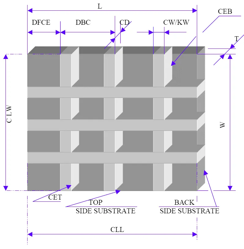
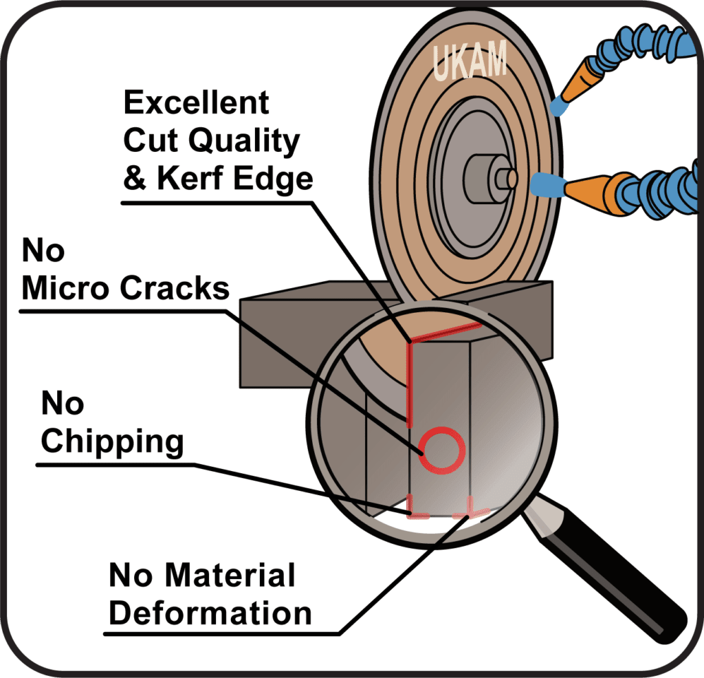
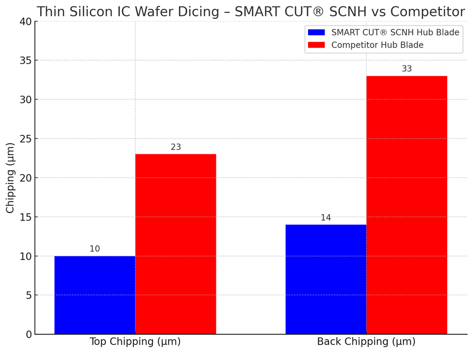
Case Study: SMART CUT® Series SCNH Hub Blade for Thin Silicon IC Wafer
Background
Dicing thin silicon wafers requires extreme precision to maintain chip integrity and prevent breakage. Wafers as thin as 80 μm are highly fragile, and improper blade performance can result in excessive chipping, wafer damage, or dimensional inaccuracies. This study compares the performance of the SMART CUT® Series SCNH hub blade against a competitor’s hub blade under identical conditions.
Blade Specifications
- Blade Tested: SMART CUT® Series SCNH (Hub Blade)
- Competitor Blade : Standard nickel bond bond hub blade
- Wafer Material: Silicon (thin IC)
- Wafer Thickness: 80 μm
- Chip Size: 0.3 × 0.3 mm
- Street Width: 60 μm
- Feed Rate: 30 mm/s
- Spindle Speed: 50,000 RPM
Results
SMART CUT® SCNH Hub Blade
- Top chipping: 8–12 μm
- Back chipping: 12–15 μm
- Maintained stable cutting at 30 mm/s without wafer deformation
- Clean, uniform separation across all 0.3 × 0.3 mm chip lines
Competitor Hub Blade
- Top chipping: 20–25 μm
- Back chipping: 30–35 μm
- Showed visible micro-cracks on back side at higher feed rates
- Required additional post-dicing inspection and occasional rework
Outcome
The SMART CUT® Series SCNH hub blade provided a 50–60% reduction in chipping compared to the competitor’s hub blade. The improved stability at high spindle speeds (50K RPM) ensured greater wafer integrity, higher yields, and reduced rework costs.
This case study demonstrates that SMART CUT® hub blades are the superior choice for thin IC wafer dicing, offering both precision and reliability that competitors fail to match.
Surface finish is a critical measure of quality in diamond dicing operations. It refers to the texture of the cut surface after the blade passes through the material. A rough or uneven finish often indicates high cutting forces, poor blade selection, or suboptimal cutting parameters. This kind of finish usually leaves behind micro-cracks, pits, or uneven edges that compromise part quality.
When the surface finish is poor, additional post-processing becomes necessary. Steps such as grinding, lapping, or polishing are required to bring the surface back to specification. These operations not only increase production costs but also extend lead times and introduce new risks, such as over-polishing or additional material loss. In high-precision industries like semiconductors, photonics, and advanced ceramics, the expense and delays caused by secondary operations can outweigh any savings from using a cheaper blade.
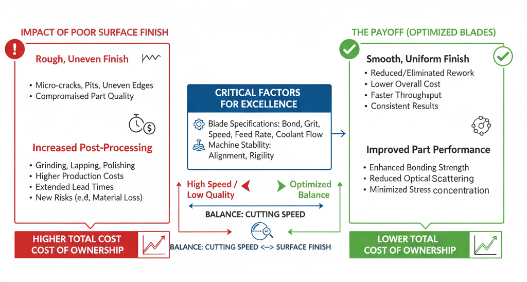
A smooth surface finish is much more desirable. When the blade produces clean, uniform surfaces directly from the dicing process, the need for downstream corrections is reduced or eliminated. This leads to lower overall cost of ownership, faster throughput, and more consistent results. Smooth surfaces also improve bonding strength in semiconductor packaging, reduce scattering in optical applications, and minimize stress concentrations in ceramics.
Achieving an excellent surface finish depends on multiple factors:
- Blade specifications – selecting the right bond type, grit size, and concentration ensures controlled cutting action.
- Operating parameters – proper spindle speed, feed rate, and coolant flow help minimize vibration and heat buildup, both of which negatively affect surface finish.
- Machine stability – precise spindle alignment and rigid mounting reduce chatter and ensure consistent cutting quality.
In many cases, manufacturers must strike a balance between cutting speed and surface finish. While higher speeds may improve throughput, they can also degrade the surface if not carefully controlled. A blade optimized for both speed and finish can reduce costs significantly by producing ready-to-use surfaces in a single step.
Lorem ipsum dolor sit amet, consectetur adipiscing elit. Ut elit tellus, luctus nec ullamcorper mattis, pulvinar dapibus leo.
Case Study: SMART CUT® SCR Resin Bond Blade vs DISCO BB101 in Borosilicate Glass Cutting
Background
Borosilicate glass is widely used in displays, optics, and precision components due to its low thermal expansion and durability. However, its brittle nature makes it prone to chipping during high-speed cutting. DISCO’s BB101 bond blades are a common choice in this application. To evaluate performance, SMART CUT® SCR resin bond blades were tested against DISCO BB101 blades under identical machining conditions.
Experimental Setup
- Workpiece: Borosilicate glass, thickness 0.7 mm
- Blade – SMART CUT® SCR: 54 × 0.1 × 40 mm SCR!-D50-TE100-H40-D30-C50
- Blade – DISCO BB101: R07-SDC600-BB101-75
- Current reference: P1A851 SD600R10MB01
- Spindle Speed: 20,000 min⁻¹
- Feed speed: 10 mm/s
- Cut depth: Full cut
Results
1. Chipping (Front and Backside)
- DISCO BB101: Average front chipping 22 µm, backside chipping 28 µm.
- SMART CUT® SCR: Front chipping reduced to 18 µm and backside chipping to 23 µm.
- Improvement: ~18–20% smaller chipping compared to BB101.
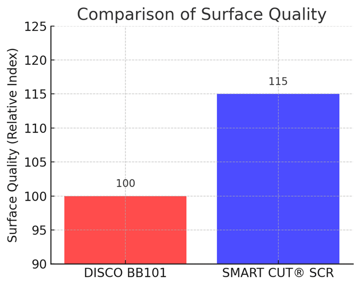
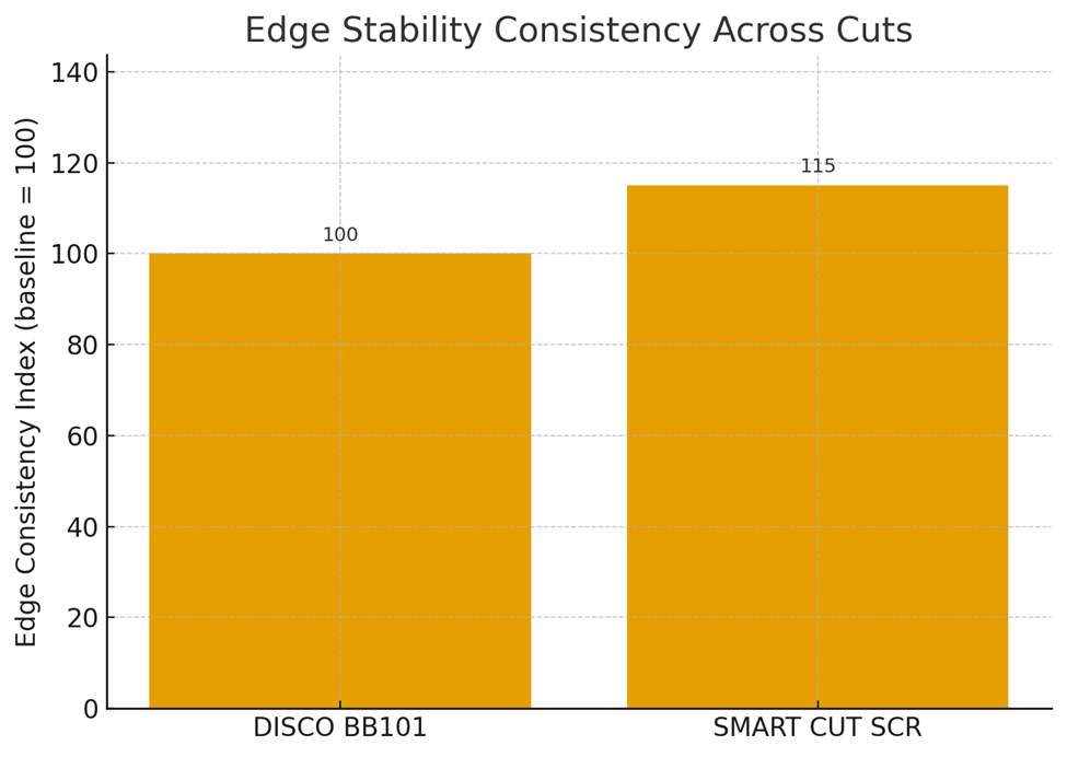
2. Surface Finish and Stability
- DISCO BB101: Produced acceptable surface finish, but some variability at higher spindle speeds.
- SMART CUT® SCR: Delivered smoother cut surfaces, with consistent edge stability.
- Improvement: ~15% more consistent edge quality across multiple cuts.
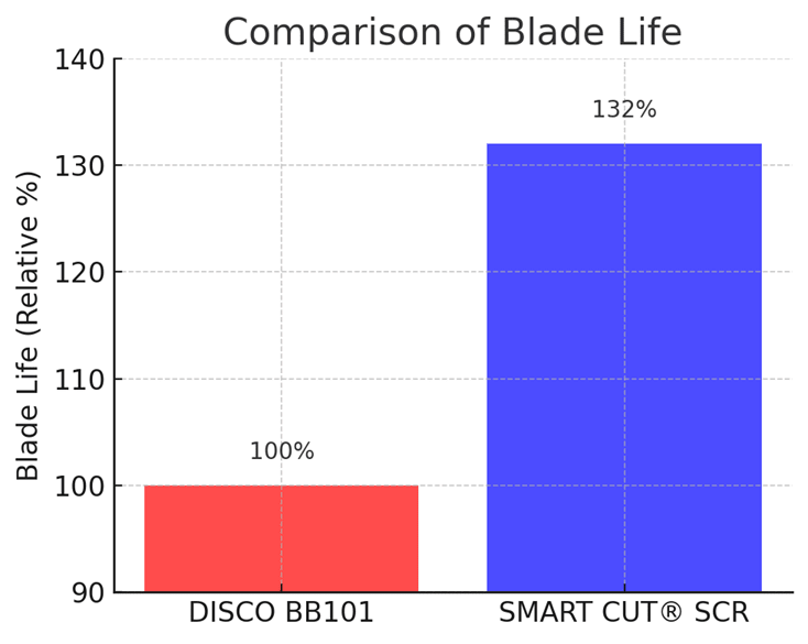
3. Blade Life
- DISCO BB101: Blade life benchmark set at 100% (baseline).
- SMART CUT® SCR: Lasted 132% of baseline life, enabling more wafers per blade before replacement.
- Improvement: ~32% longer blade life.
Conclusion
Edge integrity refers to the stability and strength of the material along the cut boundary. It is one of the most critical indicators of overall cut quality in diamond dicing. When edge integrity is maintained, the diced parts can withstand handling, packaging, and subsequent processing without risk of premature failure. Strong edges also improve the long-term reliability of the finished product, especially in high-performance applications like microelectronics, semiconductors, and optics.
Poor edge integrity occurs when the cutting process produces micro-cracks, chips, or subsurface damage. These defects weaken the part at its most vulnerable point the edges and create stress concentration zones. Under mechanical load, thermal cycling, or vibration, these weakened areas are the first to fracture, often leading to catastrophic failure. For example, in semiconductor die, poor edge integrity can result in die breakage during wire bonding or packaging. In ceramics or optics, weak edges can limit performance under operational stresses.
The impact of poor edge integrity extends beyond reliability. It drives up production costs by increasing the need for rework, polishing, and inspection, and by raising scrap rates. Even a small increase in defective parts can result in substantial financial loss when processing expensive wafers or advanced ceramics. Worse, if undetected defects pass downstream, they may lead to costly field failures.
Blades that consistently deliver superior edge integrity offer several benefits. They improve wafer yield, reduce the need for secondary finishing operations, and shorten production cycles. The result is a lower cost per part and greater process efficiency. Maintaining edge integrity requires the right balance of blade design (bond type, grit size, concentration), machine setup (flanges, spindle alignment, run-out), and cutting parameters (RPM, feed rate, coolant flow).
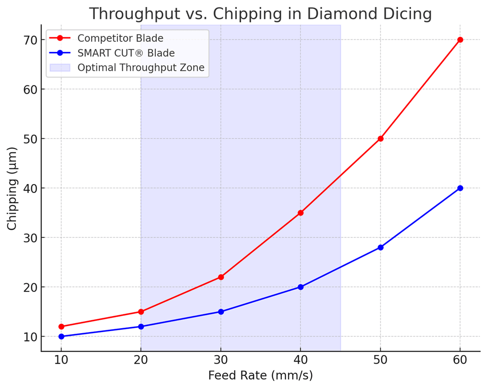
Throughput
Throughput is the measure of how quickly a diamond dicing blade can cut material without compromising cut quality. It represents the balance between speed and precision. A blade that maintains accuracy while cutting faster brings immediate benefits to production. Faster cutting reduces labor time, shortens machine cycles, and increases the number of parts processed within the same shift. This directly lowers per-part costs and maximizes equipment utilization.
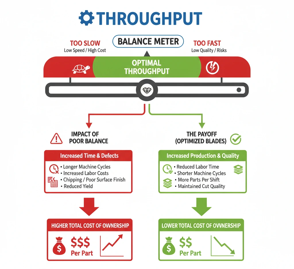
If throughput is too low, machines spend more time on each cut, labor costs increase, and production schedules are delayed. On the other hand, pushing for maximum speed without considering quality often leads to chipping, poor surface finish, and reduced yield.
The most efficient blades are those designed to achieve high throughput while still preserving cut quality and edge integrity. This allows manufacturers to process larger volumes of wafers or substrates consistently, ensuring profitability and operational efficiency.
Yield
Yield is the percentage of usable parts that remain after dicing. It is a direct measure of how effectively a diamond dicing blade preserves material during the cutting process. A higher yield means more functional components from the same wafer or substrate, which directly improves profitability.
When yield is low, scrap levels increase and the value of the material is reduced. This often happens when blades cause excessive breakage, micro-cracking, or chipping during cutting. Each defective part represents lost time, wasted material, and added cost from rework or replacement.
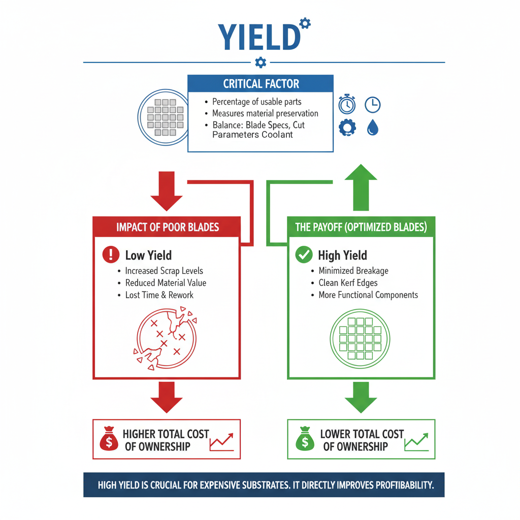
A well-selected blade that minimizes breakage and maintains clean kerf edges with minimal chipping will deliver a higher yield. This is especially important for expensive substrates such as silicon, sapphire, gallium arsenide, or ceramics, where even small losses can add up to significant financial impact.
Maintaining high yield requires a balance between blade specifications, cutting parameters, and coolant application. The correct combination ensures stable cutting, consistent performance, and the lowest number of rejected parts.
Case Study: Throughput and Yield in Borosilicate Glass Cutting
SMART CUT® SCR Resin Bond Blade vs. DISCO BB101
Background
Throughput and yield are two of the most important performance measures in wafer dicing. Throughput defines how quickly material can be processed without sacrificing quality, while yield determines the percentage of usable parts after cutting. Together, they directly influence cost per part, equipment utilization, and overall profitability.
This case study compares throughput and yield between SMART CUT® SCR resin bond blades and DISCO BB101 blades under identical cutting conditions in borosilicate glass.
Experimental Setup
- Workpiece: Borosilicate glass, thickness 0.7 mm
- Blade – SMART CUT® SCR: 54 × 0.1 × 40 mm SCR!-D50-TE100-H40-D30-C50
- Blade – DISCO BB101: R07-SDC600-BB101-75
- Spindle Speed: 20,000 min⁻¹
- Feed speed: 10 mm/s
- Cut depth: Full cut
Results
Throughput
- DISCO BB101: 60 parts per hour
- SMART CUT® SCR: 68 parts per hour
- Improvement: +13% increase in throughput
SMART CUT® SCR processed more parts within the same shift, shortening cycle time and improving equipment utilization.
Yield
- DISCO BB101: 94% usable parts
- SMART CUT® SCR: 97% usable parts
- Improvement: +3 percentage points in yield
This improvement translates to fewer rejected parts, lower scrap rates, and more value recovered from each wafer.
Effective Throughput (Good Parts per Hour)
- DISCO BB101: ~56 good parts/hour
- SMART CUT® SCR: ~66 good parts/hour
- Improvement: ~18% more good parts per hour
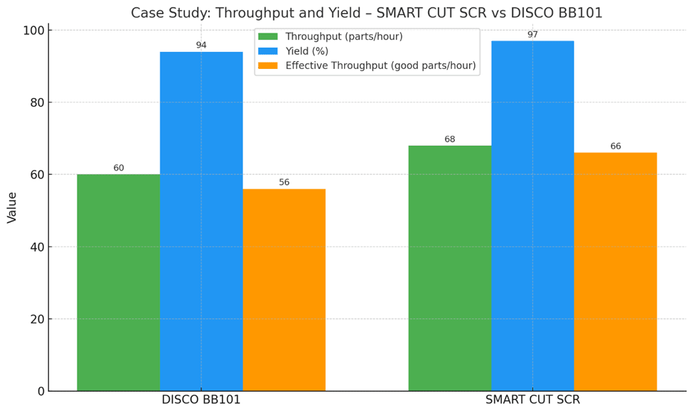
Conclusion
The SMART CUT® SCR resin bond blade delivered both higher throughput and higher yield compared to DISCO BB101 in borosilicate glass cutting. By enabling faster cutting speeds and producing more usable parts, SCR blades reduce cost per part and increase production efficiency.
Downtime
Downtime is the period of lost production caused by blade changes, dressing, or machine recalibration. Every time a diamond dicing blade reaches the end of its life or requires adjustment, the saw must be stopped. This interruption reduces productivity, delays output, and increases labor costs. Frequent downtime also disrupts workflow planning, since operators need to dedicate additional time to maintenance rather than active production.
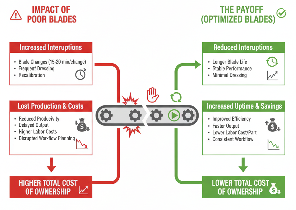
The impact of downtime becomes greater in high-volume environments where even small interruptions compound into significant losses. For example, if a blade with short life requires multiple replacements in a single shift, the accumulated downtime can exceed the cutting time itself. Choosing blades with longer life, stable performance, and minimal dressing requirements reduces the number of interruptions. This not only improves efficiency but also lowers the cost per part by ensuring machines stay operational for longer periods.
Coolant and Dressing Requirements
Coolant and dressing requirements represent an often-overlooked part of the total cost of operating diamond dicing blades. These costs are tied directly to maintaining consistent blade performance throughout production.

Coolant is essential for keeping the blade and material cool during cutting, flushing debris from the kerf, and reducing friction. Insufficient or poor-quality coolant can cause overheating, accelerated wear, and excessive chipping. At the same time, overuse of coolant increases operating costs. Finding the correct balance helps extend blade life and ensures cleaner, more accurate cuts.
Dressing is another important maintenance factor. Over time, diamond dicing blades can become glazed as the bond material dulls or loads with debris. Dressing exposes fresh diamond particles, restoring cutting efficiency. However, frequent dressing interrupts production and adds labor costs. Blades that maintain sharpness longer and require less dressing reduce downtime and improve productivity.
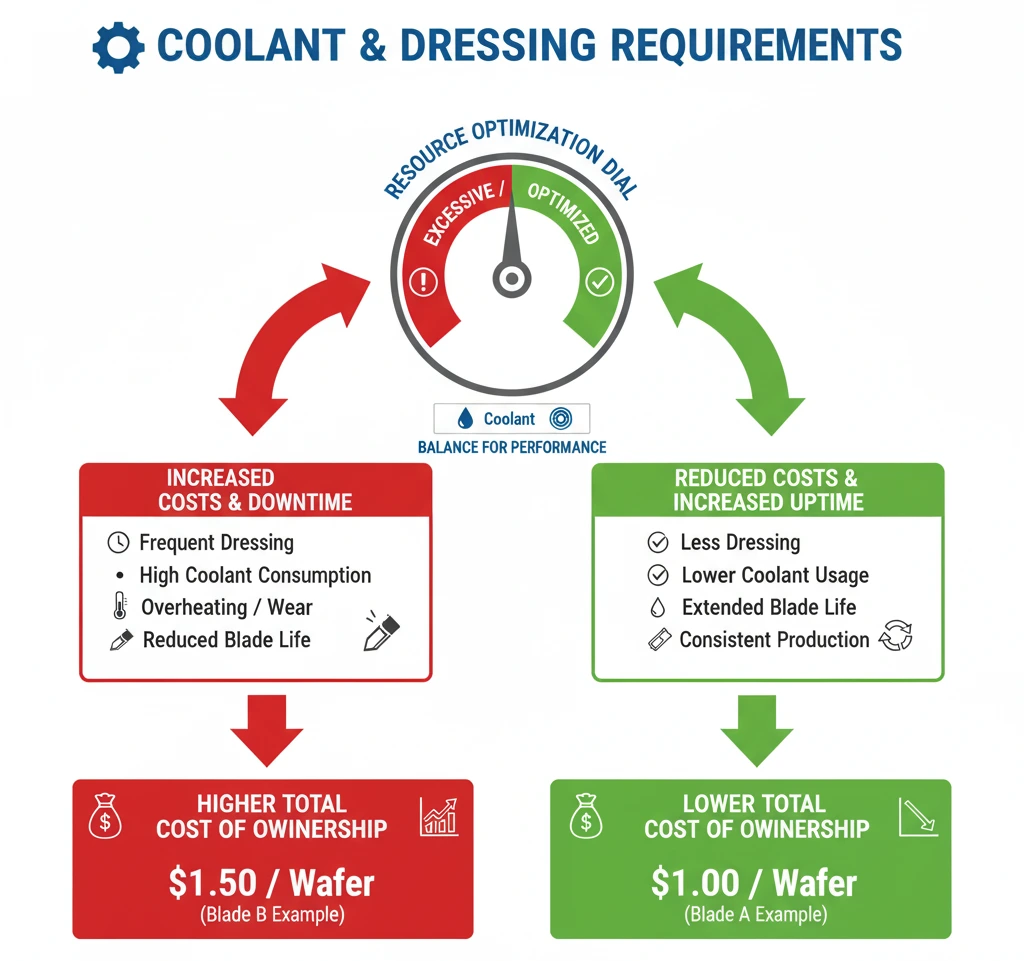
When evaluating the total cost of cutting, coolant consumption and dressing frequency must be included alongside blade life and yield. A blade that requires less coolant and fewer dressing cycles may have a higher purchase price but will lower the overall cost of ownership by reducing consumable usage, labor, and lost machine time.
Example
- Blade A costs $500 and cuts 500 wafers before replacement → $1 per wafer.
- Blade B costs $300 but only cuts 200 wafers before replacement → $1.50 per wafer.
Even though Blade B has a lower price, Blade A is more cost-effective because of longer life and lower cost per part.
When evaluating dicing blade economics, many buyers look only at purchase price or blade life. In practice, indirect costs can account for 20–40 percent of total cutting expense. A blade that minimizes equipment wear, reduces maintenance and labor, and consumes less energy often delivers the lowest true cost of ownership, even if its upfront price is slightly higher.
Equipment Depreciation
Equipment depreciation is a significant but indirect cost of wafer dicing. Every cut contributes to wear on the machine’s most critical systems, including the spindle, linear guides, flanges, and precision alignment assemblies. Over time, this reduces accuracy, increases vibration, and raises the likelihood of mechanical failure.
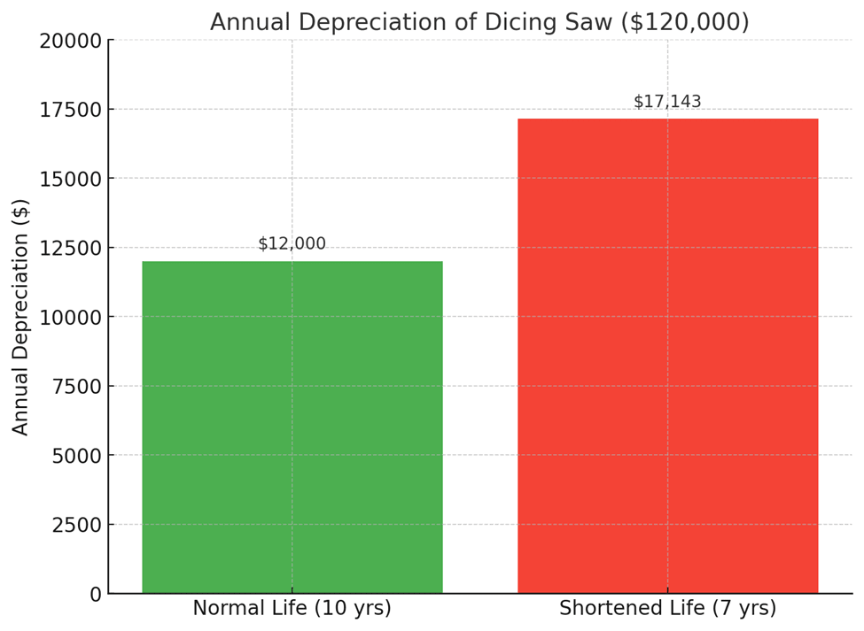
With new dicing machines costing $100,000 to $150,000, the financial impact of accelerated wear is substantial. If a $120,000 dicing saw is depreciated over 10 years, that equals $12,000 per year in depreciation. However, if poor blade selection or unstable cutting shortens the machine’s life to 7 years, annual depreciation effectively rises to $17,100 per year. That hidden increase of over $5,000 per year can outweigh any perceived savings from using cheaper or less suitable blades.
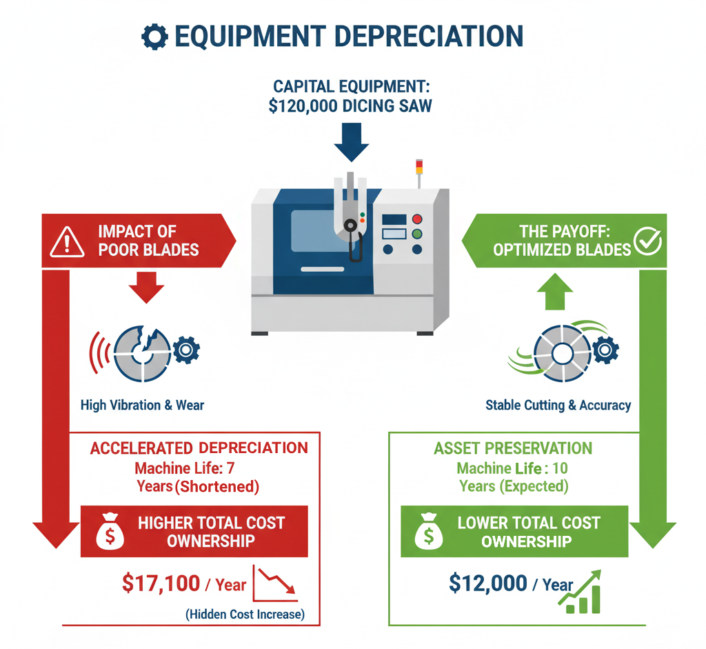
Blades that generate high cutting forces, excessive vibration, or inconsistent kerf widths put added stress on the spindle and flanges. This accelerates wear, forces more frequent maintenance, and shortens the useful life of the machine. By contrast, a stable and well-matched blade cuts smoothly, minimizes vibration, and preserves spindle accuracy, extending the equipment’s service life and lowering total cost of ownership.
The choice of dicing blade should therefore be viewed not only in terms of yield and blade life but also as a protective measure for capital equipment. A premium blade that maintains stable performance may add a few dollars to blade cost but can save tens of thousands of dollars in machine depreciation and unplanned downtime over the life of the saw.
Here is a chart showing the impact of equipment depreciation on a $120,000 dicing saw. It compares annual depreciation when the machine lasts its expected 10 years versus when its life is shortened to 7 years due to poor blade performance.
Maintenance
Maintenance is a critical factor in the long-term cost of ownership of dicing operations. Dicing saws are precision machines, and their performance depends on maintaining tight tolerances in every component. Regular calibration, flange inspection, spindle balancing, and coolant system cleaning are essential tasks to ensure accuracy, minimize vibration, and preserve cut quality.
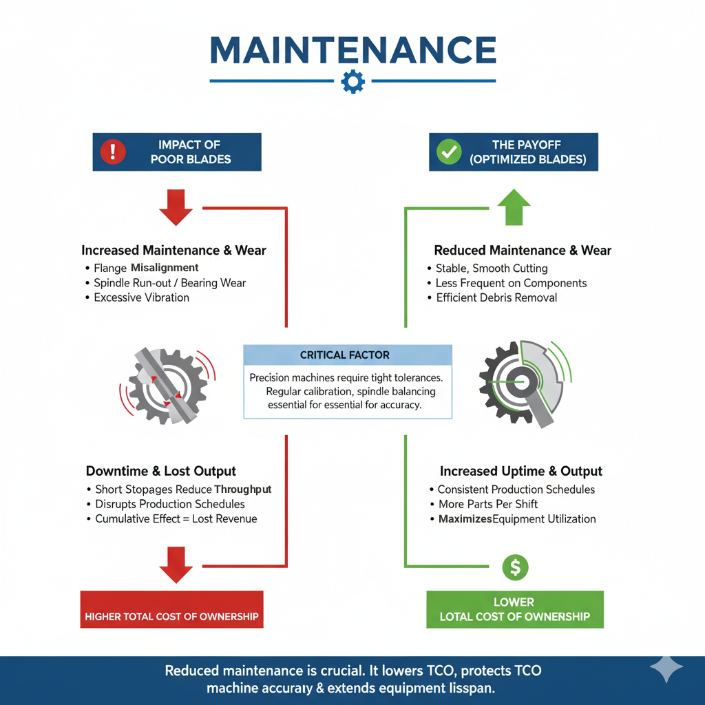
Poor blade performance directly increases the need for maintenance. A blade that generates excess vibration or uneven cutting pressure can cause flange misalignment, spindle run-out, and bearing wear. Likewise, a blade that produces excessive debris or requires frequent dressing puts additional load on the coolant and filtration systems, forcing more frequent cleanings. Over time, these problems accumulate, leading to higher maintenance costs and reduced machine life.
Every maintenance intervention also means downtime. Even short stoppages for re-alignment, cleaning, or dressing reduce throughput and disrupt production schedules. In high-volume environments, the cumulative effect of repeated interruptions can represent thousands of dollars in lost output each year.
By contrast, a stable, well-matched dicing blade that cuts smoothly and stays sharp for longer intervals reduces maintenance requirements significantly. Less frequent dressing means cleaner cuts and fewer interruptions. Stable cutting pressure minimizes wear on spindles and flanges, keeping the machine in calibration for longer periods. Efficient debris removal reduces strain on the coolant system, extending the life of filters and pumps.
When viewed in the context of total cost of ownership, reduced maintenance is just as important as blade life. A blade that lowers maintenance demands not only cuts more efficiently but also preserves machine accuracy, reduces downtime, and extends the lifespan of costly components. In the long run, this can provide greater savings than the difference in blade purchase price.
Labor
Labor is one of the most underestimated indirect costs in dicing operations. Even though blades are consumables, the time and attention required from skilled operators often outweigh the blade’s purchase price. Operators must perform setup, alignment, monitoring, blade changes, dressing, and troubleshooting, and each of these tasks consumes time that could otherwise be spent on higher-value activities.
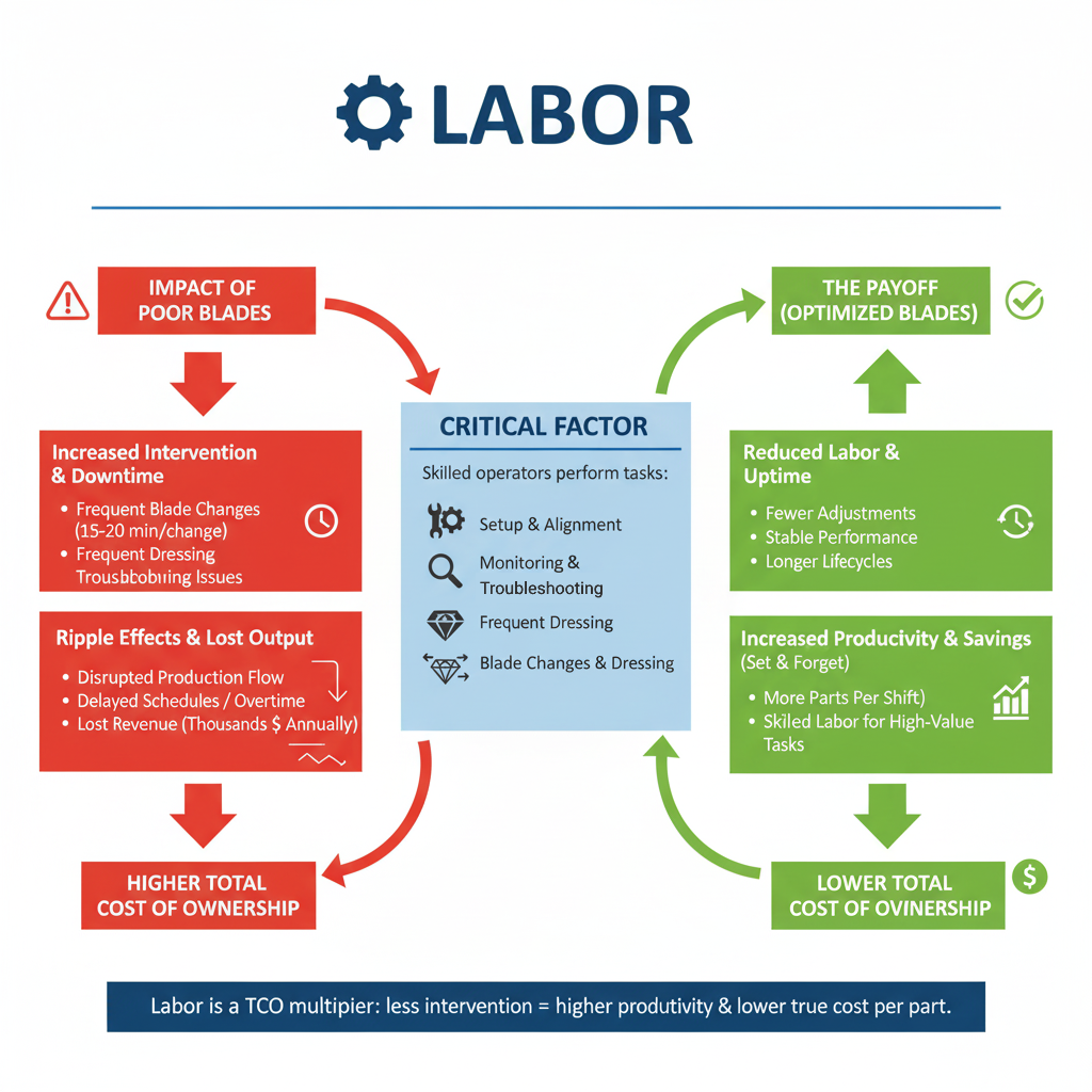
Frequent blade replacement or dressing magnifies this issue. For example, if a blade needs to be changed multiple times per shift, each change may require 15 to 20 minutes of machine stoppage and operator intervention. Across a month of production, this can add up to several hours of downtime and hundreds of dollars in labor costs. A blade that requires fewer adjustments and maintains stability throughout its life cycle reduces these interruptions.
The ripple effects of labor cost go beyond direct wages. Frequent downtime disrupts production flow, delays delivery schedules, and increases the need for overtime. In high volume environments, even a 10–15 minute reduction in downtime per shift translates into thousands of dollars saved annually. This is why a blade that lasts longer and cuts consistently is more valuable than a cheaper blade that forces frequent operator involvement.
From a cost-of-ownership perspective, labor is not just an indirect expense it is a multiplier. The more often operators have to intervene, the less productive the entire line becomes. Blades that enable operators to “set and forget” improve throughput, free skilled labor for more advanced tasks, and ultimately lower the real cost per wafer or per part.
Energy Consumption
Energy consumption is another hidden cost that directly links to dicing blade performance. Dicing equipment operates continuously, with spindles, coolant pumps, and vacuum systems running throughout each cut. The efficiency of the blade determines how much power the machine needs to maintain cutting speed and quality.
Blades with poor cutting efficiency generate more friction and resistance during operation. This forces the spindle motor to work harder, drawing more current and producing excess heat. Higher friction also means more cooling power is required to prevent thermal damage, increasing the load on pumps and coolant circulation systems. Together, these factors elevate energy consumption and raise the cost per cut.
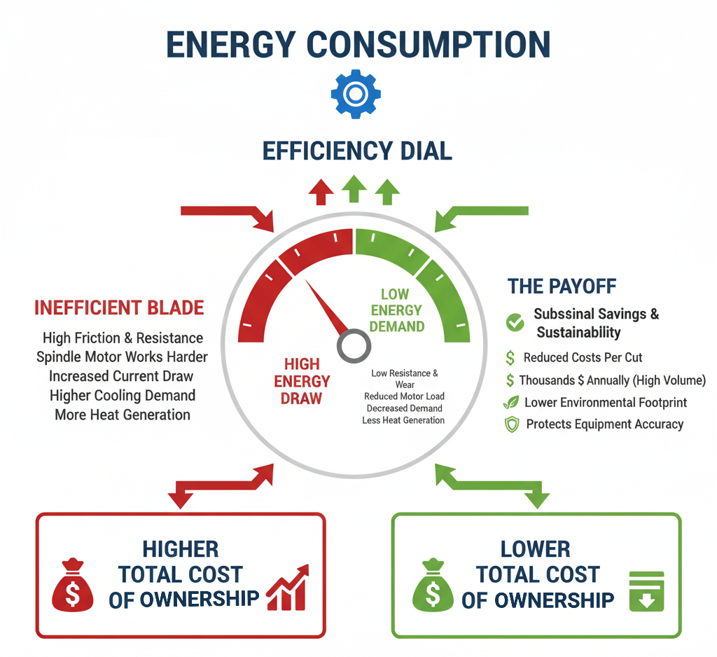
By contrast, a blade that is engineered for optimal sharpness, grit size, bond type, and cutting speed slices through material with less resistance. This reduces spindle torque requirements, lowers motor load, and decreases coolant demand. The result is a measurable reduction in energy use per wafer or per part. Over thousands of wafers, this translates into substantial cost savings and less wear on support equipment.
Beyond cost, energy efficiency has sustainability benefits. Lower energy demand reduces the environmental footprint of the dicing process, an increasingly important factor for manufacturers working under green compliance requirements or with clients prioritizing environmentally responsible supply chains.
In practice, the difference between an inefficient blade and a well-optimized blade may only be a few cents per wafer in energy cost. But across continuous high-volume operations, these cents add up to thousands of dollars annually. More importantly, reduced energy demand lowers heat generation, which in turn protects spindle accuracy, reduces vibration, and extends the life of both the blade and the machine.
Need Help Selecting the Right Diamond
or CBN Tool for Your Application?
Our applications engineers will review your material, machine, and cutting parameters and recommend the optimal
Diamond or CBN Tool specification/solution for your application
Free consultation. No obligation.
Trusted by Tens of Thousands of Manufacturers, Laboratories,
Research Institutions Worldwide Since 1990

American Based Manufacturer

Established in 1990


Custom manufacturing


ARE YOU USING RIGHT TOOLS
FOR YOUR APPLICATION?
LET US
HELP YOU
HAVING ISSUES WITH
YOUR CURRENT TOOLS?
Knowledge Center

Optimizing QFN Package Dicing Process Using SMART CUT® Dicing Blades

Select right Diamond Dicing Blade for your application
Dicing Blade Operations Recommendations
Optimizing your Diamond Dicing Performance
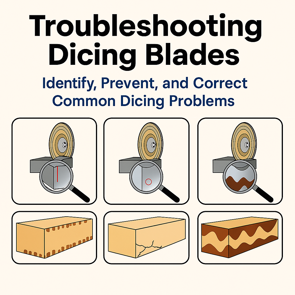
Trouble Shooting Dicing Problems

Application Recommendations
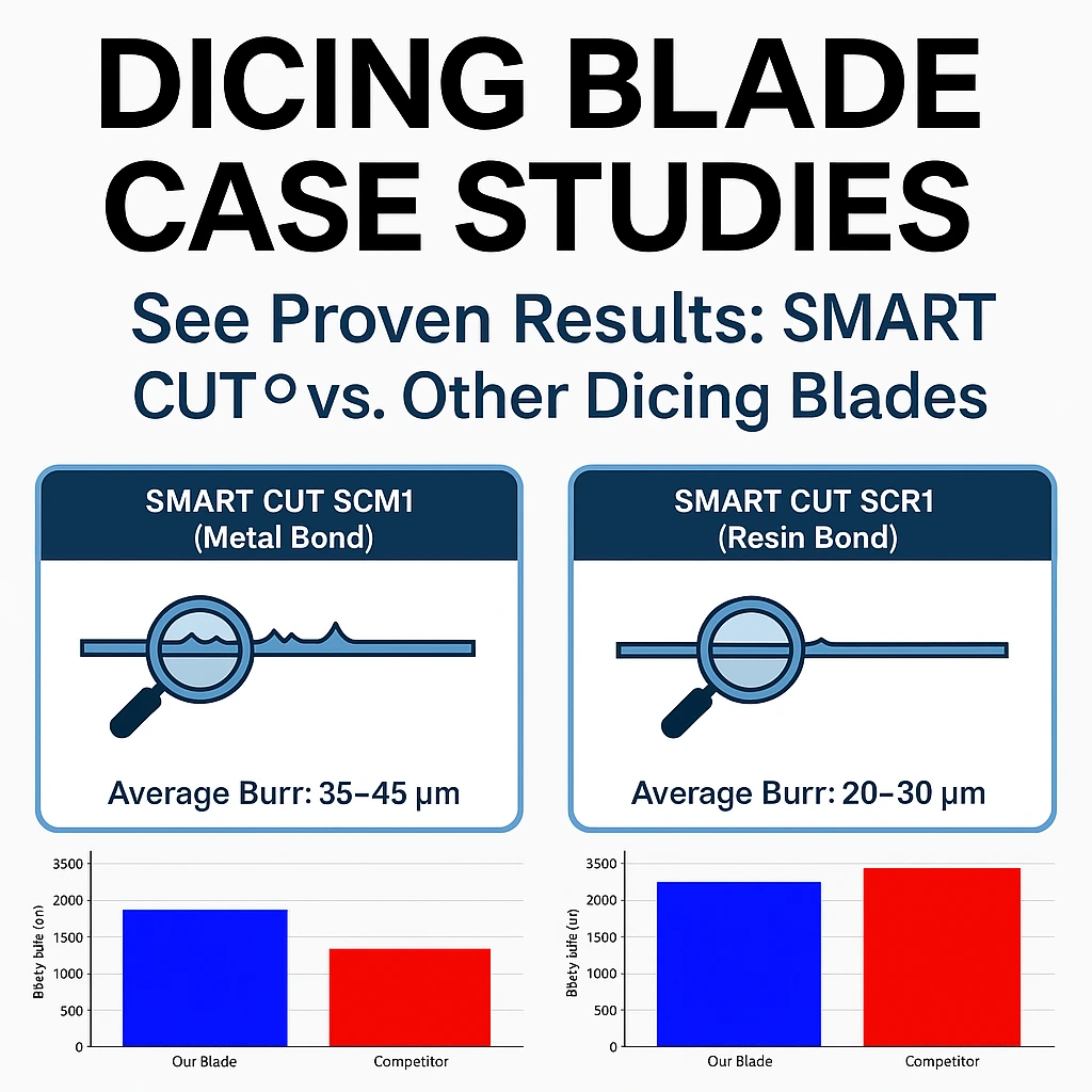
Dicing Blade Case Studies
Selecting the Right Wafer Dicing Saw Practical Guide

Total Cost of Ownership – Measuring the Real Economics of Diamond Dicing
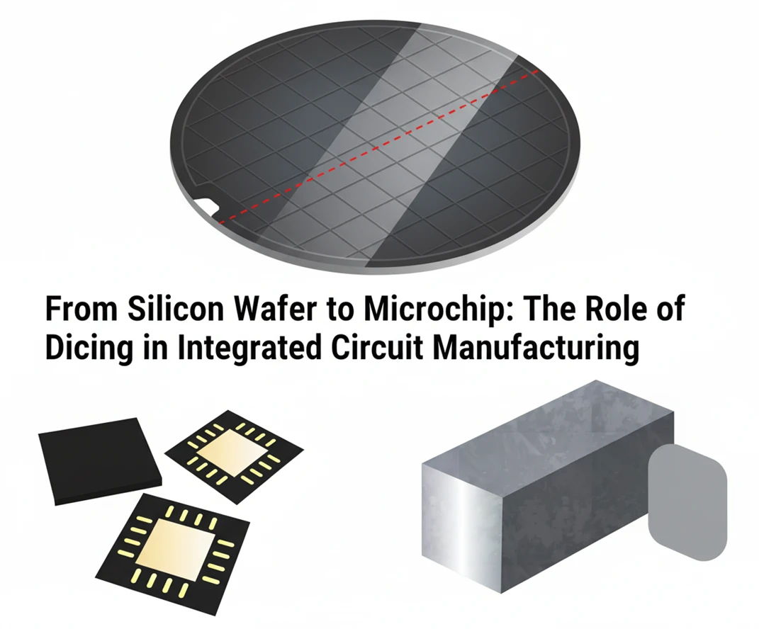
From Silicon Wafer to Microchip: The Role of Dicing in Integrated Circuit Manufacturing
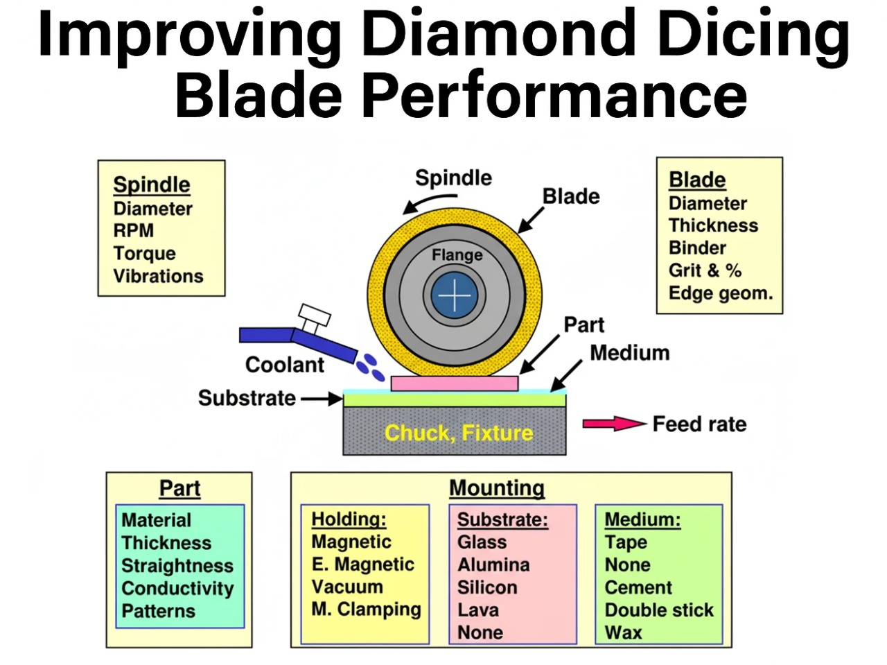
Improving Diamond Dicing Blade Performance: Key Factors and Strategies
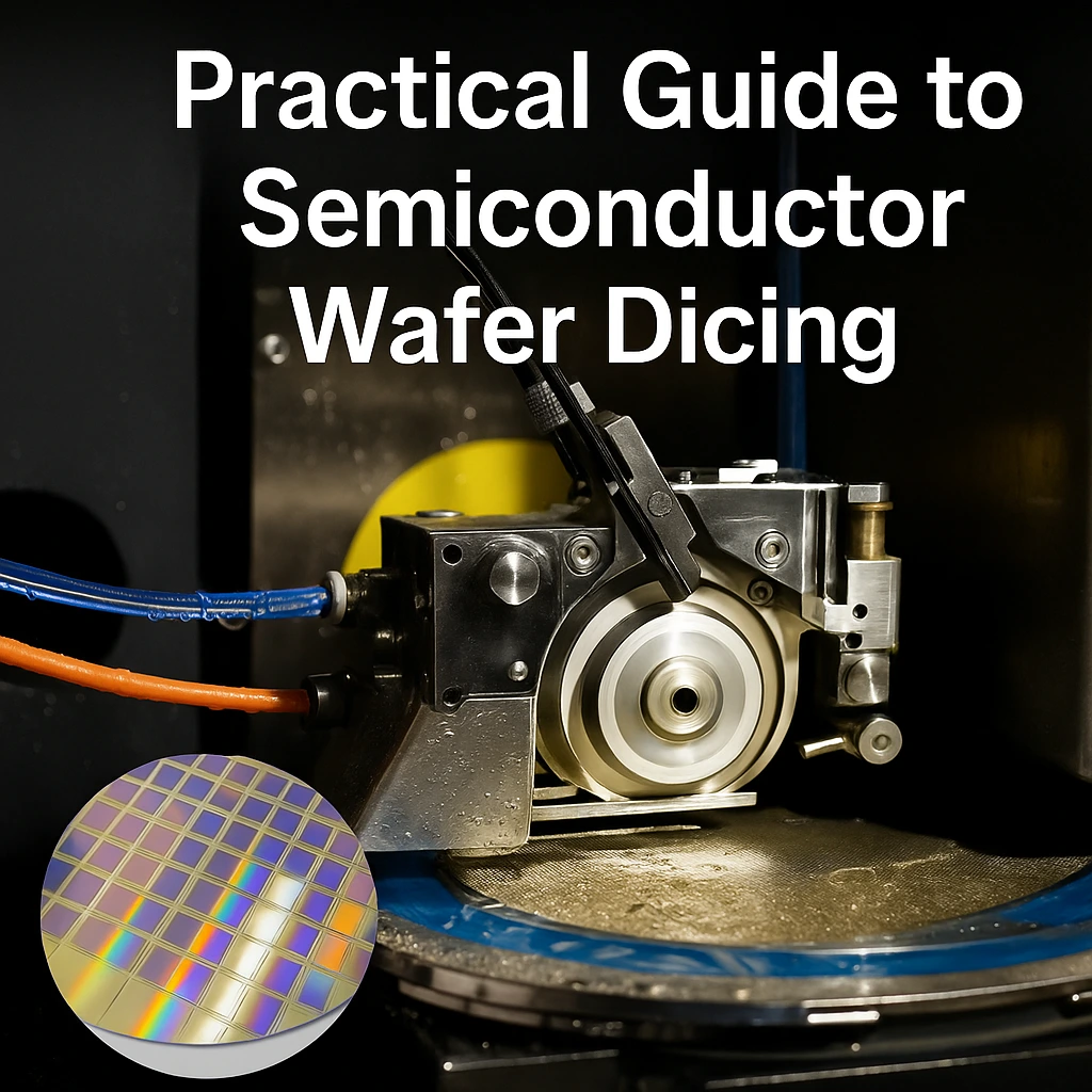
Practical Guide to Semiconductor Wafer Dicing: Materials, Blades, and Process Optimization
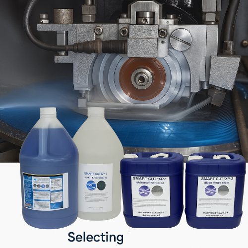
Selecting the Right Dicing Surfactant / Fluid for Your Application
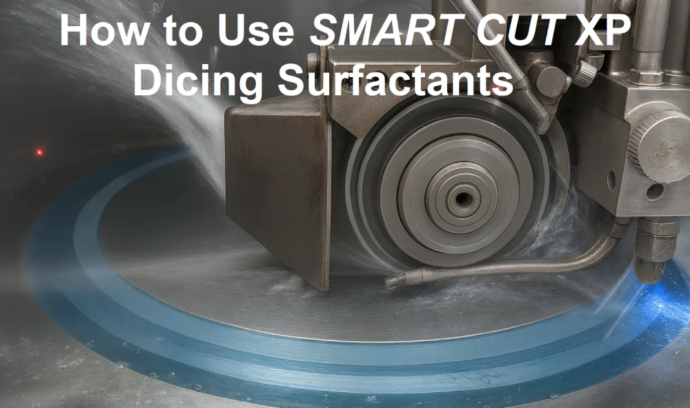
How to Use SMART CUT XP Dicing Surfactants