


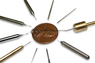
Micro Drilling Guide


-
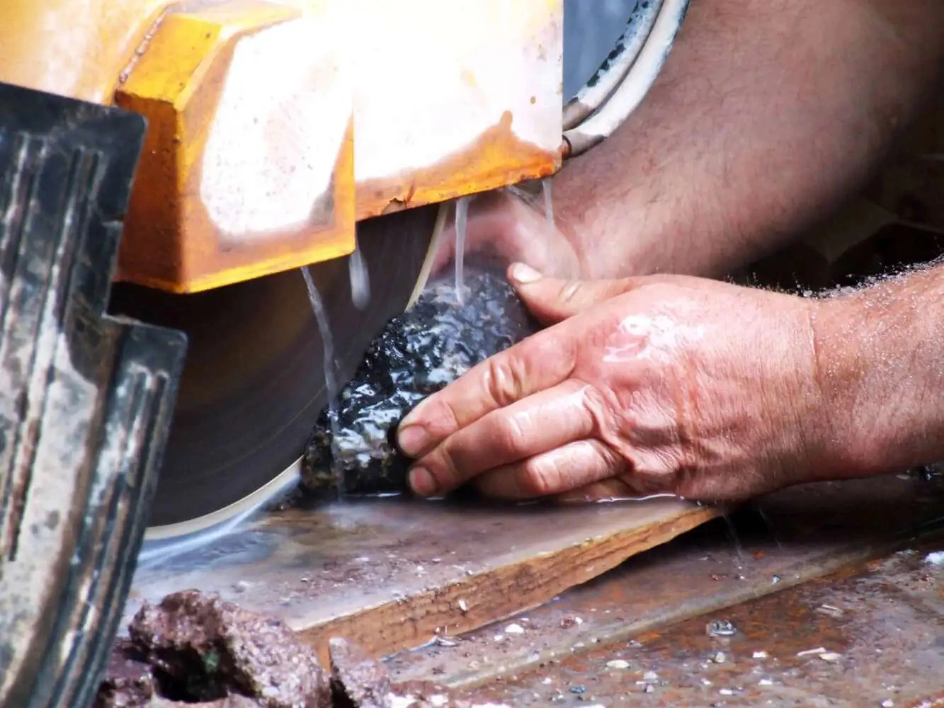
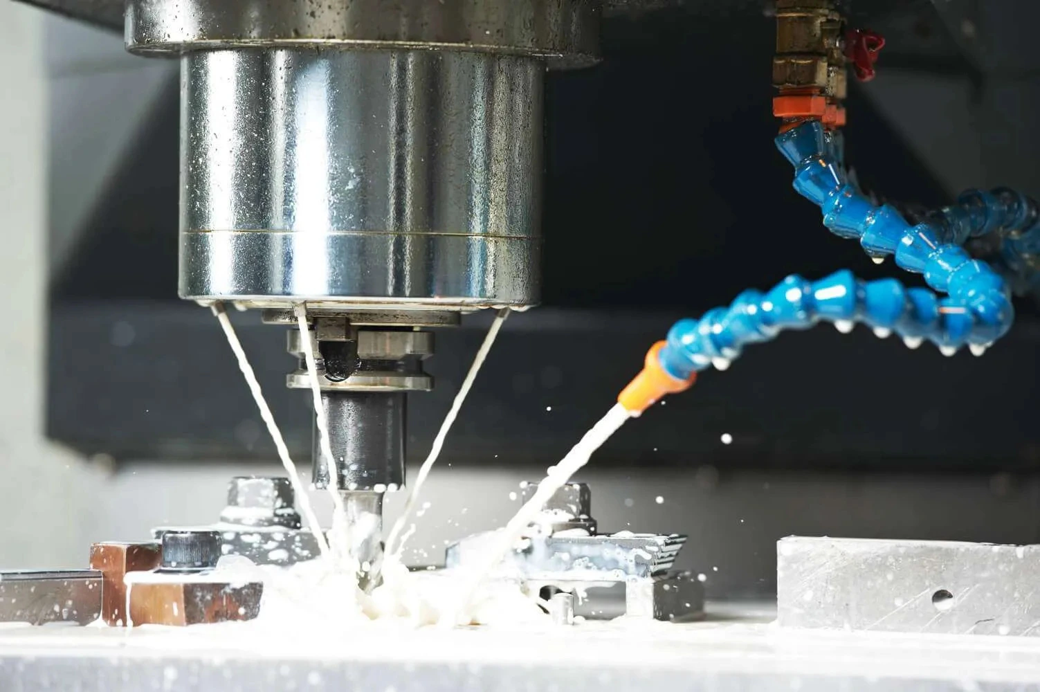
 Cools drill diamond section and material being drilled
-
Provides lubrication to minimize friction between drill and material
-
Washes out and removes powder residue and swarf from drilling process
-
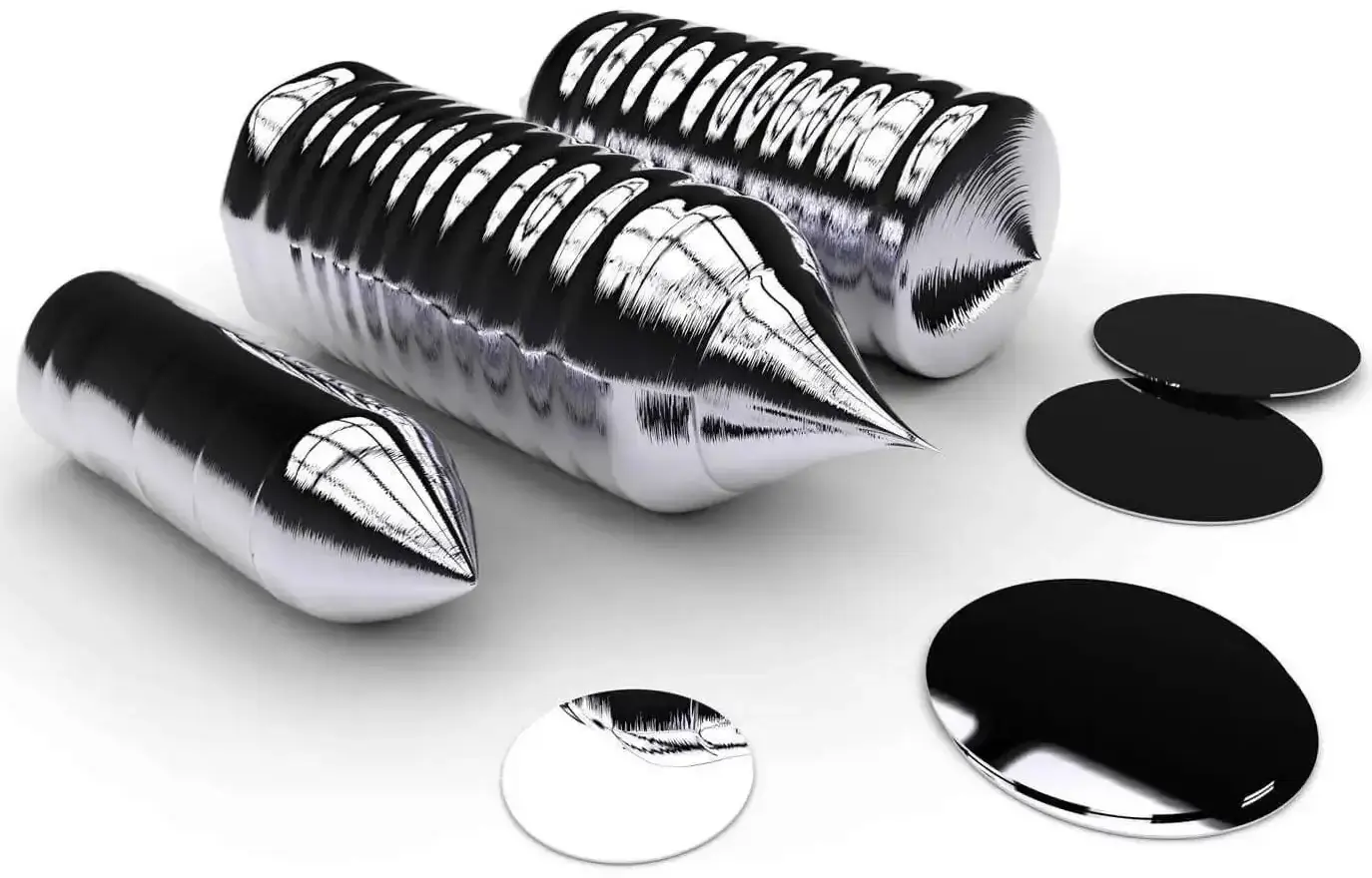
Improved holding characteristics, specially when drilling thin material substrates/wafers
-
No lip effect – capability to drill much deeper into the base material. This typically results in better surface finish quality, specially on backside of material.
-
Substrates not perfectly flat can be mounted. The wax/glue compensates by filling in the gaps
-
Different hardness base media can be used to control drill wear and simultaneously dress the drill. Common base media used is glass or ceramic.
-
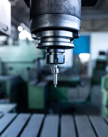
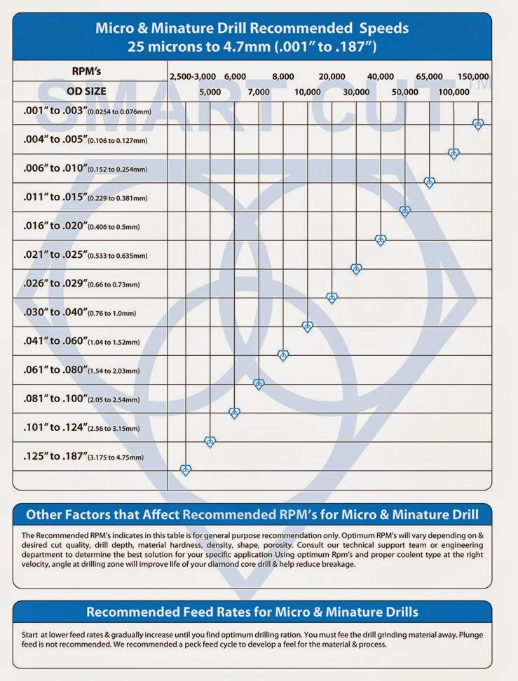
Spindle speed
-
Spindle collet run-out
-
Pressure foot
-
Axes positioning and stability

Ayan Sadyk is a materials scientist and process engineer with over two decades of experience in the industrial diamond tooling sector. His expertise lies in integrating ultra-thin diamond blades, CBN wheels, and advanced cutting systems into precision manufacturing workflows for applications in optics, semiconductors, and technical ceramics.
With a background in materials behavior and surface integrity, Mr. Sadyk brings a data-driven, application-specific approach to cutting and grinding process development. He has worked closely with manufacturers and R&D facilities across Eastern Europe, North America, and the Middle East, helping optimize tool life, surface finish, and process stability.
As an author, he focuses on bridging materials science with tooling innovation—writing on topics such as blade wear mechanisms, thermal effects in hard material sectioning, and adaptive process design.
Select Right Diamond Drill for your Application

How to Properly Use Precision Diamond Drills
Diamond Core Drills: Materials, Applications & Selection Guide

Diamond Tools Guide – Selecting Right Drills & Tools for your application

Optimizing your Diamond Drilling Operation
Micro Drilling Guide

Selecting Right Drilling Equipment for your Application. What you features & functionality you should look for?
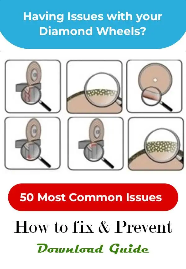
Diamond Core Drill & Drill Trouble Shooting Guide

Understanding & Calculating Return on Investment for Diamond Core Drills & Other Tools

Understanding Tradeoffs – Searching for Perfect Diamond Drill & Tool

Why Use Diamond Drills?
Ayan Sadyk is a materials scientist and process engineer with over two decades of experience in the industrial diamond tooling sector. His expertise lies in integrating ultra-thin diamond blades, CBN wheels, and advanced cutting systems into precision manufacturing workflows for applications in optics, semiconductors, and technical ceramics.
With a background in materials behavior and surface integrity, Mr. Sadyk brings a data-driven, application-specific approach to cutting and grinding process development. He has worked closely with manufacturers and R&D facilities across Eastern Europe, North America, and the Middle East, helping optimize tool life, surface finish, and process stability.
As an author, he focuses on bridging materials science with tooling innovation—writing on topics such as blade wear mechanisms, thermal effects in hard material sectioning, and adaptive process design.