


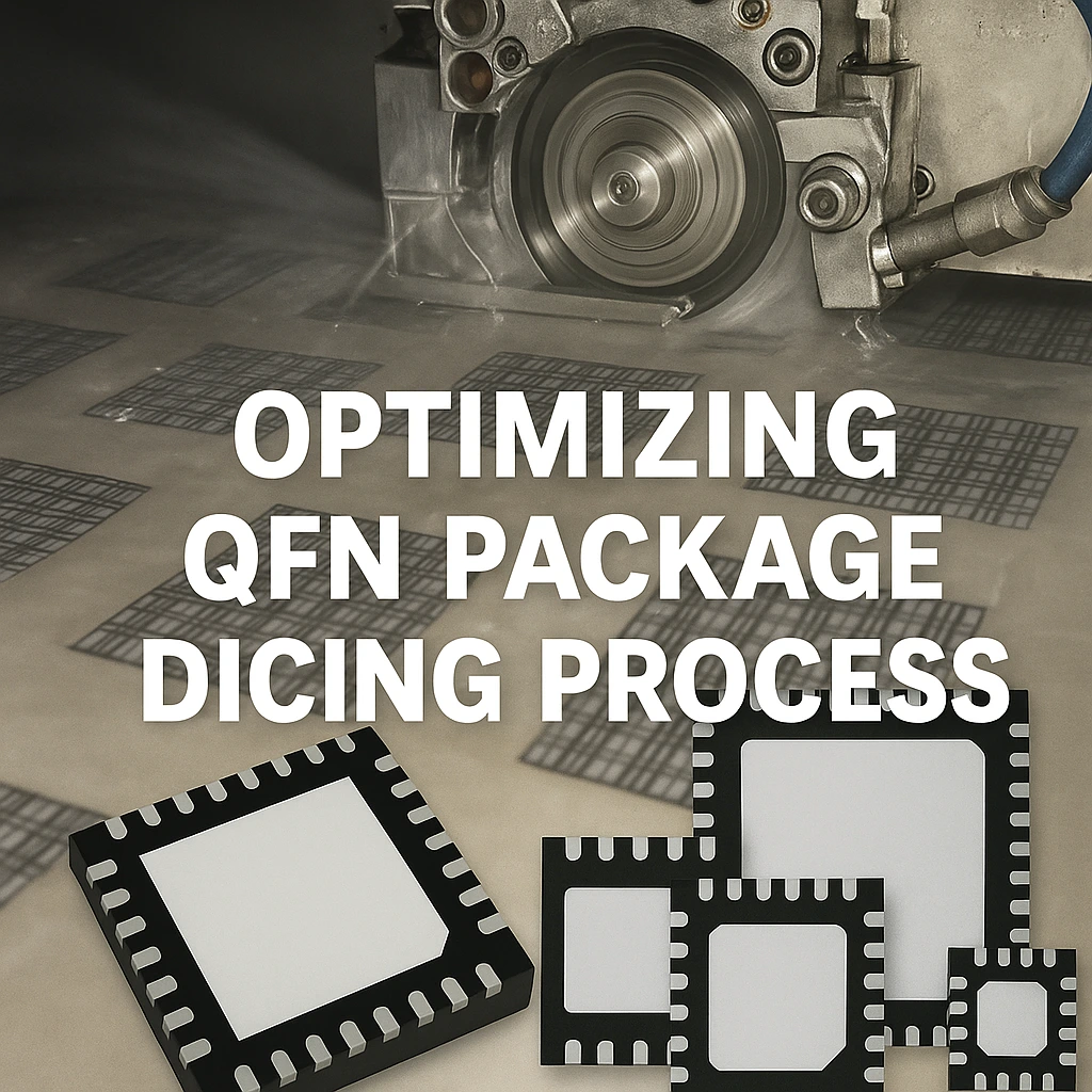
Optimizing QFN Package Dicing Process Using SMART CUT® Dicing Blades
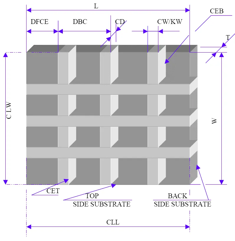
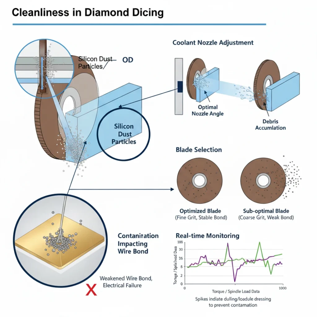
Dicing QFN packages presents several challenges due to the composition of materials and the precision required for clean, defect-free cuts. These challenges arise from the multi-layered structure of QFN packages, which often include tin (Sn) coatings, nickel/palladium (Ni/Pd) plating, and composite substrate materials. Each of these layers introduces specific difficulties that must be managed to ensure high-yield, high-quality production.

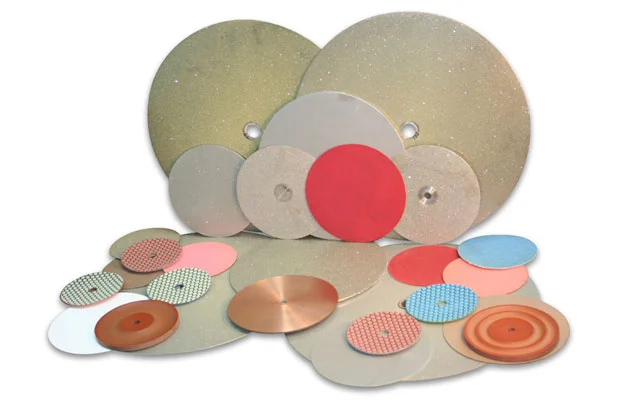
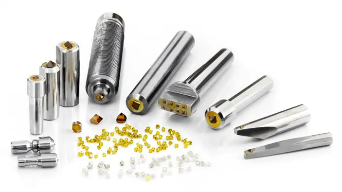
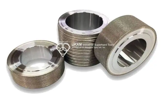
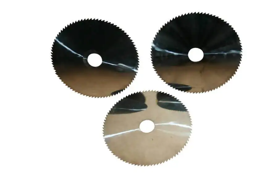
Select right Diamond Dicing Blade for your application
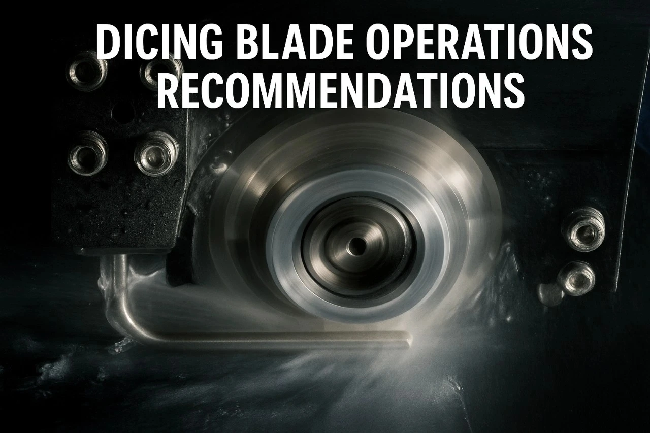
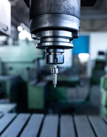
Dicing Blade Operations Recommendations
Selecting the right dicing blade parameters often involves a trial and error process, many aspects of which can be mitigated through experience and a deep understanding of how to optimize these parameters for specific applications. What works for one application may not work for another. While there is no true substitute for experience, even new dicing saw operators can quickly become proficient by learning and applying some basic principles of dicing. Much of the content in this guide has been published in industry magazines or presented at conventions.
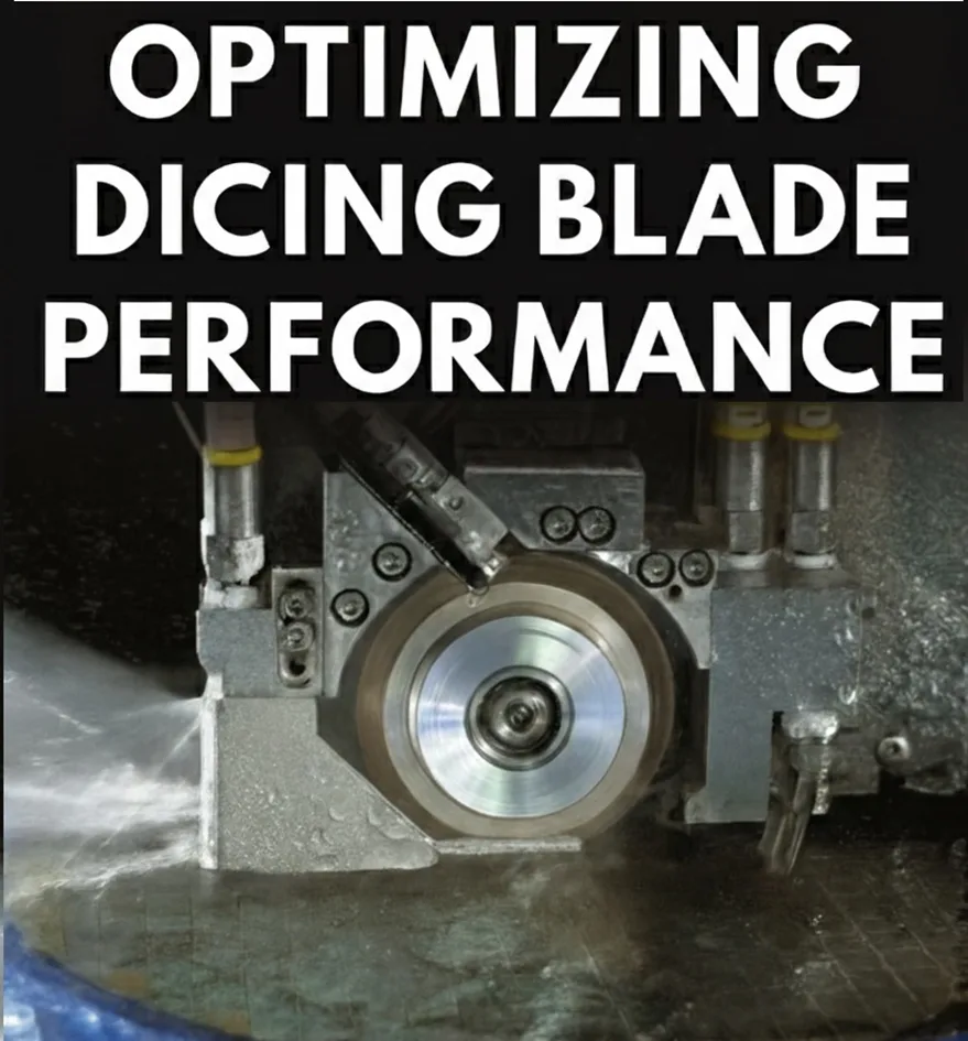
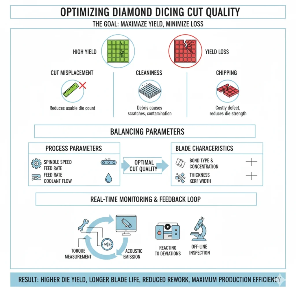
Optimizing your Diamond Dicing Performance
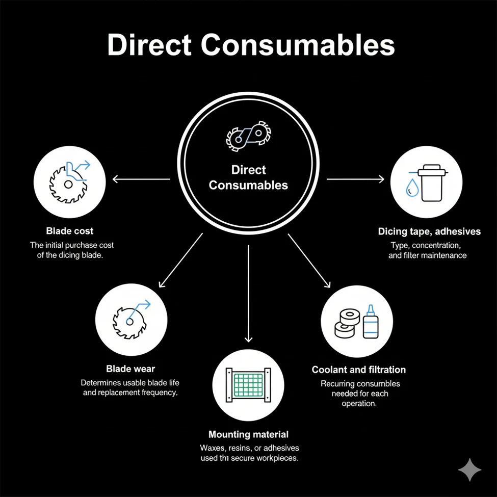
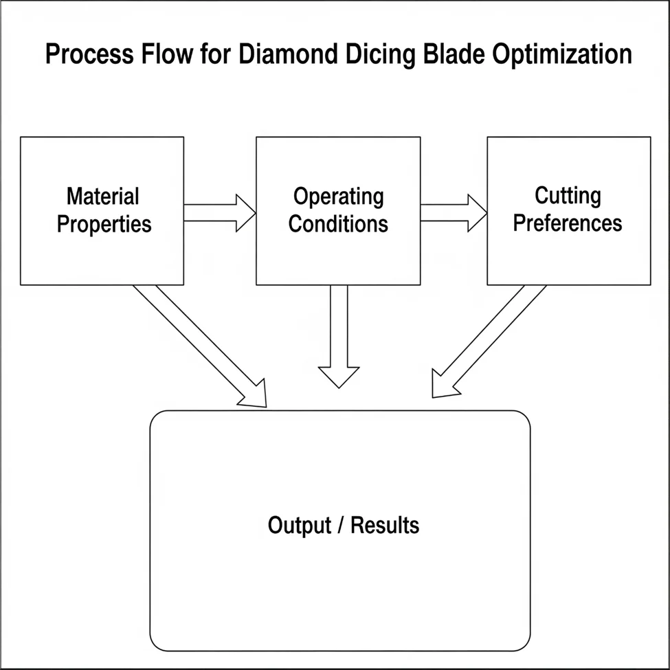
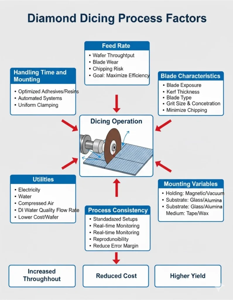
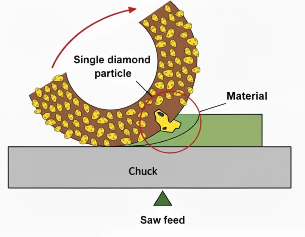
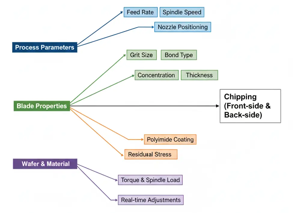
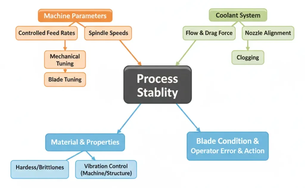
The performance of diamond dicing blades is influenced by a wide range of interdependent variables, and understanding these factors is essential for selecting the correct blade specifications and optimizing the dicing process. Each parameter, whether related to the blade itself, the material being cut, or the operating conditions, is only one part of a larger system. Adjusting a single factor in isolation rarely produces efficiency. True optimization comes only when all parameters are properly balanced and work together as a system.
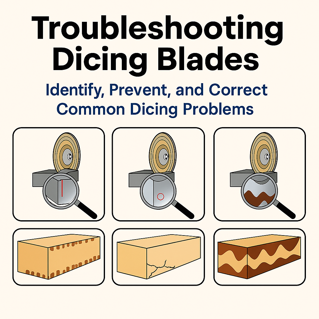
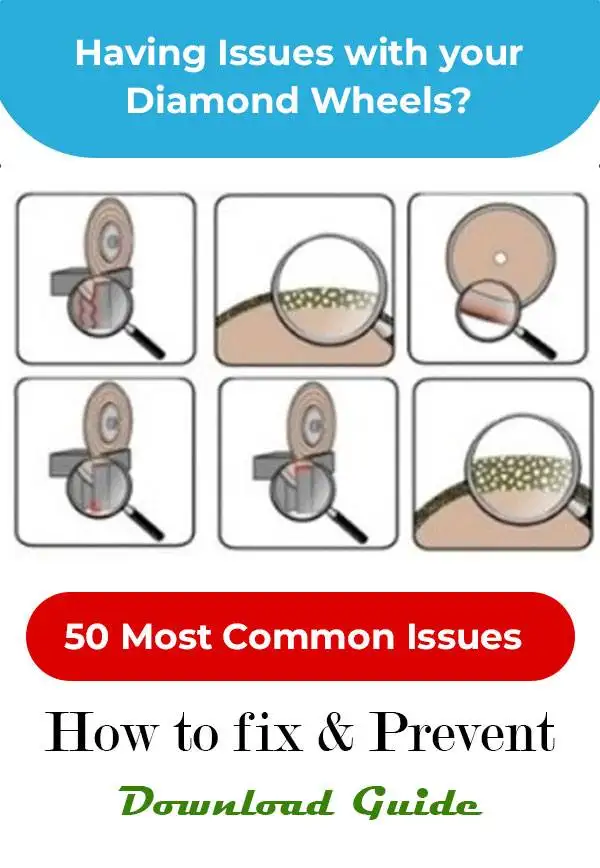
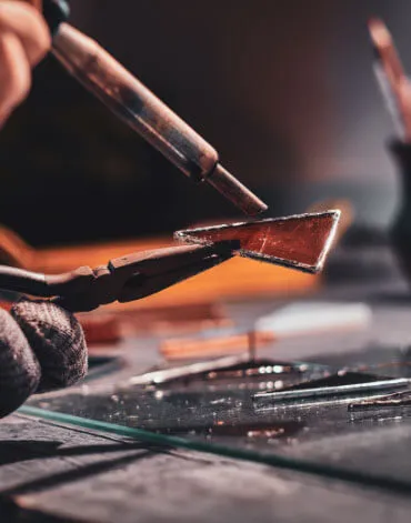
Trouble Shooting Dicing Problems
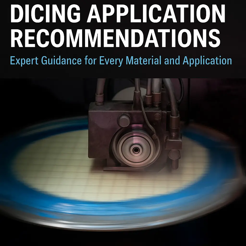
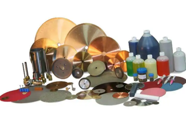
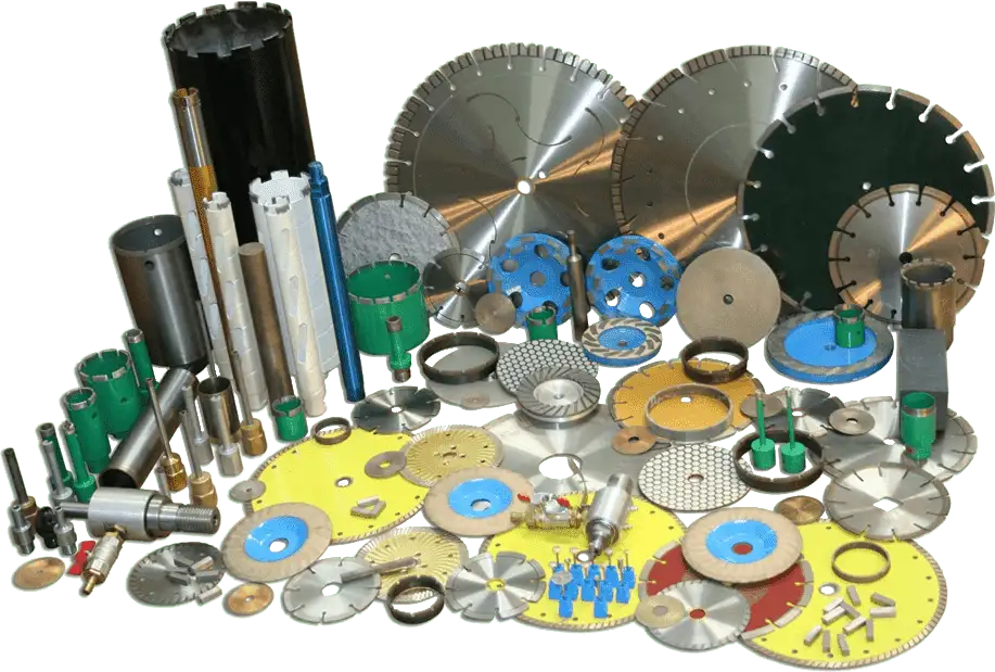
Application Recommendations
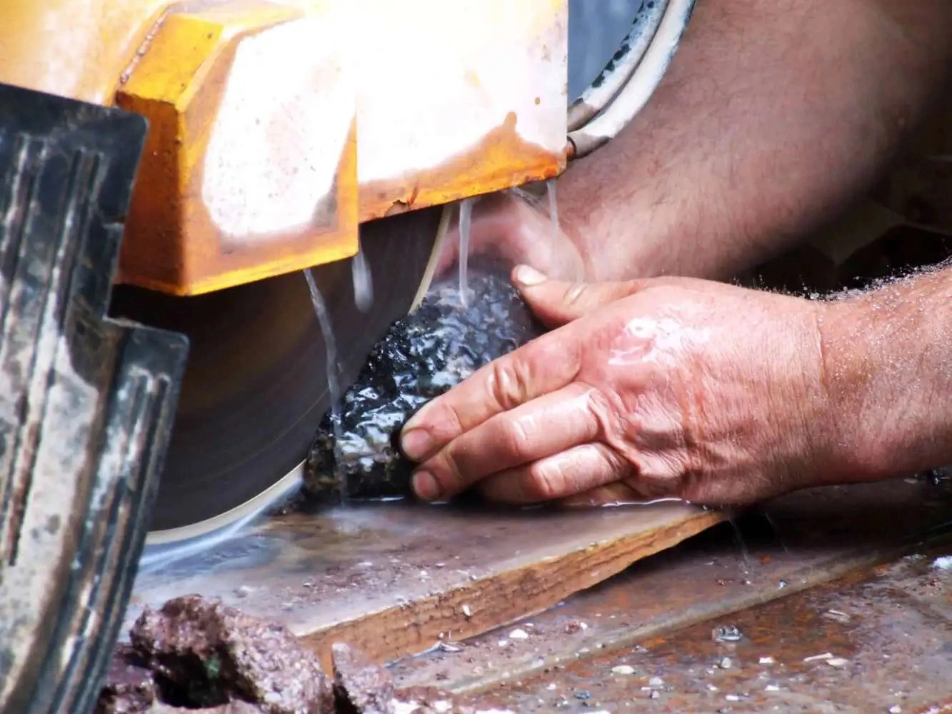
This article provides important guidelines for optimizing the dicing process in semiconductor packaging, focusing on package singulation for various technologies such as BGA, QFN, LED, CMOS, and wafer substrates. It covers key variables such as the recommended blade types, coolant options, RPMs, feed rates, and mounting methods to ensure high-quality results and efficient throughput. By exploring specific material requirements and common concerns, this guide offers valuable insights into selecting the ideal dicing parameters for each application.
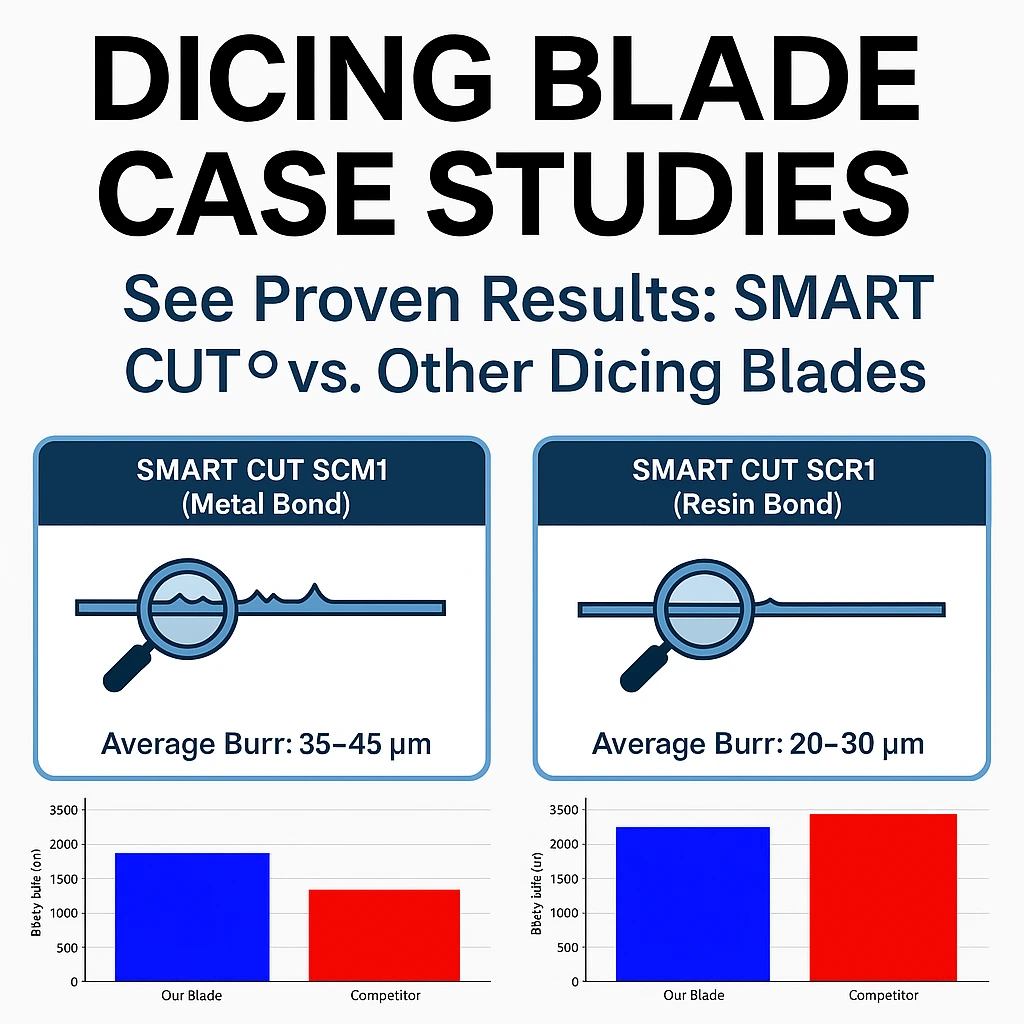
Dicing Blade Case Studies
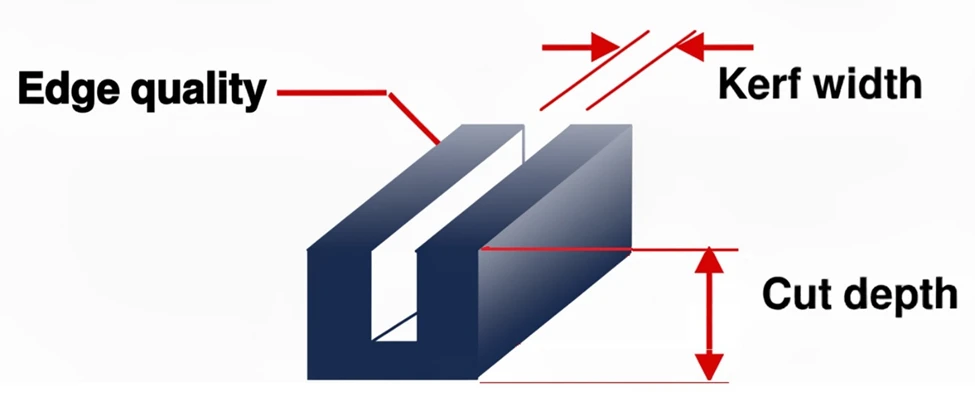
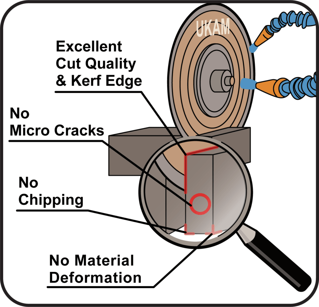
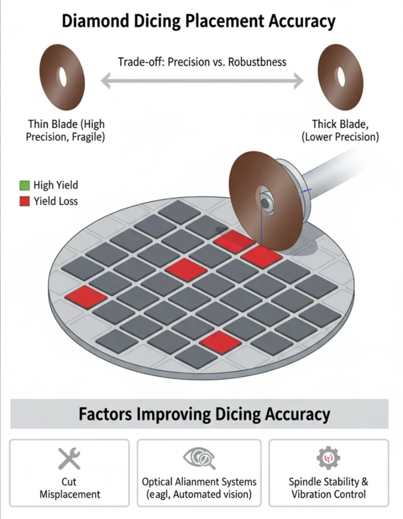
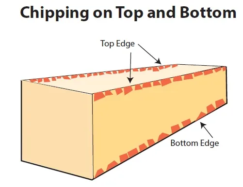
Selecting the right dicing blade is important to achieving high yields, superior edge quality, and consistent reliability in microelectronics and optics manufacturing. Across industries such as semiconductors, electronics packaging, photonics, and precision optics, even small improvements in blade performance can significantly reduce costs and improve output. Manufacturers often struggle with challenges like excessive chipping, burr formation, wafer damage, tool wear, and unstable cutting at higher feed rates.
Selecting the Right Wafer Dicing Saw Practical Guide

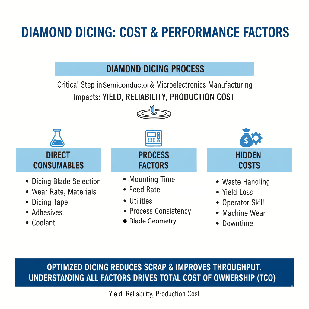
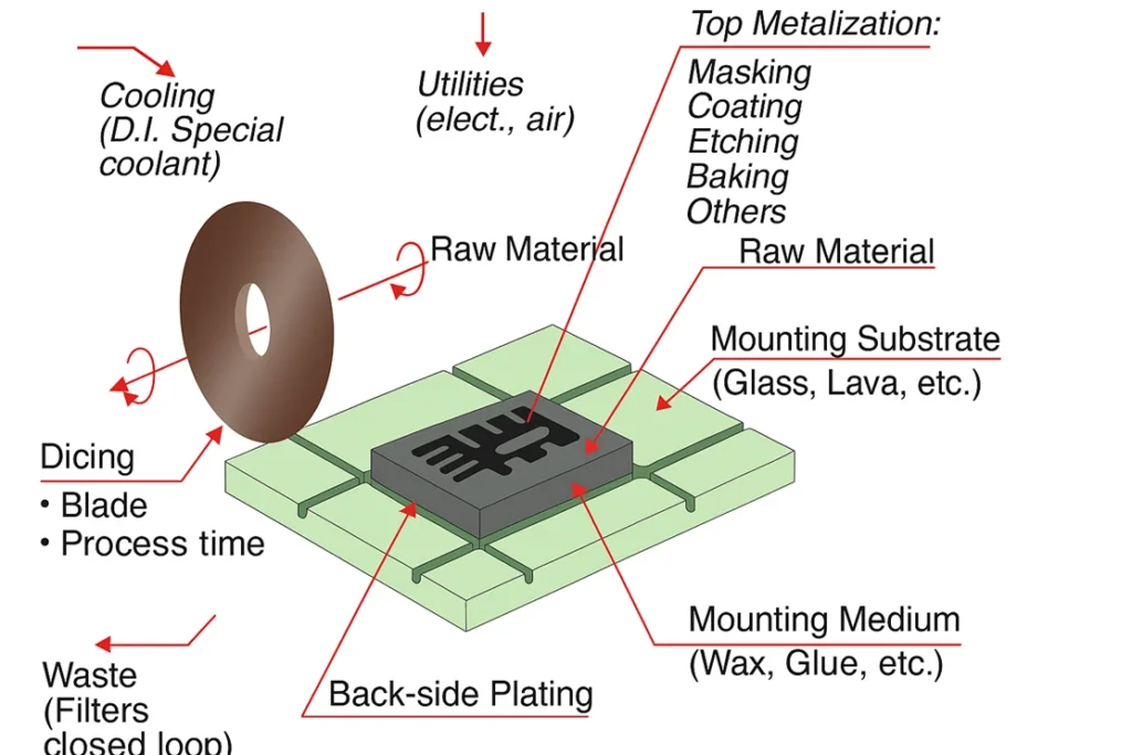
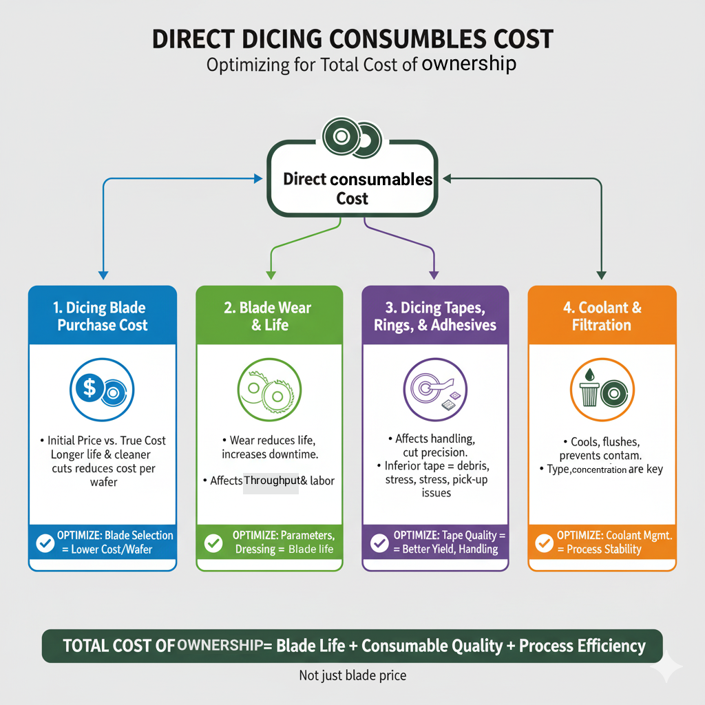
Total Cost of Ownership – Measuring the Real Economics of Diamond Dicing
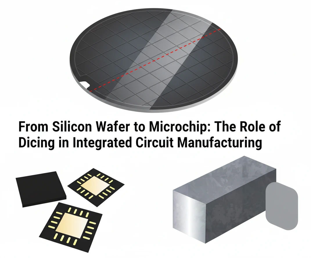
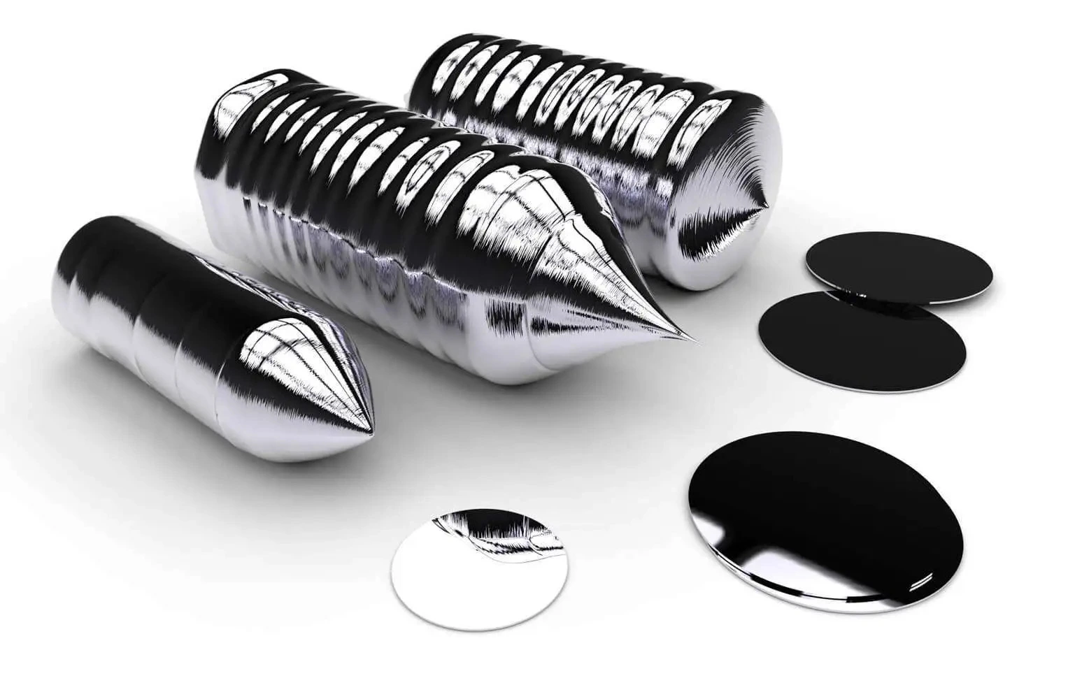
From Silicon Wafer to Microchip: The Role of Dicing in Integrated Circuit Manufacturing
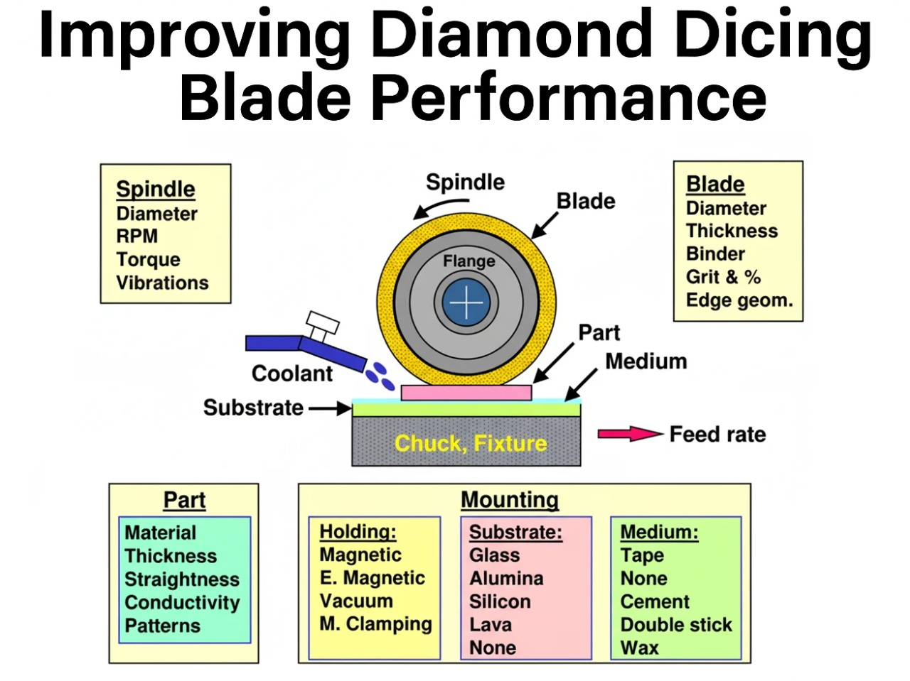
Improving Diamond Dicing Blade Performance: Key Factors and Strategies
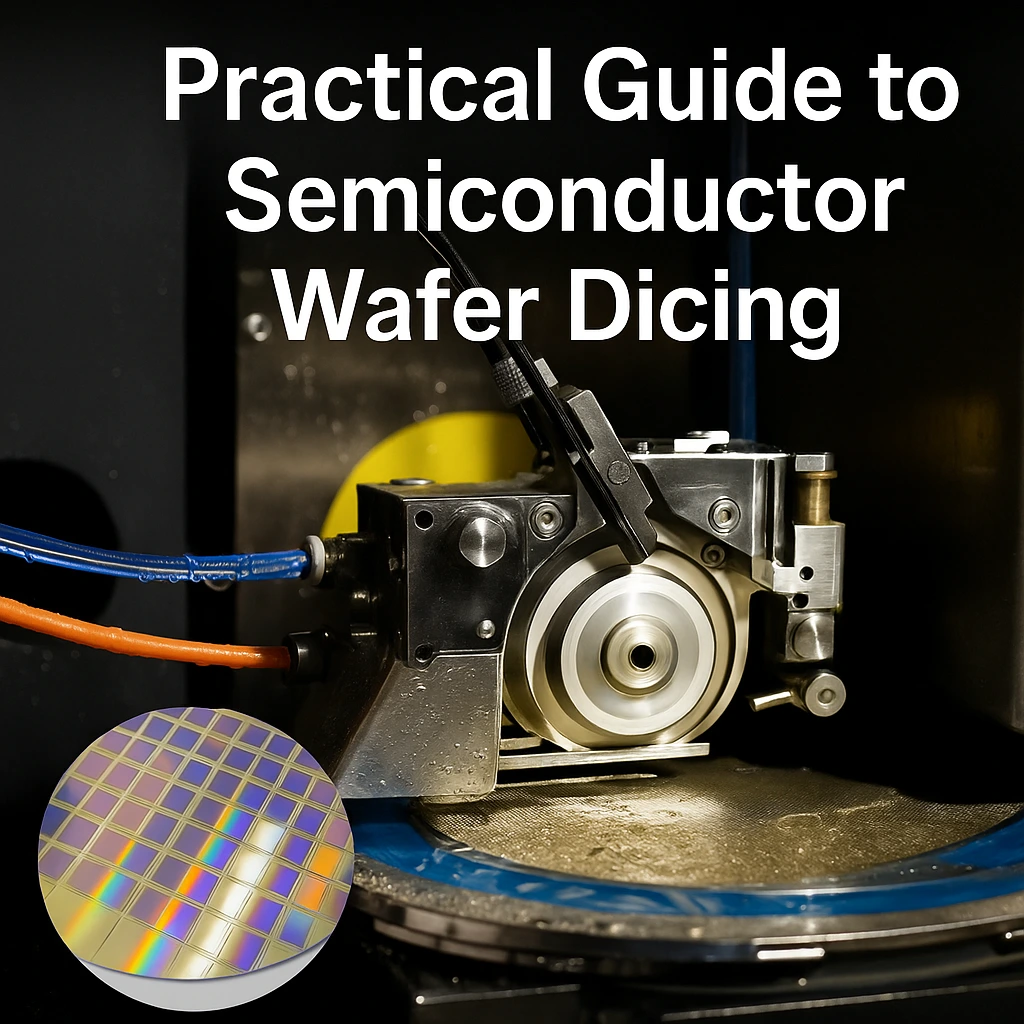
Practical Guide to Semiconductor Wafer Dicing: Materials, Blades, and Process Optimization
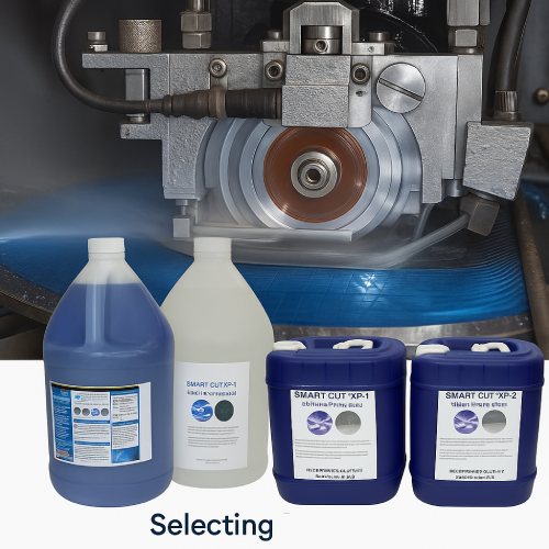
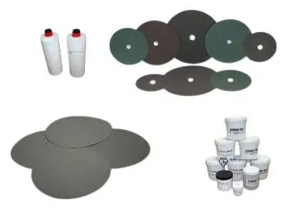
Selecting the Right Dicing Surfactant / Fluid for Your Application
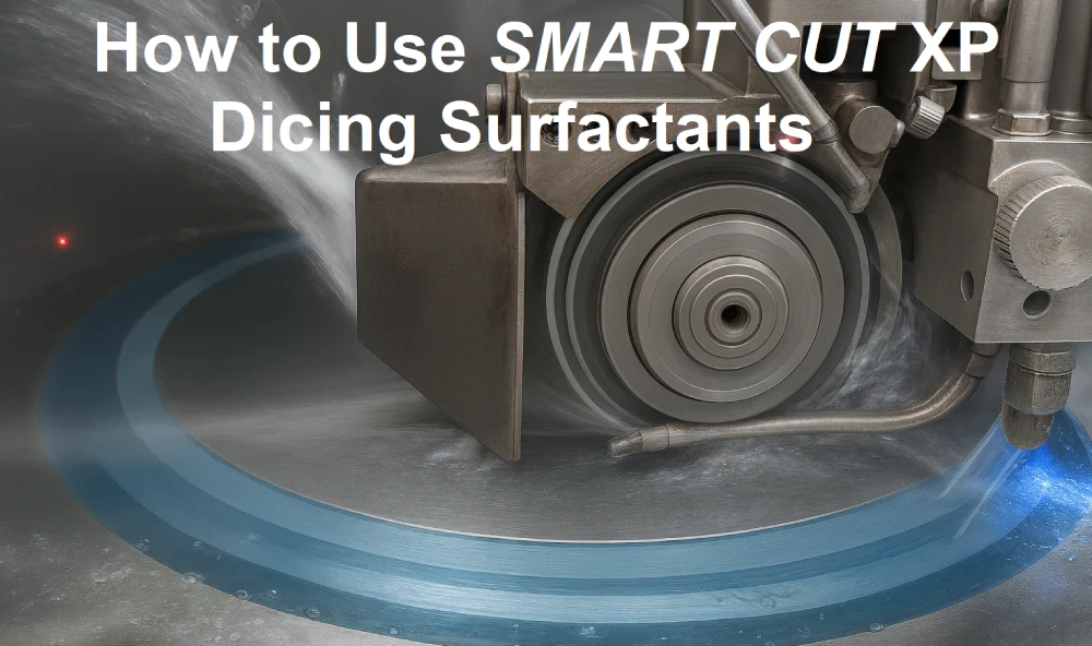
How to Use SMART CUT XP Dicing Surfactants
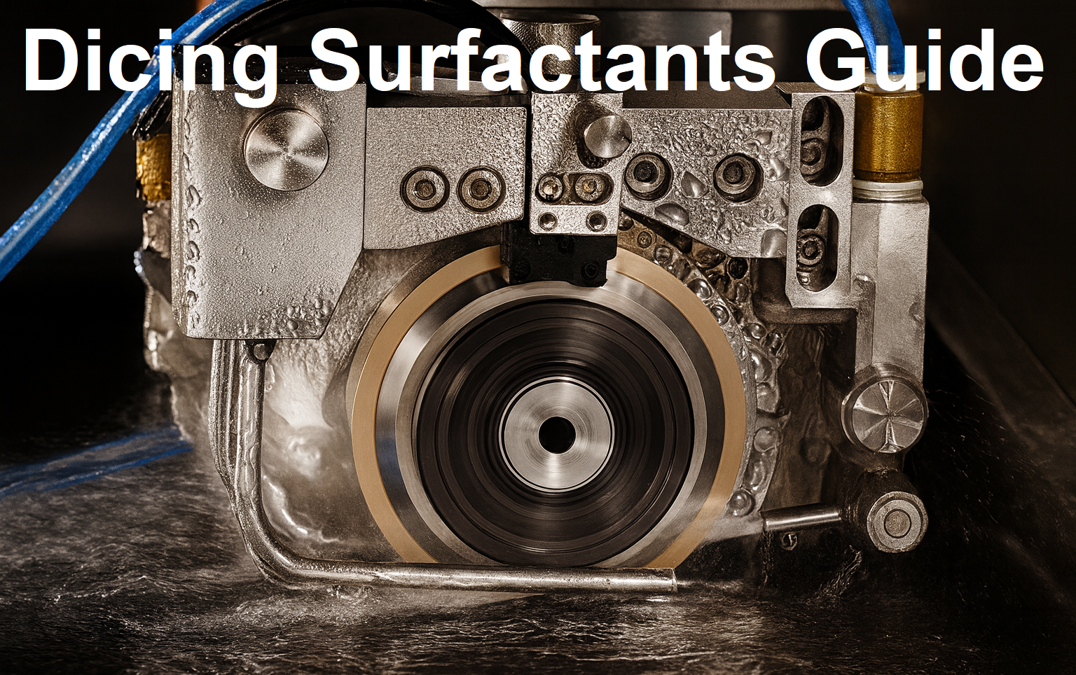
Dicing Surfactants Guide

Leon Meyer is a veteran manufacturing engineer and technical consultant with over 50 years of experience in the development, implementation, and troubleshooting of industrial diamond tooling systems. Having spent his career at the intersection of tool design, precision manufacturing, and production engineering, Mr. Meyer is widely regarded as one of the most experienced voices in the application of ultra-thin diamond blades, sintered core drills, and CBN grinding wheels across heavy industry, advanced materials, and research sectors.
Known for his pragmatic, no-nonsense approach, Leon has advised manufacturers across the United States, Europe, and East Asia—helping streamline cutting processes, extend tool life, and solve complex issues related to material breakage, chipping, and tolerance drift. His expertise has directly contributed to improved production efficiency in industries ranging from aerospace alloys and technical ceramics to optics, composites, and high-nickel superalloys.
As an author, Mr. Meyer brings a lifetime of field knowledge to his writing, with a focus on real-world problem solving, cost-performance optimization, and tool reliability under demanding conditions.