


Dicing Blade Operations Recommendations
-
Posted by
contactor6

Selecting the right dicing blade parameters often involves a trial and error process, many aspects of which can be mitigated through experience and a deep understanding of how to optimize these parameters for specific applications. What works for one application may not work for another. While there is no true substitute for experience, even new dicing saw operators can quickly become proficient by learning and applying some basic principles of dicing. Much of the content in this guide has been published in industry magazines or presented at conventions.
In order to get the most out of your dicing blade, it is crucial to read and follow these instructions and suggestions. Doing so will help you save both money and time. These recommendations come from years of experience in research, development, and manufacturing of dicing blades, as well as from personal experiences and observations with clients. The dicing blade itself is only a small part of your operation. Successful dicing is both an art and a science, requiring proper use and an understanding of how to select the right diamond dicing blade for your material and application. This guide covers key aspects such as maintaining and using the proper equipment, optimizing cutting parameters, and implementing best practices for blade maintenance and operation.
By following the guidance provided, you can enhance the efficiency and quality of your dicing operations, ultimately leading to better outcomes and reduced operational costs. Whether you are an experienced operator or new to the field, this comprehensive guide will equip you with the knowledge and techniques necessary for successful dicing blade operations.
Understanding Your Goals & Objectives
In preparing for a dicing operation, the most important aspect to start with is understanding your objectives. Clear objectives provide a foundation for all other decisions and actions in the process. Understanding your objectives is paramount because it defines success criteria and guides decision-making. Knowing your end goals helps define what a successful dicing operation looks like, including the desired quality of cuts, production speed, and yield. Objectives influence every decision from material selection to machine settings. For example, if high precision is a priority, it will affect the choice of blade, spindle speed, and cooling methods.
Material type is also crucial and is closely tied to your objectives. Different materials have different properties, such as hardness and brittleness, which affect how they should be diced. If the objective is to achieve minimal chipping, the material type will influence the blade selection and cutting parameters. For instance, dicing silicon wafers requires a different approach compared to ceramics or metals due to their distinct physical properties.

Dimensions of the material being diced impact the choice of blade and cutting speed. The size and thickness of the material directly affect operational setup. Thin wafers may need finer blades and slower feed rates to avoid breakage. Larger substrates may need specific fixtures or clamping methods to ensure stability during cutting, directly affecting the operational setup.
Understanding the capabilities of your dicing machine is essential for aligning with your objectives. Knowing what your machine can and cannot do will help you set realistic goals and avoid operational issues. Advanced machines with higher precision may be necessary for cutting materials that require very tight tolerances.
Blade selection is critical and should align with your material and cutting objectives. The type of dicing blade chosen, such as resin bond or nickel bond, affects cut quality and operational efficiency. For applications requiring smooth, precise cuts with minimal chipping, a resin-bonded blade might be more suitable.
To align objectives with operational preparation, define specific goals by clearly outlining what you need to achieve, whether it is a high yield, minimal material wastage, or the finest precision cuts. Assess the material properties to understand the material’s characteristics and how they affect the dicing process. Evaluate machine specifications to ensure your dicing equipment can meet the operational demands set by your objectives. Select appropriate equipment, choosing blades and fixtures that align with both the material properties and the operational goals. Finally, set parameters based on your objectives, including the appropriate cutting parameters such as spindle speed, feed rate, and cooling methods.
Selecting the Right Dicing Blade for Your Application
Choosing the appropriate dicing blade for your specific application requires careful consideration of several key variables. The type of material to be cut is fundamental, as different materials have varying hardness, brittleness, and composition, all of which influence the choice of the blade. For instance, silicon and other semiconductors require precision and minimal chipping, glass and ceramics need a blade that can handle their hardness without causing cracks, and metals require blades with a different bond and diamond concentration to cut efficiently.
The depth of the required cuts also influences the blade thickness and the bond type. Shallow cuts may allow for thinner blades, which offer higher precision, while deeper cuts might require thicker blades to maintain stability and reduce the risk of blade deflection.

Cut quality is another crucial factor, especially in high-precision industries like semiconductors and optics. The desired cut quality dictates the diamond grit size and concentration, with fine grit providing a smoother finish but cutting slower, and coarser grit cutting faster but potentially leaving rougher edges.
The equipment used, including its speed and RPM, plays a significant role in blade selection. Each blade is designed to operate efficiently at specific speeds. High RPM machines might require blades with stronger bonds to withstand the centrifugal forces, while lower RPM machines might benefit from softer bonds to ensure efficient cutting action.
Production output requirements affect blade choice as well. High output requirements might prioritize blades that offer longer life and higher durability, whereas low to medium output might allow for more frequent blade changes if it means achieving higher precision.
Other important factors include the blade bond or binder, which affects both the blade's life and its cutting efficiency. Different applications might require metal, resin, or hybrid bonds based on the material being cut and the required precision. Blade thickness is also crucial; thicker blades offer more stability but may cause wider kerfs and increased material loss, while thinner blades provide higher precision but may be prone to deflection under certain conditions.
The size of the diamond particles or abrasives matters too. Larger particles cut faster but might leave a rougher finish, whereas smaller particles provide a finer finish but might cut more slowly. Regular dressing of the blade ensures that the diamonds are exposed properly and maintain their cutting efficiency, as neglecting blade dressing can lead to reduced performance and shorter blade life.
Blade exposure, feed rate, spindle speed, and coolant supply are additional parameters that can impact cutting performance. Adjusting the exposure of the blade can optimize cutting for different materials and depths, and the speed at which the material is fed into the blade affects the quality and efficiency of the cut. Proper spindle speed ensures efficient cutting and reduces the risk of blade damage, while an adequate coolant supply is essential to prevent overheating, reduce friction, and prolong blade life.
When choosing the best dicing blade specification for your application, it is essential to remain objective and consider all the parameters discussed. While blade life and cut quality are typically the most important criteria for most users, other factors such as consistency, unit cost, lead time, availability, and technical support may have just as much priority, if not more importance, in the decision-making process. By carefully evaluating these variables and understanding their interdependencies, you can select a dicing blade that not only meets your immediate needs but also supports long-term efficiency and productivity.
Material Mounting in the Dicing Process
Material mounting is the critical first step in the dicing process, and using the correct mounting media is essential for achieving optimal results tailored to your specific application and requirements. There is a wide variety of mounting methods available, each suited to different dicing applications.
For high-volume dicing applications, UV tapes are typically the preferred choice. UV tapes provide strong adhesion during the dicing process and easy release once exposed to UV light, making them efficient for mass production. Conversely, for smaller applications, research and development tasks, or applications involving dicing small die and ceramics, waxing is often used to bond the wafer to a selected dicing substrate. This method allows for precise control and adjustment, making it ideal for delicate or experimental work.
Selecting the right mounting method plays a crucial role in optimizing your dicing application to achieve the highest level of efficiency. When the material is to be diced or scribed only partially (not all the way through), the mounting method's importance is reduced. However, when cutting through the material entirely, numerous variables must be controlled to ensure the best results. The primary goal should be to achieve good and uniform contact between the material and the tape, without the presence of air bubbles, dust, or dirt particles between the material and the mounting media.
Key Factors in Material Mounting
-
 1. Uniform Contact: Ensuring uniform contact between the material and the tape is critical. Any gaps or irregularities can cause instability during the dicing process, leading to inaccurate cuts or damage to the material.
-
2. Avoiding Contaminants: It is vital to avoid air bubbles, dust, and dirt particles between the material and the mounting media. These contaminants can create weak points or irregularities in the mounting, affecting the dicing accuracy and quality.
-
3. Curing Time: For methods like UV tapes or waxing, allowing adequate curing time is essential. This ensures the adhesive or wax has fully bonded with the material, providing a stable and secure mount.
-
4. Material-Specific Considerations: Different materials may require different mounting methods. For instance, delicate or brittle materials might need a softer mounting media to prevent stress and damage during the dicing process.
-
5. Application Type: The choice of mounting method may vary based on the application type. High-volume production might prioritize speed and efficiency, using UV tapes, while R&D or custom applications might require the precision and adjustability of waxing.
Techniques for Ensuring Proper Mounting
Regardless of whether a film frame or a ring is used, the mounting process is critical. Proper mounting ensures there are no air bubbles between the tape and the wafer, which can cause problems during dicing. Air bubbles can lead to material breakage or pieces falling off the tape. This issue arises because a vacuum is used during dicing; if there is a lump between the tape and the wafer, and the blade passes through this portion, it can break the blade or scratch the wafer.
To ensure proper mounting, start by thoroughly cleaning both the material and the mounting media to remove any contaminants. When using UV tapes, carefully apply the tape to avoid trapping air bubbles, and allow the necessary curing time before dicing. The tape should be placed close to the wafer without making contact initially. Using the fingertip, carefully press the tape onto the wafer, starting at one edge and working across until the entire wafer is mounted. This method ensures that the tape adheres evenly and securely, preventing air bubbles.
For waxing, evenly apply the wax to the substrate and the material, ensuring uniform coverage and contact. Once the material is mounted, verify the stability and adhesion by gently testing the bond before beginning the dicing process.
Whether using a film frame or a ring, proper mounting with the right kind of tape is crucial for preparing the material for dicing. Once mounted correctly, the wafer is ready for various processes such as scribing, notching, and full dicing. Proper mounting ensures stability and precision, which are essential for achieving high-quality cuts and minimizing material loss.
Proper material mounting sets the foundation for successful dicing operations. By selecting the appropriate mounting method and ensuring meticulous preparation, you can achieve high-quality, precise cuts and optimize the overall efficiency of your dicing application.
TAPE MOUNTING
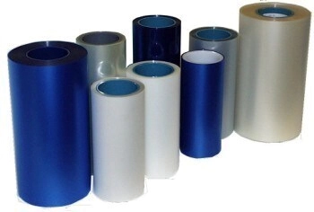
Tape is most common and frequently used mounting methods for majority of dicing applications. Tapes are preferred my majority of dicing applications, because of their ease of use, ease of handling, and fact that it can also be used later in die mounting process. Large variety of tapes are available today. Low strength, medium strength, and high strength tapes Mounting is done manually or utilizing wafer mounting systems.
Tapes are available with different adhesives with what is called “tackiness characteristics”. Adhesion characteristics of the most common tapes are 215-315 fr/25 mm. Tape thickness varies depending on application and material being diced. For example for cutting silicon wafers tape thickness of .010” (0.25mm) is typically used, where for thick alumna substrates tape thickness of .080 (2.03mm) is implemented
Low strength adhesive tapes are not recommended for cutting small dies, as well as large production applications. For these applications most users use medium and high strength adhesive tapes. Determining which tape to use for your application, sometimes may involve some trial and error.
For example the length of time the material or wafer will stay in contact with the mounting tape before and after dicing will determine whether to use medium or high strength tapes.
Wafer/material thickness is another consideration when selecting the right mounting adhesive. Very thin dies work well with waxes and medium strength tapes. Whereas, thicker wafers work better with medium to high strength tapes.
Cutting too deep into the mounting media will cause the blade to “load”. Minimize the depth in which the blade touches the mounting media. It is recommended to cut no more thane twenty five microns into the media. Cutting too deep into the media will cause premature blade failure. The blade can also agglomerate with the cutting media, resulting in chipping.
Selecting the Right Dicing tape for your application
Selecting the right dicing tape is crucial for the dicing process, as the correct choice can make or break a project. There are numerous options available, ensuring a tape for nearly every application. The key is understanding the characteristics of each type of tape and how they can be beneficial or counterproductive for your specific needs. Dicing tapes fall into two main categories: Standard and UV release. Most tapes are PVC-based films, and their adhesives are typically acrylic.
Standard Tapes:
These tapes are usually blue and lack a backing film, meaning the adhesive is exposed when the tape is peeled. They come in various thicknesses, from 80 microns to 130 microns, and different levels of tackiness. The adhesion level is measured in grams per millimeter (g/mm); the higher the number, the tackier the tape. The primary difference between standard tapes and UV release tapes is that standard tapes do not require UV light exposure to release the part. This can be advantageous or disadvantageous, depending on the application. For instance, using standard tape for a thick silicon wafer diced into very small pieces may result in the pieces coming off the tape during the dicing process, which could be disastrous. Conversely, if you have a standard-thickness wafer diced into larger pieces, it can be easily handled with standard blue tape without issues and without needing UV exposure. The type of material also plays a role, as some materials are more challenging to adhere to than others.
UV Release Tapes:
These tapes are typically clear and also come in various thicknesses. They have a backing film that needs to be peeled off before application. UV release tapes vary in tackiness before and after UV light exposure. This feature is essential when dealing with very thin wafers diced into small pieces; if the tape remains highly tacky even after UV exposure, it can be difficult to remove the fragile pieces. Generally, UV release tapes are ideal when strong adhesion during dicing is required, but an easy release is desired once exposed to UV light.
The thickness of the tape is critical because it affects the appropriate cut depth. Ensuring the correct tape thickness will prevent numerous issues with the final product. To determine the right tape, consider the material, material thickness, desired cut depth, blade thickness, and final die size. Evaluating these factors will help you select the appropriate tape for your application.
Another important consideration is that most dicing tapes, whether standard or UV release, require curing time. This means they need to sit for at least four hours before dicing to allow the adhesive to fully bond with the material. A common complaint is that parts come off the tape when the wafer is mounted and diced immediately. This issue can also be caused by air bubbles trapped between the part and the tape.
Holding Mediums for Tape and Wafer: Film Frame and Ring
In the dicing process, two main mediums are widely utilized to hold the tape and the wafer in place: film frame and ring. Each has its specific applications and advantages depending on the machine and system requirements.
Using Film Frame
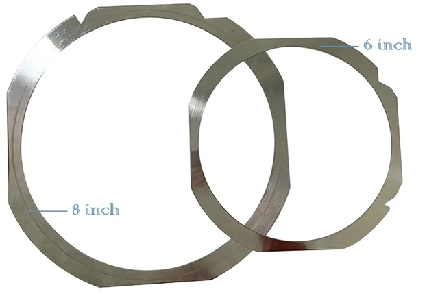
A film frame is a metal frame commonly used in various applications to hold wafers on the worktable or area. This medium caters to machines and systems that only accept this type of holding mechanism. Made from a single piece of metal, the tape adheres to the underside of the frame. Typically, the film frame is round, measuring about 0.050 inches thick, with notches at the bottom that fit into the machine's work area. The metal frame provides a sturdy and stable platform, ensuring that the wafer remains securely in place during the dicing process.
Using Ring
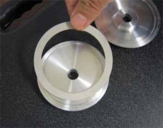
The ring is another material used to hold the tape and wafer. Unlike the film frame, the ring is a plastic hoop composed of two parts, similar to an embroidery ring. It consists of a small and a large diameter ring that assemble together, holding the tape between them while slightly stretching it once in place.
The ring mechanism securely holds the tape in a manner similar to how an embroidery hoop holds fabric. For example, an 8-inch diameter ring is commonly used for 6-inch and smaller wafers. The ring offers flexibility and ease of use, making it suitable for various dicing applications.
Wax/Glue Mounting to Media
Waxing or gluing materials to a solid medium is usually the most reliable and preferred form of mounting in dicing operations. This method offers several advantages that enhance the dicing process, especially when dealing with smaller die sizes and substrates that are not perfectly flat.
Wax/glue mounting provides improved holding characteristics, which is particularly beneficial when dicing smaller die sizes. This method effectively secures the material, reducing the risk of movement during the cutting process. Additionally, waxing or gluing eliminates the lip effect, which allows for cutting much deeper into the base material. This typically results in better cut quality, especially on the backside of the material.
One significant advantage of wax/glue mounting is that it prevents any die movement, which is crucial when performing a second index cut. This stability ensures that the dies remain in place, leading to more accurate and consistent cuts. The ability to mount substrates that are not perfectly flat is another benefit. The wax or glue compensates for uneven surfaces by filling in the gaps, providing a stable and secure hold on the material.
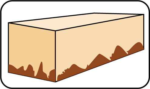
Different hardness base media can be used in conjunction with wax/glue mounting to control blade wear and simultaneously dress the blade. Common base media include glass or ceramic, which offer a stable and reliable surface for mounting. Wax mounting is particularly useful for mounting very thin and brittle materials. A variety of waxes are available for this purpose, including lumps, molded bricks, flakes, chips, and powders. Wax provides excellent adhesion to the supporting substrate, allowing for deep cutting into the substrate and often eliminating the lip effect and cracks at the bottom of the material. Additionally, wax expands as it fills in the gaps of a non-flat substrate, providing the best adhesion for the material or dies and resulting in superior cut quality and consistency.
Despite its advantages, wax mounting has some disadvantages. It can be a relatively messy process, particularly when removing the material and cleaning the dies afterward. The characteristics of waxes, such as melting point, flash point, specific gravity, structure, hardness, brittleness, flexibility, and elasticity, vary, making certain waxes better suited for specific applications than others.
Selecting the appropriate wax for a particular application is essential. High melting point waxes are suitable for materials that require strong adhesion and high-temperature stability, while lower melting point waxes are easier to clean and remove. The specific gravity and hardness of the wax also play a role in determining its suitability for different substrates and dicing requirements.
In practice, wax mounting involves heating the wax to its melting point and applying it to the substrate. The material to be diced is then placed on the wax, ensuring even contact and adhesion. Once the wax cools and solidifies, it securely holds the material in place during the dicing process. After dicing, the wax can be removed by reheating or using a suitable solvent, followed by cleaning the dies to remove any residual wax.
Mechanical Clamping/Fixturing
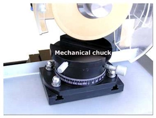
Mechanical clamping is an essential method for holding materials in place during dicing operations, especially when dealing with materials that have uneven shapes or geometries unsuitable for other mounting methods such as waxing or gluing. This method involves using various clamps and fixtures to secure the material firmly on the dicing machine’s worktable, providing stability and precision during cutting.
Advantages of Mechanical Clamping
One of the primary advantages of mechanical clamping is its versatility in handling materials with irregular shapes. When the geometry of the material is uneven, mechanical clamps can be adjusted to hold the material securely, ensuring it remains stationary during the dicing process. This adaptability makes mechanical clamping a preferred choice for a wide range of applications, including those where traditional mounting methods are impractical.
Mechanical clamping also offers several benefits for more standardized or flat materials. The ease of use, loading, and unloading provided by mechanical fixtures enhances operational efficiency. Unlike adhesive-based methods, mechanical clamping does not require drying or curing time, allowing for faster setup and turnaround. This efficiency is particularly beneficial in high-volume production environments where minimizing downtime is crucial.
Additionally, mechanical clamping systems can be quickly adjusted and repositioned, making them ideal for applications that require frequent changes in material or cutting specifications. This flexibility reduces setup time and increases overall productivity, as operators can swiftly move from one task to another without extensive reconfiguration.
Challenges of Mechanical Clamping
Despite its advantages, mechanical clamping does present certain challenges. One significant issue is the potential for chipping at the bottom of the cut. This problem arises because the backside of the material does not have firm support at the cutting area, leading to increased chipping rates. When the blade reaches the bottom of the material, the lack of support can cause the material to fracture or chip, compromising the quality of the cut.
To mitigate this issue, several strategies can be employed. One approach is to use a sacrificial backing material that provides additional support to the underside of the material being cut. This backing material absorbs the cutting forces and helps reduce chipping, resulting in cleaner cuts. Selecting a backing material that is easy to remove or does not adhere strongly to the material can further streamline the process.
Another strategy is to optimize the clamping pressure. Applying uniform and sufficient clamping force can help stabilize the material and minimize movement during cutting. However, care must be taken to avoid excessive pressure that could deform or damage the material. Using adjustable clamps and fixtures that can be precisely controlled allows operators to find the optimal balance between stability and pressure.
Enhancing the blade and spindle alignment is also critical in reducing chipping. Ensuring that the blade is perfectly aligned with the material minimizes lateral forces that can contribute to chipping. Regular maintenance and calibration of the dicing machine are essential to maintaining this alignment and achieving consistent, high-quality cuts.
In practice, implementing mechanical clamping requires selecting the appropriate fixtures and clamps based on the material's geometry and cutting requirements. For materials with uneven shapes, customized fixtures may be necessary to ensure a secure hold. For standardized materials, adjustable clamps and modular fixturing systems offer the flexibility needed to accommodate different sizes and shapes.
Operators should also be trained in the proper setup and adjustment of mechanical clamping systems. Understanding the material properties and cutting dynamics helps in making informed decisions about clamping pressure and positioning. Additionally, regular inspection and maintenance of the clamping system ensure that it remains in good working condition and continues to provide reliable performance.
Securing the Material
Securing the material correctly is fundamental to prevent movement during cutting, which can lead to inaccuracies, blade damage, and compromised safety. The method of securing the material depends on the type and size of the workpiece, as well as the dicing machine being used.
Start by selecting the appropriate fixtures or clamps designed for the specific material and dicing setup. Ensure the fixtures are clean and free from debris to prevent any interference with the securing process. Position the workpiece carefully on the dicing platform, aligning it according to the desired cutting path. Use precision alignment tools or guides to achieve accurate positioning.
Once the material is in place, use the clamps or fixtures to hold it securely. Apply even pressure to avoid deforming or damaging the material. For thin or delicate materials, consider using vacuum chucks, which provide a uniform and gentle hold without physical clamps. Verify that the material is stable and cannot move or shift during cutting by gently testing its position.
In some cases, using double-sided adhesive tapes or specialized adhesives can help secure smaller or irregularly shaped workpieces. Ensure that the adhesive used does not leave residues that could interfere with the cutting process or damage the material.
Cleaning and Conditioning the Surface
Cleaning and conditioning the surface of the workpiece are crucial steps to ensure a smooth and precise cutting process. Any contaminants, residues, or surface irregularities can affect the blade's performance and the quality of the cut.
Begin by thoroughly cleaning the workpiece surface to remove dust, dirt, oils, and other contaminants. Use appropriate cleaning agents based on the material being processed. For most materials, a gentle solvent such as isopropyl alcohol can effectively clean the surface without causing damage. Apply the cleaning agent using a lint-free cloth or soft brush, ensuring complete coverage and removal of contaminants.
For more stubborn residues or for materials that are sensitive to certain chemicals, use specialized cleaning solutions designed for that specific material. Follow the manufacturer's recommendations for the cleaning agents and procedures to avoid any adverse reactions or damage to the workpiece.
After cleaning, inspect the surface for any remaining particles or imperfections. Use a magnifying glass or microscope if necessary to ensure the surface is completely clean. Any remaining contaminants can interfere with the cutting process, leading to poor cut quality and potential blade damage.
Conditioning the surface involves treating it to achieve optimal cutting conditions. For some materials, this may include applying a surface coating or lubricant to reduce friction and enhance cutting efficiency. Ensure that any conditioning agents used are compatible with both the material and the diamond blade.
In cases where the workpiece surface has imperfections or irregularities, consider performing a preliminary smoothing or polishing step to create a uniform surface. This can help in achieving more consistent cuts and reducing the risk of blade wear or damage.
Finally, allow the workpiece to dry completely if any liquids were used during cleaning and conditioning. Residual moisture can affect the adhesion of tapes or adhesives used for securing the material and may also impact the cutting process.
By thoroughly securing the material and ensuring a clean and conditioned surface, users can achieve precise, high-quality cuts with diamond dicing blades. Proper preparation of the workpiece minimizes the risk of errors, enhances blade performance, and ensures a smooth and efficient cutting process.
Mounting the Blade
Mounting the blade correctly is crucial for ensuring optimal performance and safety when using diamond dicing blades. Proper alignment and secure attachment are essential steps in this process.

Using the Right Flanges
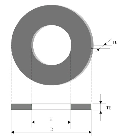
Selecting the appropriate flanges for diamond dicing blades is essential for ensuring optimal performance and precision. The right flanges provide stability, reduce vibration, and ensure accurate blade alignment. Flanges should be chosen based on the blade size, thickness, and the specific requirements of the cutting application. Typically made from durable materials such as stainless steel or aluminum, flanges must be robust enough to withstand operational stresses. The inner diameter should match the spindle size, while the outer diameter should support the blade adequately without interfering with the cutting process. Proper flange thickness is crucial for maintaining blade stability and minimizing deflection during cutting.
Properly Mounting the Blade on Flanges
Properly mounting the blade on the flanges is crucial to ensure accurate and safe operation. Begin by thoroughly cleaning the blade, flanges, and spindle to remove any debris, dust, or residues that might interfere with alignment. Place the blade between the flanges, ensuring it sits evenly without any tilt, lying flat against the inner surface of the flanges. Carefully align the flanges so that they are concentric with the blade and spindle, as misalignment can cause wobbling and reduce cutting accuracy. Tighten the screws or bolts evenly in a crisscross pattern to apply uniform pressure across the blade, avoiding over-tightening, which can warp the blade, or under-tightening, which can cause slippage.
Dicing Blade Exposure
The amount of blade exposed beyond the flanges significantly impacts cutting performance and blade life. Proper blade exposure ensures effective cutting while minimizing stress on the blade. The blade exposure should be slightly greater than the thickness of the material being cut. Excessive exposure can lead to blade deflection, while insufficient exposure might cause incomplete cuts. Use the machine’s adjustment mechanisms to set the blade exposure, measuring the exposure accurately using a caliper or a ruler. Ensure the blade exposure is uniform along the entire circumference, as inconsistent exposure can lead to uneven cuts and increased blade wear. Once the desired exposure is set, ensure the blade is securely locked in place and double-check the tightness of the mounting screws or bolts.
Proper Alignment
Achieving proper alignment when mounting a diamond dicing blade is critical to prevent uneven cuts, excessive wear, and potential damage to both the blade and the workpiece. Begin by thoroughly cleaning the spindle and flange surfaces to remove any debris, dust, or residue that might interfere with the blade's alignment. Any particles left on these surfaces can cause misalignment and affect the precision of the cuts.
Next, carefully place the blade onto the spindle, ensuring it is seated properly and lies flat against the flange. The blade should fit snugly without any gaps or uneven contact points. Check the blade's position from multiple angles to confirm that it is perfectly aligned. Use alignment tools or gauges if available to ensure accuracy. Some advanced dicing machines may come equipped with automatic alignment systems that can assist in achieving precise blade positioning.
Once the blade is positioned, gradually tighten the flange or locking mechanism. It is important to tighten the bolts or screws evenly and in a crisscross pattern to maintain even pressure across the blade. Uneven tightening can lead to blade wobble or misalignment, which can negatively impact the cutting process. After securing the blade, manually rotate it to check for any signs of wobble or misalignment. If any issues are detected, loosen the flange, realign the blade, and retighten it.
Ensuring Secure and Stable Attachment
Ensuring that the blade is securely and stably attached is vital for safe and effective operation. Begin by verifying that the mounting hardware, such as flanges, bolts, and screws, are in good condition and free from wear or damage. Damaged or worn mounting components can compromise the stability of the blade attachment and pose safety risks.
After the blade is aligned, make sure that all locking mechanisms are properly engaged. Double-check that the flange or clamping mechanism is securely fastened and that there is no play or movement in the blade. It is crucial to follow the manufacturer's torque specifications when tightening the mounting hardware to avoid over-tightening, which can damage the blade, or under-tightening, which can result in an insecure attachment.
To further ensure stability, inspect the spindle and other mounting components for any signs of wear or damage before mounting the blade. A well-maintained spindle will help maintain the blade's stability and alignment during operation. Regular maintenance and inspection of these components are essential to prevent issues that could affect the cutting process.
Once the blade is securely mounted, perform a trial run at low speed to verify the stability and alignment of the blade. Listen for any unusual noises and observe the blade's movement. If the blade operates smoothly without any wobbling or irregularities, gradually increase the speed to the recommended operating level.
Finally, implement a routine check before each use to ensure the blade remains securely attached and properly aligned. Regularly inspect the mounting hardware and the blade itself for any signs of wear or loosening. By following these steps, users can ensure that their diamond dicing blade is mounted correctly, leading to improved cutting precision, enhanced blade life, and a safer working environment.
Machine Calibration
Proper machine calibration is fundamental to achieving optimal performance and precision when using diamond dicing blades. Correctly setting spindle speeds, feed rates, and depths of cut are critical steps in this process to ensure high-quality cuts and extended blade life.
Setting Appropriate Spindle Speeds
Setting the appropriate spindle speed is crucial for ensuring efficient cutting and maintaining the integrity of both the blade and the workpiece. The spindle speed directly affects the cutting rate, heat generation, and wear on the blade. To set the correct spindle speed, start by consulting the manufacturer's recommendations for both the blade and the material being cut. These guidelines provide a baseline for optimal performance.
The type of material being cut plays a significant role in determining the spindle speed. Harder materials, such as ceramics and semiconductors, typically require lower spindle speeds to minimize heat generation and prevent blade wear. Softer materials can generally be cut at higher spindle speeds. Additionally, the thickness and hardness of the material should be considered; thicker or harder materials may necessitate slower speeds to ensure a smooth and precise cut.
Modern dicing machines often come equipped with digital controls that allow for precise adjustments of spindle speeds. Use these controls to set the speed accurately, starting at a lower speed to observe the cutting performance. Gradually increase the speed if necessary, while monitoring the blade's behavior and the quality of the cut. Pay attention to any signs of excessive heat, noise, or vibration, which may indicate an inappropriate spindle speed.
Adjusting Feed Rates and Depths of Cut
Feed rates and depths of cut are equally important in the calibration process. Proper adjustment of these parameters ensures efficient material removal, minimizes blade wear, and maintains the quality of the cuts.
Feed Rates:
To set the correct feed rate, consider the material's properties and the desired cut quality. The feed rate determines how quickly the material is fed into the blade, affecting the cutting speed and surface finish. Start by setting a conservative feed rate based on the manufacturer's recommendations. A slower feed rate reduces the risk of blade damage and improves control over the cutting process, especially for delicate or brittle materials.
Monitor the cutting process closely to evaluate the performance. If the cut quality is acceptable and there are no signs of blade stress or material damage, you may gradually increase the feed rate to enhance productivity. However, avoid excessive feed rates that can lead to poor cut quality, increased blade wear, and potential breakage. Utilize the machine's feed rate controls to make precise adjustments and ensure consistent feeding.
Depths of Cut:
Adjusting the depth of cut is critical for achieving the desired cut without overloading the blade. The depth of cut refers to how deep the blade penetrates the material in a single pass. Set the initial depth of cut based on the material thickness and blade specifications. For thicker materials, it is often advisable to perform multiple shallow passes rather than a single deep cut to reduce stress on the blade and improve cut accuracy.
Ensure that the depth of cut does not exceed the blade's capacity, as this can cause excessive wear and potential damage. Use the machine's depth control settings to make precise adjustments, and verify the depth of cut by performing test cuts and inspecting the results. Shallow cuts help maintain blade sharpness and minimize the risk of chipping or cracking the material.

Continuous Monitoring and Adjustment
Machine calibration is not a one-time process but requires continuous monitoring and adjustment to maintain optimal cutting conditions. Regularly check the spindle speed, feed rate, and depth of cut during operation to ensure they remain within the desired parameters. Utilize the machine's monitoring systems to track performance metrics such as spindle load, cutting temperature, and blade wear.
Make incremental adjustments as needed based on real-time observations and feedback. If any deviations from the expected performance are detected, investigate and address the underlying causes promptly. Regular calibration checks, combined with proactive maintenance, help in sustaining high cutting efficiency and extending the lifespan of diamond dicing blades.
By meticulously setting the spindle speeds, adjusting the feed rates, and depths of cut, and continuously monitoring these parameters, users can achieve superior cutting performance, enhance blade longevity, and ensure consistent, high-quality results in their dicing operations
Operational Best Practices
Properly initiating the cutting process is crucial for achieving precise and high-quality results when using diamond dicing blades. Begin by gradually bringing the diamond dicing blade into contact with the material. Sudden engagement can cause chipping or cracking, especially with brittle materials like ceramics or silicon wafers. Use a slow and controlled feed rate when initiating the cut to establish a clean starting edge and reduce stress on the blade and material. The feed rate can be gradually increased once the initial groove is established.
Pay close attention to any unusual vibrations or noise during the initial engagement. Excessive vibration or noise can indicate improper alignment or excessive pressure, which can damage both the blade and the material. Ensure that the spindle speed is set according to the manufacturer's recommendations for the specific material and blade type. Starting with a lower speed and gradually increasing it can help achieve a smooth cut.
Monitoring Initial Performance
Perform a visual inspection of the initial cut to ensure it is clean and free of defects. Look for signs of chipping, cracking, or uneven edges, which can indicate improper setup or blade issues. Evaluate the quality of the cut by checking for burr formation or surface roughness. High-quality cuts should have minimal burrs and a smooth surface finish.
Regularly inspect the blade for signs of wear or damage during the initial stages of cutting. Any abnormalities, such as excessive wear, deformation, or missing segments, should be addressed immediately to prevent further issues. Utilize any available machine monitoring systems to track parameters such as spindle load, temperature, and vibration. Real-time data can provide valuable insights into the cutting process and help in making necessary adjustments.
Establish a feedback loop to continuously monitor and adjust cutting parameters. This includes making incremental changes to feed rate, spindle speed, and cooling to optimize performance based on the initial observations. By following these best practices for starting the cut and monitoring initial performance, users can ensure a smooth and efficient cutting process, leading to superior quality and longevity of both the diamond dicing blade and the workpiece.
Maintaining Optimal Cutting Conditions
To maintain optimal cutting conditions, it is essential to continuously monitor and adjust various parameters. Constant feed rates are vital for consistent cutting performance. Fluctuations in feed rate can lead to uneven cuts, increased blade wear, and potential damage to the workpiece. Ensure the feed rate remains steady and is appropriate for the material being cut.
Cooling and lubrication play critical roles in the cutting process. Proper cooling helps in dissipating heat generated during cutting, reducing the risk of thermal damage to both the blade and the material. Use suitable coolants as recommended for the specific application, and ensure they are applied correctly to the cutting zone. Lubrication helps in reducing friction, which minimizes blade wear and improves the overall cutting efficiency.
Regularly monitor blade wear to prevent unexpected failures. Implement a schedule for inspecting the blade's condition, looking for signs of wear such as reduced cutting efficiency, increased noise, or visible damage. Replace the blade as needed to maintain cutting performance and prevent potential damage to the workpiece.
Troubleshooting Common Issues
When encountering issues such as blade chipping or cracking, it is crucial to identify the underlying causes and implement preventive measures. Common causes include excessive cutting pressure, improper blade alignment, or using the wrong blade type for the material. Addressing these factors can help in preventing recurrence.

Poor cut quality can arise from various factors such as incorrect spindle speed, inappropriate feed rate, or inadequate cooling. Analyzing these parameters and making necessary adjustments can improve the cut quality. Additionally, ensure the material is securely clamped and properly supported to avoid movement during cutting.
Excessive blade wear can result from cutting very hard or abrasive materials, using incorrect cutting parameters, or insufficient cooling. Identifying the contributing factors and implementing corrective actions, such as adjusting feed rates, using appropriate coolants, and selecting the right blade type, can extend blade life.
Maintaining Optimal Cutting Conditions
Maintaining optimal cutting conditions is vital for achieving consistent, high-quality results when using diamond dicing blades. Two key factors that significantly influence the cutting process are maintaining constant feed rates and ensuring appropriate cooling and lubrication.
Constant Feed Rates
Constant feed rates are essential for uniform cutting performance and longevity of the diamond dicing blade. Fluctuations in feed rate can lead to several issues, including uneven cuts, increased blade wear, and potential damage to the workpiece. To maintain a steady movement, ensure that the movement of the workpiece relative to the blade is smooth and continuous. Sudden changes in feed rate can cause stress on the blade and the material, leading to chipping or cracking.
Utilize automated feed systems where possible, as they can provide precise control over feed rates, minimizing human error and ensuring consistency. Many advanced dicing saws come equipped with computerized controls that allow for the setting and maintaining of exact feed rates. If using manual controls, operators should be trained to maintain a steady hand and consistent speed, as any variations in manual feed can adversely affect the cut quality and blade condition.
Continuously monitor the feed rate throughout the cutting process. Use sensors and feedback systems to detect any deviations and make real-time adjustments as necessary. This is particularly important when cutting materials with variable hardness or thickness. Different materials may require different feed rates, so consult the manufacturer's recommendations for optimal feed rates based on the material being cut. Adjust the feed rate to match the material properties to avoid excessive blade wear and ensure a clean cut.
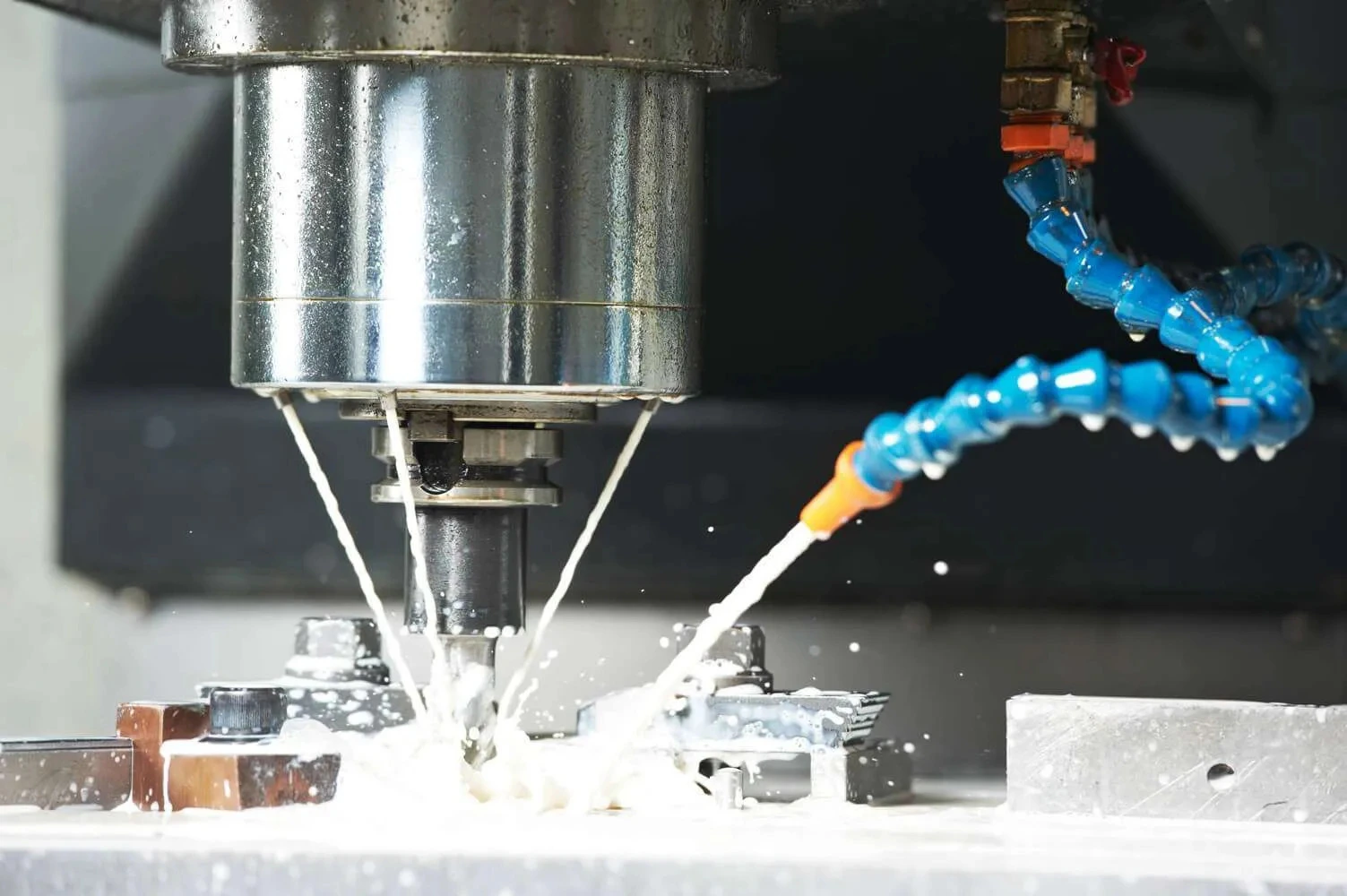
The Importance of Coolant Flow in Dicing Operations
The amount and supply of coolant can vary in importance depending on the material being cut and the type of dicing blade used. For instance, when cutting silicon with nickel-bonded dicing blades, the coolant amount and supply are generally of lesser importance. Most dicing saw operators use deionized water for this application. If the wafers are sensitive to electrostatic charges, the required conductivity is set using CO2. In such cases, a single nozzle may suffice for adequate cooling.
However, when cutting ultra-hard and brittle materials, the coolant flow direction and position play a significant role in determining blade life and performance. Proper coolant application can greatly influence the efficiency and effectiveness of the cutting process.
Coolant Application for Ultra-Hard and Brittle Materials
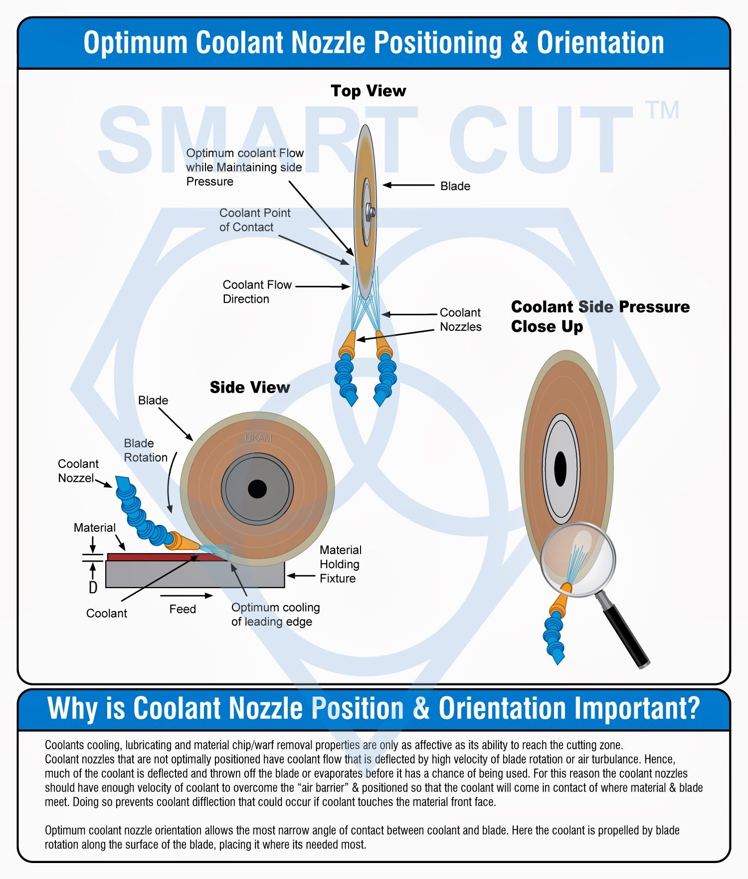
For cutting ultra-hard and brittle materials, a dual nozzle configuration is often the best choice to supply an adequate amount of coolant at the point of contact between the blade and the material. This setup involves directing coolant streams at both the blade's point of contact and the leading edge. The dual nozzle system provides two separate streams of coolant into the cutting zone, each angled towards the cutting edge of the blade, effectively cooling both sides of the blade. The nozzles should be positioned as close as possible to the point where the blade enters the substrate. This proximity ensures that the coolant flow blasts with high velocity into the kerf, effectively removing debris and preventing wide kerfs and premature blade wear. Improper coolant amount or flow at the cutting zone can lead to these issues, compromising both cut quality and blade life. By correctly positioning the coolant streams in front of the blade, the coolant will flow over the top of the material, enhancing the cooling effect and debris removal. Additionally, the coolant will be drawn into the kerf, providing further cooling and lubrication to the blade and cutting zone.
Key Considerations for Coolant Flow

The choice of coolant is critical. Deionized water is commonly used for cutting silicon, while specialized coolants may be required for other materials. Ensuring the correct type of coolant helps in maintaining blade performance and material integrity. For materials sensitive to electrostatic charges, adjusting the conductivity of the coolant using CO2 or other methods is essential. This adjustment prevents electrostatic buildup, which can damage sensitive wafers. A dual nozzle configuration is ideal for ultra-hard and brittle materials. This setup ensures that coolant is applied to both sides of the blade, providing balanced cooling and enhancing blade life and performance. Positioning the nozzles as close to the cutting point as possible ensures that coolant is effectively directed into the kerf. This placement maximizes the cooling effect and debris removal efficiency. High-velocity coolant streams are crucial for blasting debris out of the kerf and preventing buildup. This helps maintain a clean cutting zone and reduces the risk of blade damage. The flow rate of the coolant should be sufficient to maintain a stable temperature in the cutting zone and provide adequate lubrication. Regular monitoring and adjustment of the flow rate are necessary to ensure optimal performance.
Benefits of Proper Coolant Application
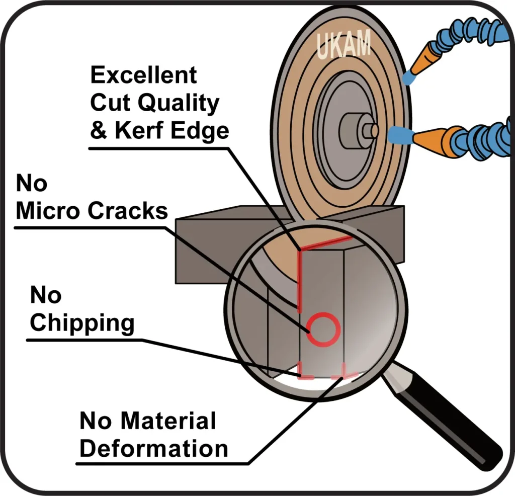
Proper coolant application provides several benefits, including improved blade life, enhanced cut quality, and increased operational efficiency. By maintaining the correct coolant flow and positioning, operators can achieve reduced blade wear, improved cut quality, increased productivity, and enhanced safety. Effective cooling reduces thermal stress on the blade, minimizing wear and extending its lifespan. Proper lubrication and debris removal result in cleaner cuts with fewer defects. Efficient cooling allows for faster cutting speeds without compromising quality, improving overall productivity. Proper coolant flow reduces the risk of overheating and blade failure, contributing to a safer working environment.

When implementing a coolant system for dicing operations, design the coolant delivery system with dual nozzles for ultra-hard and brittle materials. Ensure that the system is capable of providing high-velocity coolant streams. Regularly inspect and maintain the coolant system to prevent blockages and ensure consistent flow. Clean and replace nozzles as needed to maintain optimal performance. Continuously monitor coolant levels, flow rates, and system performance. Use sensors and feedback systems to detect any issues and make necessary adjustments. Train operators on the importance of coolant application and proper system maintenance. Ensure they understand how to adjust the system for different materials and cutting conditions.
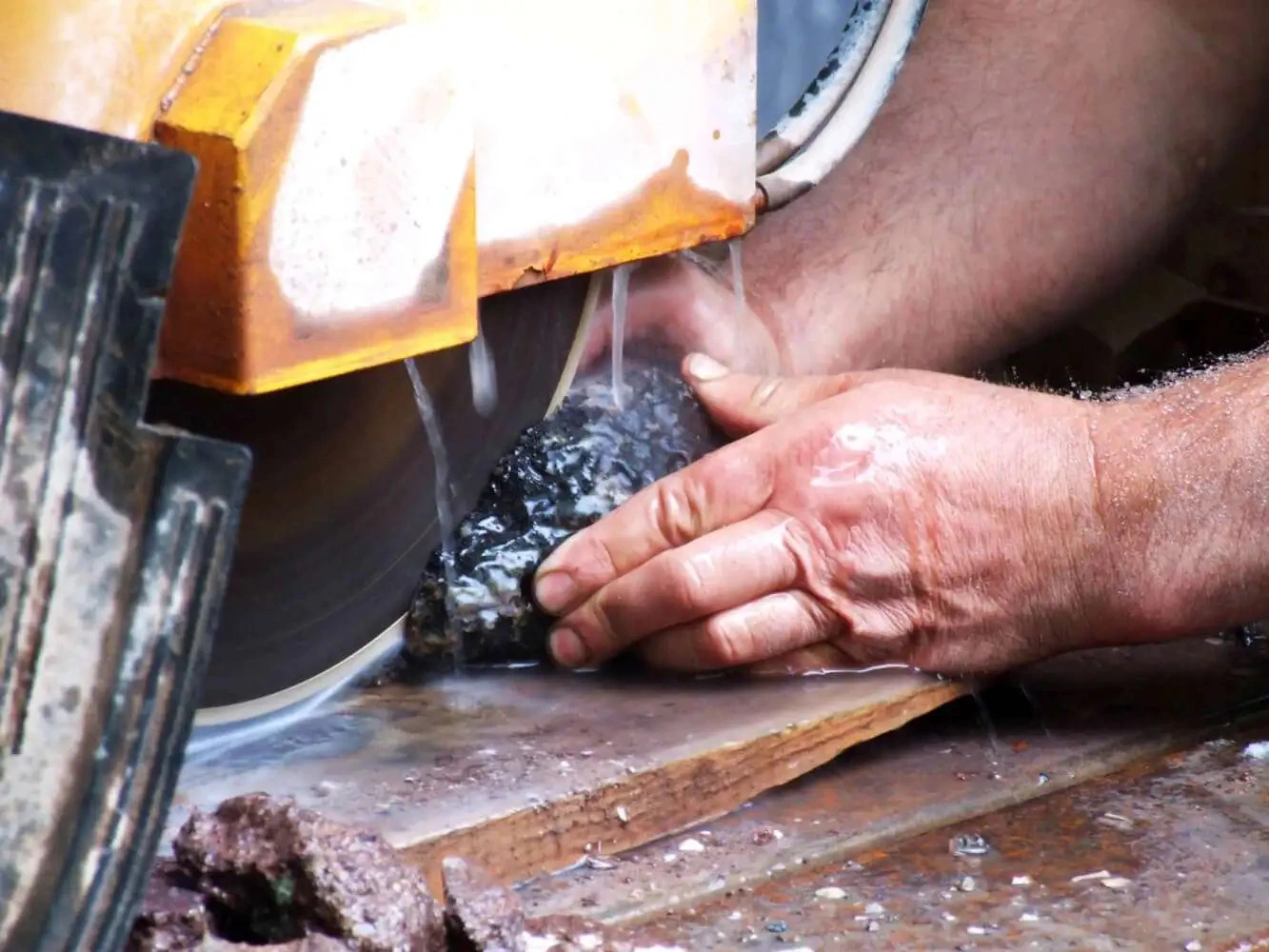
Cutting Direction
When cutting silicon, the direction of cutting is generally not critically important. Most wafers are cut by moving the table back and forth, which is effective for this relatively softer material. However, when dealing with hard and brittle materials, the cutting approach must be adjusted to optimize cut quality and minimize damage.

For hard and brittle materials, the blade should enter the material in a "cutting down" direction. As the blade penetrates the surface, the chips removed by the diamond particles become progressively smaller the deeper the blade cuts. This method helps maintain optimal cut quality by reducing chipping and distributing the cutting force more evenly. In contrast, cutting in the opposite direction, where the blade enters the substrate almost tangentially, results in different dynamics. Initially, the chips removed are small, but their size increases towards the exit point of the blade, leading to significant chipping at the surface. Cutting in the upward direction creates more edge chipping and increases spindle torque, making the process less efficient and more damaging to the material.
Coolant Application for Thicker Materials
Cutting thicker materials, those over 0.100 inches (2.54 mm), presents additional challenges for both the dicing blade and the coolant supply. Ensuring sufficient coolant reaches the bottom of the cutting zone is crucial for effective cooling and lubrication.
One effective solution is using specially formulated water-soluble dicing coolants. These coolants lower the surface tension of the water, helping it penetrate the full depth of the kerf more effectively. This enhanced penetration not only improves cooling but also acts as a lubricant, reducing the load on the blade and minimizing wear. Another approach involves using specialized flange sets designed to optimize coolant delivery. These flanges help direct the coolant more precisely to the cutting zone, ensuring that it reaches the entire depth of the cut. This method helps maintain blade performance and prolongs blade life by ensuring effective cooling and lubrication throughout the cutting process.
Appropriate Cooling and Lubrication
Coolant is one of the most overlooked variables in the overall dicing process. Effective and proper use of coolant and recalculating coolant system will pay off in terms of improved surface finish quality, increased blade life and more consistent cutting results.
Coolant does more than just cool the blade and material, it other more important roles include: lubrication, flush away swarf particles. For most affective use of coolant the quality of water being used, coolant concentration, and maintenance of the coolant tank makes a difference. Different geographic areas have different water harnesses.
Proper cooling helps dissipate heat generated during cutting, reducing the risk of thermal damage to the blade and the material. Lubrication reduces friction, minimizing blade wear and enhancing cutting efficiency.
Use appropriate cooling methods, such as liquid coolant flow, to effectively dissipate heat. Coolants can be applied directly to the cutting zone to maintain a stable temperature and prevent overheating. Ensure that the coolant flow is consistent and adequately covers the cutting area. Select the right type of coolant for the specific application. Water-based coolants are commonly used for most materials, but specialized coolants may be required for certain applications, such as cutting highly reactive or sensitive materials.

Implement efficient coolant delivery systems to ensure even distribution of coolant across the cutting area. Use nozzles, sprayers, or other delivery mechanisms designed to provide uniform coverage. Regularly inspect and maintain the delivery system to prevent blockages or malfunctions. Proper lubrication reduces friction between the blade and the material, decreasing wear and improving cut quality. Lubricants can be added to the coolant or applied separately, depending on the cutting requirements and material properties.
Regularly check coolant levels and quality to ensure effective cooling and lubrication. Contaminated or depleted coolant can lead to poor cutting performance and increased blade wear. Replace or replenish coolant as needed to maintain optimal conditions. Maintain a controlled environment to support effective cooling and lubrication. Factors such as ambient temperature, humidity, and airflow can impact the efficiency of cooling and lubrication systems. Ensure that the cutting area is well-ventilated and free from excessive heat or moisture.
Water containing less than six grains of dissolved minerals per gallon is considered soft water, water containing more then seventeen grains per gallon is considered hard. The best coolant water to use in a coolant system is chemically pure water, which is free of all dissolved solids. Chemically pure water and reverse osmosis. Reverse osmosis is the method most recommended by coolant manufacturers, however not always available. Deionized water offers much improvement over available plant water.
Water in the tank can evaporate and remaining water can become harder. Hard water affects coolant capabilities in many ways decreased capability to the rust inhibitor, increased foaming, formation of a sticky residue, and increased bacteria counts. Coolant concentration should be controlled and maintained to ensure that the coolant is being used at optimum efficiency. Too little coolant in the tank will lead to corrosion and rancidity, while too high of a concentration can also cause foaming. Maintenance of the re-circulating tank is also critical to coolant performance. Cleaning he tank is a dirty job, but if done often enough and thoroughly, it can increase the performance of your dicing saw. Keeping he coolant tank clean will ensure that you are getting the most form your coolant, keeping corrosion and bacterial growth a bay while providing the necessary coolant, lubrication and protection of your blades and material.
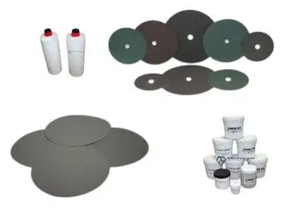
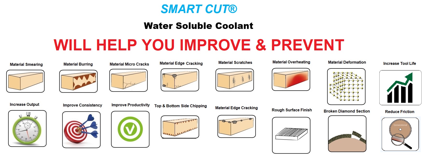
SMART CUT® XP Dicing Fluid, Coolant, & Surfactant
Available in 4 Different Formulas to Fit Most Dicing Applications
XP-1 is a general-purpose dicing fluid within the SMART CUT® range, designed to reduce debris, improve tool life, and prevent corrosion, while ensuring smooth cutting and protecting sensitive materials from ESD.
XP-2 enhances lubrication for demanding applications, offering superior cutting speeds, tool longevity, and advanced cleaning capabilities for tough materials like SiC and sapphire.
XP-3 is ideal for high-pressure systems, offering consistent cooling performance without foam buildup.
XP-4 specifically protects electrostatic-sensitive components by eliminating ESD, reducing defects, and extending tool life during the dicing process.
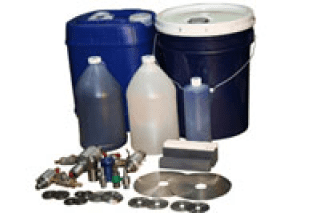
Recirculating Coolant Systems
Recirculating coolant systems are essential in dicing operations, as they ensure a continuous supply of clean coolant to the cutting zone. These systems require effective filtering mechanisms to remove swarf particles generated during the cutting process. The type of filtering process used—cartridge, centrifugal, or cascade—depends on the specific application and requirements.
Filtering Processes:
-
Cartridge filters: These filters trap swarf particles as coolant passes through replaceable cartridges. They are suitable for applications requiring fine filtration and are relatively easy to maintain.
-
Centrifugal filters: These systems use centrifugal force to separate swarf particles from the coolant. They are effective for removing larger particles and are ideal for applications with high volumes of debris.
-
Cascade filters: This method involves a series of filtration stages, progressively removing finer particles at each stage. Cascade filters are highly effective for ensuring a high level of coolant purity.
Excessive amounts of swarf particles mixed in the coolant can impede heat transfer and potentially cause surface damage to the material being cut. Therefore, the coolant system must be constantly controlled and monitored to ensure process consistency and maintain optimal cutting conditions.
Coolant Temperature: Coolant temperature significantly affects blade life and cut quality. The ideal coolant temperature is typically around 50 degrees Fahrenheit (10 degrees Celsius), providing the best results in terms of cooling efficiency and material protection.
Temperatures above 80 degrees Fahrenheit (27 degrees Celsius) should be avoided, as they can degrade coolant performance and lead to increased blade wear and inferior cut quality.
Using refrigeration in the coolant system can help maintain the optimal temperature. Refrigerated coolant systems are compatible with most types of coolant and significantly improve cooling efficiency and overall cutting performance.

Monitoring Blade Wear
Monitoring blade wear is crucial to maintaining optimal performance and ensuring the longevity of diamond dicing blades. Regular checks and early identification of wear and tear can prevent potential issues and minimize downtime.
To ensure timely intervention, it is essential to identify signs of wear and tear early. One of the first signs of blade wear is a noticeable reduction in cutting efficiency. If the blade takes longer to cut through materials or if the cuts are not as clean and precise as before, it may be due to blade wear. Unusual noise or increased vibration during the cutting process can signal blade wear or damage, as worn blades may cause the machine to operate less smoothly, leading to increased operational noise and vibration. Regular visual inspections of the blade can reveal obvious signs of wear such as cracks, chipping, or deformations.
Look for any irregularities along the cutting edge or the body of the blade. Additionally, a decline in the quality of the surface finish of the cut material can indicate blade wear. If the material surface appears rougher than usual or shows signs of irregularities, the blade may need attention. Increased heat generation during cutting can also be a sign of a worn blade, observable by monitoring the temperature of the blade and the workpiece during operation.
Implementing a routine maintenance schedule for blade inspection and upkeep is essential for optimal performance. Conduct regular inspections based on the blade's usage and the manufacturer's recommendations. These inspections should be thorough and include both visual and operational checks. Clean the blade regularly to remove debris, resin build-up, and other contaminants that can affect performance. Use appropriate cleaning agents and methods recommended by the blade manufacturer. Ensure that the lubrication and cooling systems are functioning correctly by inspecting and maintaining these systems regularly to prevent overheating and excessive wear.

Keep track of cutting parameters such as spindle speed, feed rate, and coolant flow. Consistent monitoring helps in identifying any deviations that could indicate blade wear or other issues. Depending on the blade type and material being cut, periodic sharpening may be necessary. Follow the manufacturer’s guidelines for sharpening to restore the blade’s cutting edge. Maintain detailed records of blade usage, maintenance activities, and any issues encountered to help track the blade’s performance over time and predict when maintenance or replacement is needed.
For more precise monitoring, advanced techniques can be employed. Acoustic emission sensors can detect sound waves generated by blade wear, providing real-time data on blade condition and helping in early detection of wear. Infrared cameras can be used to monitor the temperature of the blade and the workpiece during cutting, with abnormal temperature patterns indicating wear or other issues. Vibration sensors can monitor the vibration levels during cutting, as changes in vibration patterns can be indicative of blade wear or machine misalignment. Periodically examining the blade under a microscope can detect micro-level wear and damage that may not be visible to the naked eye.
Surface Speeds in Dicing
Typical surface speeds in dicing applications range from 60 to 120 meters per second (m/s). For nickel-bonded blades on silicon, a surface speed of approximately 90 m/s is recommended. When using resin-bonded dicing blades, altering the surface speed can influence blade behavior. If the chuck speed is kept constant, increasing the rotational speed will simulate the effects of using a harder bond, resulting in longer blade life but more chipping. Conversely, reducing the rotational speed will soften the cutting action, potentially reducing chipping but also shortening blade life.
Spindle Speed / RPMs
Selecting the correct spindle speed, measured in revolutions per minute (RPM), is crucial for optimizing the cutting performance of diamond dicing blades. Different materials have specific requirements for cutting speed, influenced by factors such as material hardness, density, and the inherent properties of the material being processed. Proper adjustment of spindle speed affects both the blade wear and the quality of the cut.
Understanding Material Requirements
Material properties play a significant role in determining the appropriate spindle speed. Harder materials, such as ceramics and semiconductors, generally require lower spindle speeds. These materials are brittle and prone to chipping or cracking under high-speed cutting conditions. Lower spindle speeds result in a softer dicing action where each diamond particle grinds away larger portions of the material, reducing the risk of damage and extending blade life.
In contrast, softer materials, such as certain plastics and soft metals, can be cut at higher spindle speeds. Higher speeds result in a harder dicing action, where each diamond particle removes smaller portions of the material. This approach minimizes the risk of melting or deformation in softer materials, ensuring a cleaner and more precise cut.
Effects of Low Spindle RPMs
Operating at lower spindle RPMs can have several effects on the cutting process. One of the primary impacts is increased blade wear. At lower speeds, the diamond particles on the blade remove larger chunks of material. This process, while softer in terms of cutting action, can cause the blade to wear out faster. The increased contact area and larger material removal rate put more stress on each diamond particle, leading to faster degradation of the blade.
Despite the increased wear rate, lower spindle speeds can offer benefits in terms of cut quality. The softer dicing action reduces the likelihood of chipping and cracking, especially in brittle materials. This can be particularly important for applications requiring high precision and minimal material damage, such as in the microelectronics and semiconductor industries.
When working with materials like silicon wafers or advanced ceramics, maintaining a low spindle speed helps in preserving the structural integrity of the material. The blade grinds through the material more gently, which is crucial for preventing fractures or micro-cracks that could compromise the functionality of the final product.
Effects of High Spindle RPMs
Higher spindle RPMs create a harder dicing action, with each diamond particle grinding away smaller portions of the material. This approach is generally more efficient for softer materials, where higher speeds can produce cleaner cuts with smoother edges. The reduced contact area per particle means less friction and heat buildup, which is advantageous for materials sensitive to temperature changes.
However, higher spindle speeds can also introduce challenges. Increased speeds can lead to more heat generation, which might cause thermal damage or deformation in certain materials. Moreover, higher speeds require more precise control to avoid vibrations and maintain cut accuracy. The increased centrifugal force at higher RPMs can also stress the blade, potentially leading to instability if the machine and blade are not properly calibrated.
For materials like soft metals or polymers, high spindle speeds can achieve faster processing times and finer surface finishes. The rapid rotation ensures that the blade interacts with the material frequently but briefly, reducing the risk of pulling or tearing the material.
Optimizing Spindle Speed for Different Materials
To optimize spindle speed for different materials, start by consulting the manufacturer's recommendations for both the blade and the material. These guidelines provide a baseline for appropriate spindle speeds, considering factors such as material hardness, thickness, and desired cut quality.
This table summarizes the recommended RPM and feed rate ranges for various applications based on the common materials used in each application.
|
Application |
Common Materials |
Recommended RPM |
Feed Rate (mm/s) |
|---|---|---|---|
|
BGA (Ball-Grid Array) |
FR4, epoxy mold compound |
25,000 - 30,000 |
10 - 20 |
|
QFN (Quad Flat No Lead) |
C194, epoxy mold compound |
20,000 - 25,000 |
5 - 15 |
|
LED (Light-Emitting Diode) |
Copper |
15,000 - 20,000 |
10 - 15 |
|
HTCC (High Temperature Co-fired Ceramics) |
20,000 - 25,000 |
5 - 10 |
|
|
LTCC (Low Temperature Co-fired Ceramics) |
25,000 - 30,000 |
10 - 20 |
|
|
CMOS (Complementary Metal-Oxide Semiconductor) |
Borosilicate Glass |
15,000 - 20,000 |
5 - 10 |
|
HTCC (High Temperature Co-fired Ceramics) |
20,000 - 25,000 |
5 - 10 |
|
|
DWDM (Dense Wavelength Division Multiplexing) Filters |
Glass, Quartz |
20,000 - 25,000 (Glass) |
5 - 10 (Glass) |
|
25,000 - 30,000 (Quartz) |
3 - 8 (Quartz) |
||
|
HDD (Hard Disk Drive) |
AlTic (Aluminum Titanium Carbon) |
15,000 - 20,000 |
5 - 10 |
|
Ferrite Ceramic |
20,000 - 25,000 |
3 - 8 |
|
|
Semiconductor Wafer |
|||
|
Silicon |
25,000 - 30,000 |
10 - 20 |
|
|
LiNbO3 (Lithium Niobate) |
20,000 - 25,000 |
5 - 10 |
For harder materials, begin with a lower spindle speed and gradually increase it if necessary, while monitoring the cutting performance. Look for signs of excessive wear, heat generation, and cut quality to determine the optimal speed. Ensure that the spindle speed remains within the recommended range to prevent blade damage and maintain precision.
For softer materials, higher spindle speeds may be more appropriate. Start with a moderate speed and adjust upwards, paying attention to the cut quality and any signs of thermal damage or deformation. Use real-time monitoring systems to track spindle load, temperature, and vibration, making necessary adjustments to achieve the best results.
Balancing Blade Wear and Cut Quality
Achieving the right balance between blade wear and cut quality involves continuous monitoring and adjustment. Regularly inspect the blade for signs of wear and replace it as needed to maintain cutting efficiency. Implement a feedback loop to adjust spindle speeds based on cutting performance, ensuring that the settings remain optimal for the specific material and cutting conditions.
Utilize advanced monitoring technologies, such as acoustic emission sensors and infrared thermography, to gain deeper insights into the cutting process. These tools can help detect subtle changes in blade performance and material interaction, allowing for proactive adjustments that enhance both blade life and cut quality.
Feed Rate
The feed rate in diamond dicing operations is a critical parameter that significantly influences cut quality, blade wear, and overall production efficiency. The optimal feed rate should be determined based on desired cut quality, material hardness, density, and thickness.
Determining the Optimal Feed Rate
The desired cut quality is a primary consideration when setting the feed rate. Higher feed rates can increase cutting speed and output but often at the expense of cut quality. This trade-off must be carefully managed to ensure that the final product meets the required specifications. The feed rate must be balanced to avoid excessive chipping and material cracking, which can increase die rejection rates and compromise the integrity of the cut.
Material hardness and density are also key factors in determining the feed rate. Harder and denser materials require slower feed rates to ensure that the blade can effectively cut through the material without causing damage. For example, cutting materials such as silicon wafers or advanced ceramics typically necessitates a slower feed rate to prevent chipping and ensure a smooth cut. In contrast, softer materials like certain plastics or soft metals may tolerate higher feed rates, allowing for faster cutting without compromising quality.
Material thickness also influences the appropriate feed rate. Thicker materials generally require slower feed rates to maintain control and precision during the cutting process. Thinner materials may allow for faster feed rates, but careful monitoring is still essential to prevent deformation or damage.
Balancing Production Efficiency and Cut Quality
Many high-production dicing operations face pressure to meet production quotas and reduce costs. This often leads to the temptation to increase feed rates to meet demanding production targets. While increasing feed rates can lead to short-term gains in production speed, it can also result in significant long-term drawbacks. Excessive feed rates can cause increased chipping, material cracking, and higher die rejection rates. These issues lead to additional costs and time associated with redoing the dicing operation, using extra material, and increased labor for correcting out-of-spec parts.
To maintain a balance between production efficiency and cut quality, operators should adhere to the feed rate best suited for the required cut quality. This involves careful calibration and monitoring of the feed rate during the dicing process. Advanced dicing machines often come equipped with control systems that allow for precise adjustments to the feed rate, ensuring consistency and accuracy. Implementing such systems can help operators maintain optimal feed rates without compromising on cut quality.
Monitoring and Adjusting Feed Rates
Continuous monitoring of the feed rate is essential to ensure that it remains within the optimal range for the specific material and cutting conditions. Operators should regularly check the quality of the cut and make necessary adjustments to the feed rate based on real-time observations. Using sensors and feedback systems can provide valuable data on the cutting process, helping to identify any deviations that could affect cut quality.
Implementing a feedback loop where the feed rate is continuously adjusted based on cutting performance can help in achieving consistent results. For example, if increased chipping or cracking is observed, the feed rate should be reduced to allow for more controlled cutting. Conversely, if the cut quality is satisfactory, and there is room for improving production speed, the feed rate can be gradually increased while closely monitoring the results.
Dressing Dicing Blades
Resin Bond Dicing Blades: Self-Dressing and Maintenance
Resin bond dicing blades are known for their softer binder material, which offers unique advantages in the cutting process. The soft binder allows the blade to conform to the material being cut, facilitating smoother cuts and reducing the risk of damage to delicate workpieces. This softness also contributes to the blade's self-dressing capabilities, meaning that the blade can maintain its sharpness and cutting efficiency without extensive external dressing.

One of the standout features of resin bond dicing blades is their self-dressing property. As the blade cuts through the material, the cutting action itself helps expose fresh diamond particles embedded in the resin bond. The friction and heat generated during cutting cause the resin binder to wear away gradually, continuously exposing new, sharp diamond edges. This intrinsic self-dressing characteristic makes resin bond blades ideal for applications where maintaining a sharp cutting edge is critical, yet frequent manual dressing would be impractical or inefficient.
In most cases, resin bond dicing blades require minimal dressing because they are typically dressed by the material they are cutting. However, there are scenarios where some light dressing might be necessary to ensure optimal performance. When a new resin bond blade is installed, an initial light dressing might be needed to expose the first layer of diamond particles and prepare the blade for cutting. This can be achieved by making a few cuts on a sacrificial piece of the same material or a dressing stick designed for this purpose. Over time, if the blade shows signs of glazing, indicating dulled diamonds, a light dressing can rejuvenate the blade by briefly cutting into a dressing stick or a similar material to remove any resin buildup and expose fresh diamonds. Additionally, if the cutting application changes to a significantly different material, dressing the blade might help optimize its performance for the new material, ensuring the blade’s surface is properly conditioned for the specific characteristics of the new material.
Regularly monitor the blade's performance during cutting. Indicators such as increased cutting force, reduced cut quality, or slower cutting speeds can signal the need for dressing or blade replacement. Ensure adequate coolant flow to maintain the blade temperature and prevent resin overheating, which helps minimize resin buildup on the blade surface and reduces the frequency of necessary dressing. Optimize cutting parameters, such as feed rate and spindle speed, to match the material being cut, enhancing the self-dressing action and prolonging blade life. Keep dressing sticks or suitable materials on hand for occasional light dressing to maintain the blade’s cutting efficiency without over-dressing, which can waste diamond particles.
Resin bond dicing blades are highly efficient and convenient tools for precision cutting applications, thanks to their self-dressing properties. By understanding the unique characteristics of these blades and implementing best practices for their use, operators can maximize their performance and longevity. Regular monitoring, appropriate use of coolants, and occasional light dressing when necessary will ensure that resin bond dicing blades continue to deliver high-quality cuts with minimal maintenance effort.
Dressing Nickel Bond and Metal Bond Dicing Blades
Nickel bond and metal bond dicing blades have significantly harder binders compared to resin bond blades. Due to this hardness, they require more aggressive dressing to achieve optimal performance. Dressing these blades is essential for maintaining their cutting efficiency and extending their lifespan.
Dressing Nickel Bond Dicing Blades
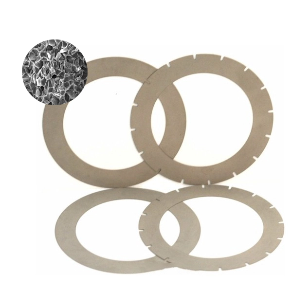
Nickel bond dicing blades, in particular, require regular dressing. The dressing process involves removing any built-up nickel or shearing off diamond particles protruding from the blade surface, which ensures that the blade remains sharp and effective.
Hubbed nickel bond dicing blades are partly pre-dressed during manufacturing, typically reducing the need for further dressing. However, non-hubbed nickel bond blades will require thorough dressing before use. The dressing process is crucial for maintaining the blade’s performance, especially when dealing with hard materials like silicon.
Nickel bond dicing blades are primarily used on silicon, and it is recommended to conduct the dressing cycle on silicon as well. This ensures that the blade is conditioned appropriately for its primary cutting application. The dressing cycle typically involves multiple steps with varying table speeds, starting slow and gradually increasing until the production speed is nearly reached. This gradual increase helps in evenly dressing the blade surface without causing damage or excessive wear.
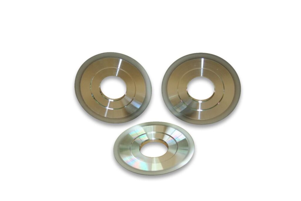
Great care must be taken to ensure that the dressing depth is deeper than the required production cutting depth. This precaution ensures that only the dressed sections of the blade are used during production cutting, maintaining consistent cutting performance and quality.
Please see more about dressing >>>
Dressing Sintered (Metal Bond) Dicing Blades

Metal bond dicing blades, similar to nickel bond blades, also have a hard binder and require aggressive dressing. The process for dressing metal bond blades is akin to that of nickel bond blades, involving the removal of built-up material and the shearing of protruding diamonds.
For both nickel and metal bond blades, the dressing process should be performed periodically to maintain the blade’s sharpness and cutting efficiency. Regular dressing helps in preventing the buildup of material on the blade surface, which can lead to reduced cutting performance and increased blade wear.
The blade is run against this material at varying speeds and depths to remove excess binder and expose fresh diamond particles. The dressing stick should be selected based on the blade type and the material being cut.
A typical dressing cycle might involve the following steps:
-
Initial Slow Speed: Start the dressing process at a slow table speed to gently begin the removal of built-up material.
-
Gradual Increase: Gradually increase the table speed to progressively remove more material and evenly dress the blade surface.
-
Final High Speed: Reach near production speed towards the end of the cycle to ensure the blade is conditioned for high-speed cutting.
-
Depth Adjustment: Ensure that the dressing depth exceeds the production cutting depth to use only dressed sections of the blade for actual cutting operations.
Continuous monitoring of the blade condition during the dressing process is essential. Operators should regularly inspect the blade for any signs of uneven wear or damage and make necessary adjustments to the dressing parameters. Proper maintenance of the dressing equipment and adherence to recommended dressing cycles will help in achieving optimal blade performance and extending the blade's lifespan.
Dressing process for diamond dicing blades presented in a table format:
|
Stage |
Number of Cuts |
Depth of Cuts |
Table Speed |
|---|---|---|---|
|
Initial Truing |
5-10 cuts |
50 microns |
50 mm/s |
|
First Dressing Cycle |
5-10 cuts |
PD + 100 microns |
10 mm/s |
|
Second Dressing Cycle |
5-10 cuts |
PD + 100 microns |
20 mm/s |
|
Third Dressing Cycle |
5-10 cuts |
PD + 100 microns |
30 mm/s |
|
Progressive Dressing |
Continue until production table speed is reached, increasing by 10 mm/s every 5-10 cuts while maintaining depth at PD + 100 microns |
Note: PD (Production Cutting Depth) refers to the depth of cut used during actual production cutting operations.
Dressing can be performed using various methods, each suitable for different types of blades and binders.
Chemical etching is used primarily for blades with nickel binders. This method involves submerging the blade in a chemical solution that selectively dissolves the nickel binder, exposing the diamond particles. This precise control over diamond exposure makes chemical etching an effective method for maintaining blade sharpness.
Chemical electrical etching combines chemical etching with an electrical current to enhance the etching process. This method provides even greater control and is ideal for high-precision cutting applications. The electrical current helps to accelerate the removal of the nickel binder, ensuring the diamonds are adequately exposed.
Grinding is a versatile method suitable for all blade types. It involves using a grinding wheel or abrasive stone to mechanically dress the blade. This process effectively removes debris and sharpens the diamond particles, restoring the blade’s cutting ability. Grinding requires skill to avoid over-grinding, which can damage the blade.
Surface lapping employs a lapping plate with abrasive slurry to polish the blade surface. This method is also suitable for all blade types and produces a smooth, clean surface by exposing fresh diamond particles. Surface lapping is time-consuming and may require multiple passes to achieve the desired results.
One-line dressing on the saw involves dressing the blade while it is mounted on the saw. This method uses a dressing stick or plate to maintain the blade's sharpness during regular cutting operations. One-line dressing minimizes downtime and allows for continuous maintenance of the blade. However, it may not be as thorough as other methods and might require periodic off-line dressing for complete blade maintenance.
Ensuring that the diamonds are well-protruded and exposed is crucial for effective cutting. Properly dressed blades reduce cutting forces, generate lower cutting temperatures, and improve cut quality. Sharp, exposed diamonds cut more efficiently, reducing the force required and the generation of heat, which protects both the blade and material from thermal damage. Properly dressed blades deliver cleaner cuts with fewer defects and a smoother finish.
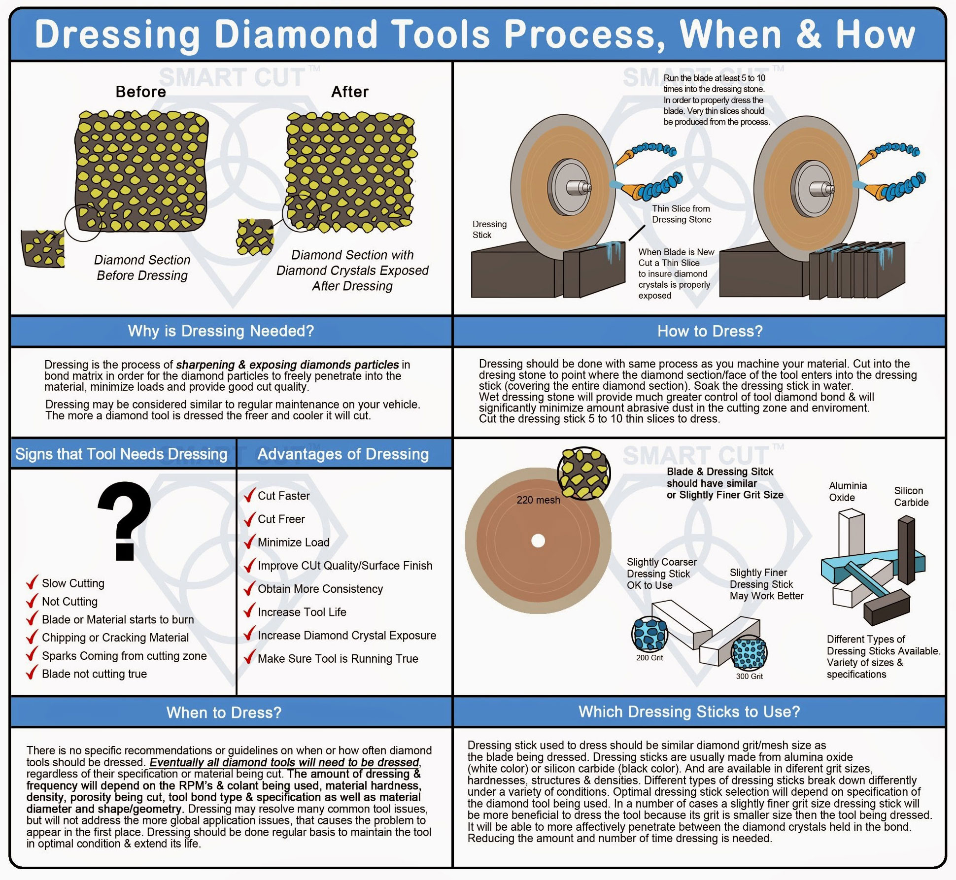
Challenges of Dicing Thick Materials: Techniques and Considerations
When dicing materials with significant thickness, several challenges need to be addressed to ensure precise cuts and optimal blade performance. These challenges include selecting the appropriate blade thickness and exposure, considering the use of multiple passes, and mitigating backside chipping.
When dicing materials with a thickness of 1/4 inch, typically a 3 or 4-inch diameter blade is required. The blade thickness must be relative to the material thickness to accommodate the spindle load generated during cutting. For materials of this thickness, a blade thickness of .020 to .030 inches is recommended. This ensures the blade is robust enough to handle the load without excessive deflection or breakage. Two primary techniques for dicing thick materials can yield different results: the single pass technique and the multiple pass technique. The single pass technique utilizes a blade with the full required exposure, making a single pass through the material. This technique is generally faster but can lead to increased blade deviation and reduced cut quality, especially at the initial stages of cutting due to the lack of support. The multiple pass technique involves gradually cutting through the material in several passes. Recommended for materials thicker than .060 inches, this method reduces the load on the blade and spindle, providing more control and precision. Drawbacks include increased processing time, as each cut must be multiplied by the number of passes. Additionally, initial passes may suffer from blade deviation due to lack of support.
For materials with a thickness of .060 inches or greater, it is recommended to use the multiple pass technique. This involves making several passes with the blade, each removing a small amount of material until the entire thickness is cut through. For example, the first pass might cut .015 inches into the material, the second pass another .015 inches, and so on until the blade reaches beyond the tape and the cut is completed. To address the drawbacks of the multiple pass technique, blade deviation during initial passes can be mitigated by using a scribe blade with limited exposure. This blade makes a preliminary cut of about .040 inches, creating trenches for subsequent cuts. After scribing, switch to a blade with the full required exposure and complete the dicing in multiple passes over the pre-made trenches. The second blade tends to follow the scribe cuts, reducing waviness and improving cut accuracy.
Backside chipping is a common issue during the final stages of cutting. It is caused by several factors, including improper cut depth, incorrect RPM or feed rate, and vibrations when the last segment of material is knocked off during the final pass. While there are no perfect solutions, the following measures can help mitigate this problem. Ensure that the cut depth is properly set to avoid excessive force on the material during the final pass. For 3 and 4-inch diameter blades, use an RPM of around 15,000. For 2-inch diameter blades, an RPM of 20,000 is recommended. Maintain a feed rate of approximately .02 inches per second, adjusting based on the material specifications and requirements. Use a sturdy tape that minimizes vibration, providing better support for the material during cutting. Select the appropriate grit size for the material being cut: for glass and quartz, use a 325 grit size; for ceramics, use a 270 grit size; for silicon, use a 3000 grit size or larger.

ARE YOU USING RIGHT DICING BLADES
FOR YOUR APPLICATION?
LET US
HELP YOU
HAVING ISSUES WITH
YOUR CURRENT DICING BLADES?
Knowledge Center

Select right Diamond Dicing Blade for your application
Dicing Blade Operations Recommendations

Optimizing Dicing Blade Performance

Trouble Shooting Dicing Problems

Application Recommendations

Dicing Blade Case Studies
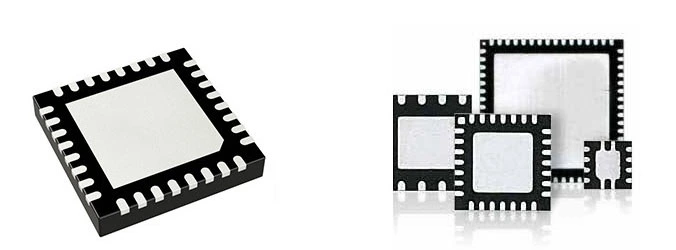
Optimizing QFN Package Dicing Process Using SMART CUT® Dicing Blades

How to Selecting Right Diamond Tools for your application

How to properly use Diamond Tools

Why use diamond

What is Diamond Mesh Size and how to select best one for your application
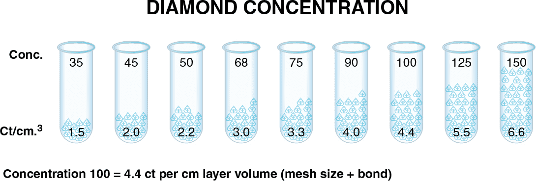
What is Diamond Concentration and which to use for your application

Diamond Tool Coolants Why, How, When & Where to Use
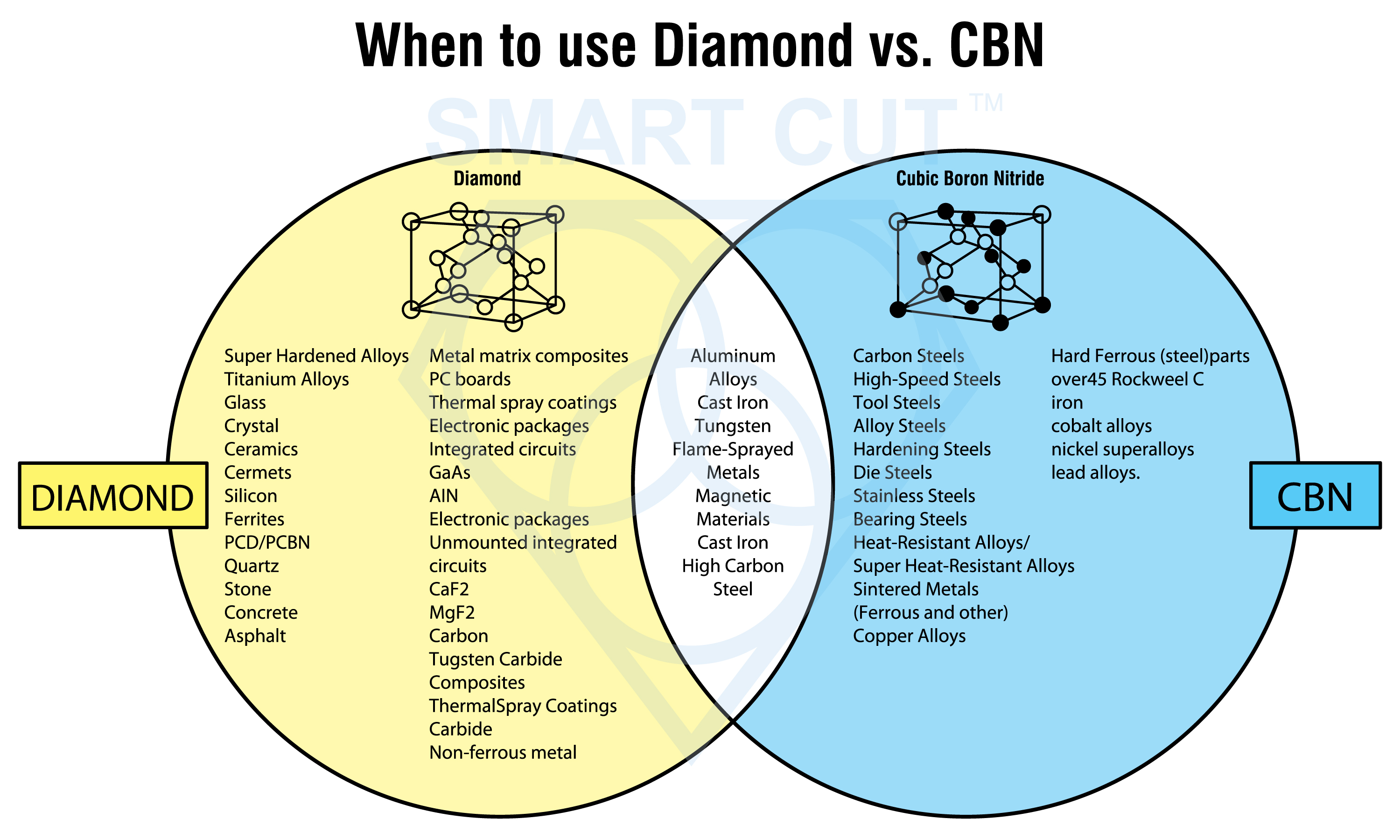
Diamond vs CBN (cubic boron nitride) Tools